
How to Choose Pad Mounted Transformer?
Table of Contents Selecting the right pad-mounted transformer requires careful consideration of several critical
ELECTRIC, WITH AN EDGE
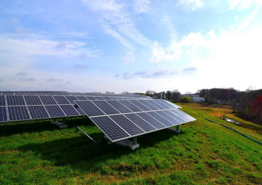
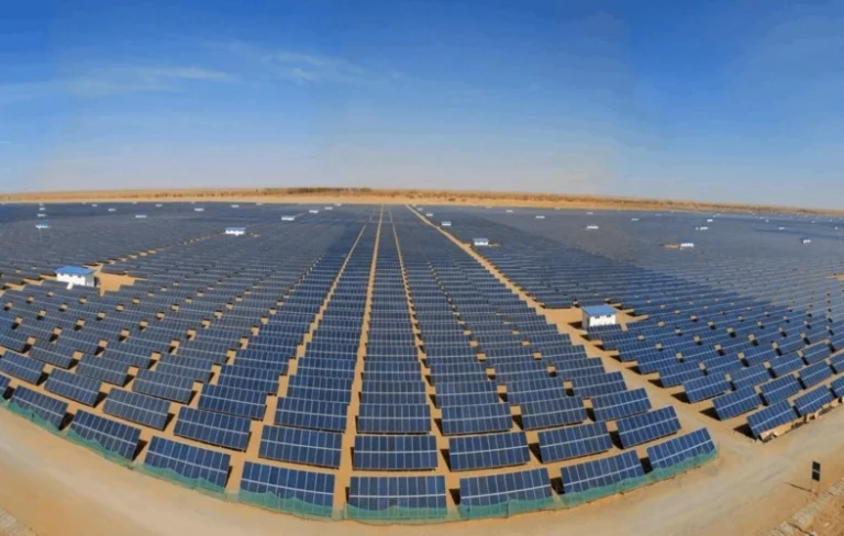
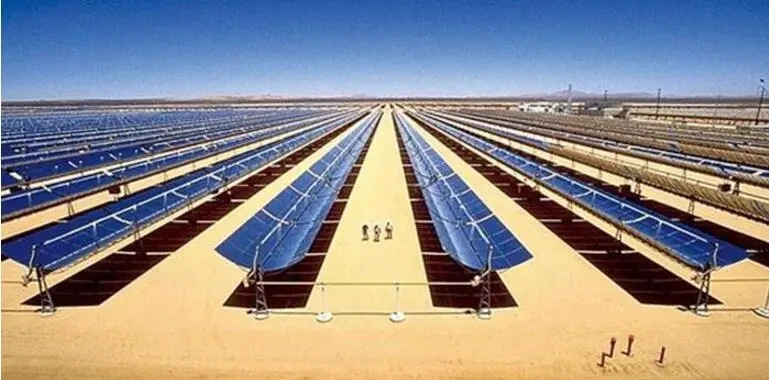
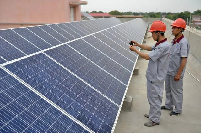
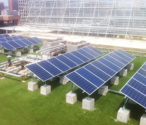
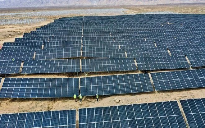
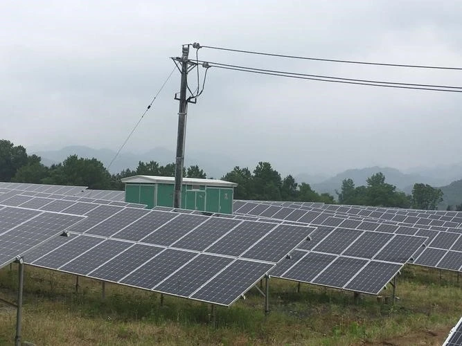
Solar energy is a renewable and clean energy source and is the cleanest, safest and most reliable energy source of the future. Photovoltaic power generation is an efficient use of solar energy. In this article, the different types of solar transformer, including step-up transformers, step-down transformers, distribution transformers, substations, pad mounted and grounding, dry-type transformers, etc., which are mainly used in solar power plants are explained in detail.
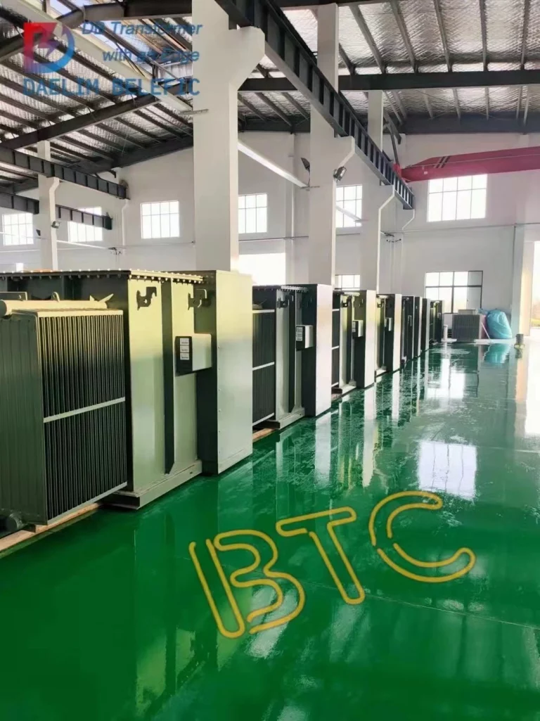
Daelim is a manufacturer of transformers with many certifications such as IEEE, ANSI, ECI, CSA, C.57, DOE and dozens of patents.
Daelim has also supplied transformer solutions to dozens of solar power plants. With this experience, Daelim offers transformers for photovoltaic power plants with large capacities, many low-voltage branches, high temperature limits, compactness, high secondary integration and ease of installation and use, which are used in a large number of applications in the photovoltaic power generation sector.
DAELIM Transformers for application in Distributed Photovoltaic (DPV) Power Generation Systems Also known as Solar Energy.
Within DPV Power Generation Systems, electricity is produced through the conversion of solar radiation into direct current (DC) electricity with semiconductors that show the photovoltaic (PV) effect.
Photovoltaic power generation is based on solar panels made up of an array of photovoltaic modules (cells) that contain the photovoltaic material. It is typically composed from silicon.
The PV module is able to produce a voltage as high as 1100V (DC).
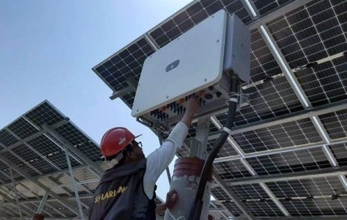
The resulting DC voltage is transformed into three-phase AC voltage by using a three-phase inverter.
The inverter then connects to an DPV the system’s inverter transformer to facilitate the distribution of the alternating current (AC) electricity.
From rooftops for residential homes to industrial and commercial applications and utility-grade power plants DAELIM’s suitable solar distribution transformers are specifically matched to various size solar inverters and their functions.
1. The dielectric fluid FR3 offers the safety of fire, reliability of equipment and a predicted lifespan far above that of a traditional mineral oil transformer, making it a crucial component of the balance of system (BOS) distributed energy resource (DER) solutions.
2. Custom-designed transformers that are optimized for specific load profiles, impedance requirements and inverter single or multiple connections
3. More overloading capability than nameplate, without the loss of insulation
4. Completely complements solar and energy balanced of system (BOS) solutions, including DC as well as AC combinationers, disconnections breakers, fuses and AC recombiners. Pad-mounted switches, reclosers mounted on poles capacitors, air switches and a complete range of services
* Based on the inverter output rating, load diagrams and the harmonics, patterns of weather, and unusual service conditions
* Designed specifically for the Inverter Transformer to work with the Pulse voltage form of Inverters
* Inverter operation isn’t dependent on the group of vectors like Dy1, Dy5 and Dy11
* There is no Neutral requirement on the primary Side of LV
* Neutral point is isolated on the secondary HV side transformer
* Recommendation to install ES between the primary and secondary windings in order to limit the possibility of transmission in high frequency disturbances (harmonics or surges, pulses, etc.)) from the primary winding to the secondary
* Windings normally connected to circuits inverters are not rounded.
DAELIM completely complies with C57.159 (2016) IEEE Guide for application in DPV Power generation Systems.
1. Experience in providing numerous projects across the American countries, including the U.S. and Canada
2. Certified with UL, cUL, CSA certificate, SGS test report, etc.
3. Complete after-sales and installation teams across Canada and the USA and elsewhere.
4. Design with the strength to maximize efficiency, special low sound levels, ambient, 50 60Hz and 60 Hz k-factor rating, etc.
5.6-7 weeks of production time
Photovoltaic power generation can be divided into two types according to how it is connected to the grid: off-grid and grid-connected. The majority of PV plants are currently grid-connected, i.e. connected in parallel to the existing power supply network to maximise the use of the electricity generated by the plant.
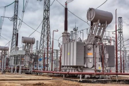
Inverters and transformers used in photovoltaic power stations are one of the important nuclear components of photovoltaic power stations. Inverters realise the conversion from DC to AC, and transformers realise the transmission and utilisation of electrical energy.
In order to reduce line transmission losses and increase transmission distances, the voltage of 270V or 400V at the outlet of the PV inverter needs to be raised and then output, i.e. a step-up transformer is installed to raise the voltage to lOkV or 3kV depending on the capacity of the power station, which reduces transmission line losses while also making the system electrically physically isolated.
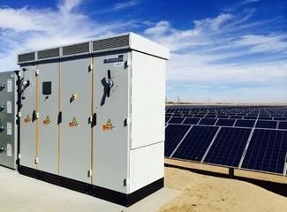
The rapid development of the photovoltaic industry has brought many opportunities for PV box-type substation manufacturers in particular.
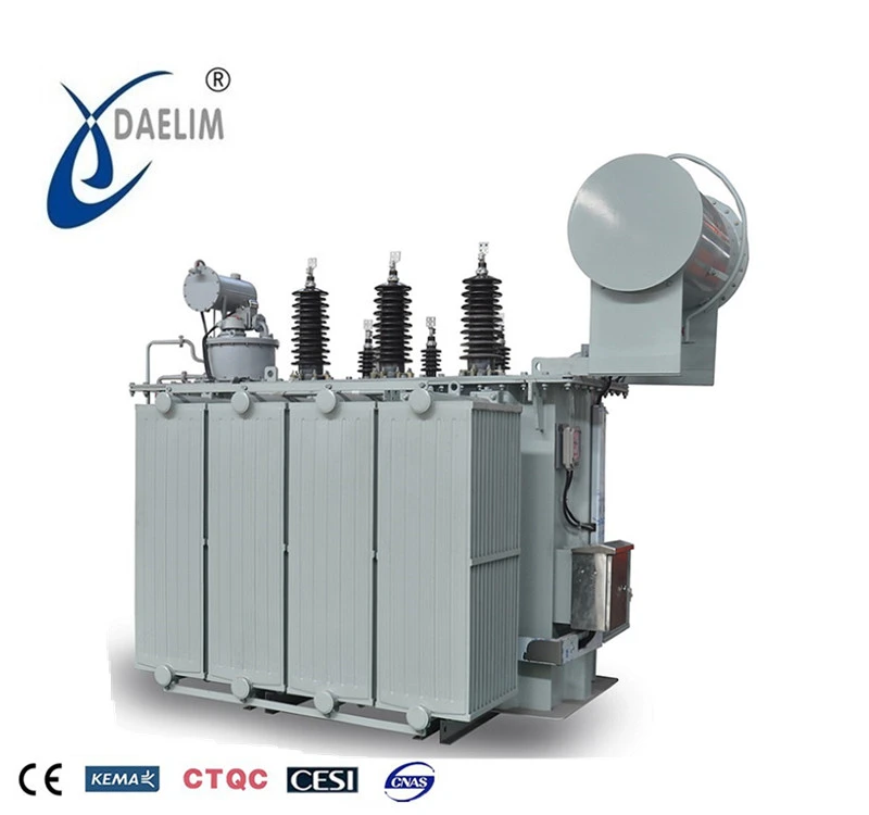
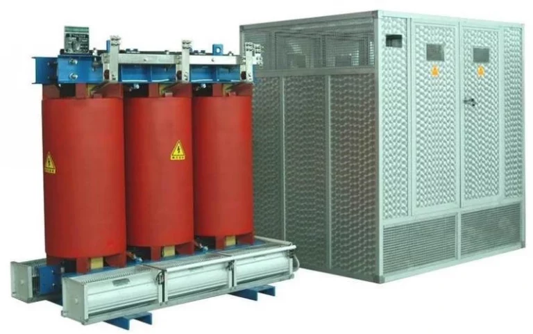
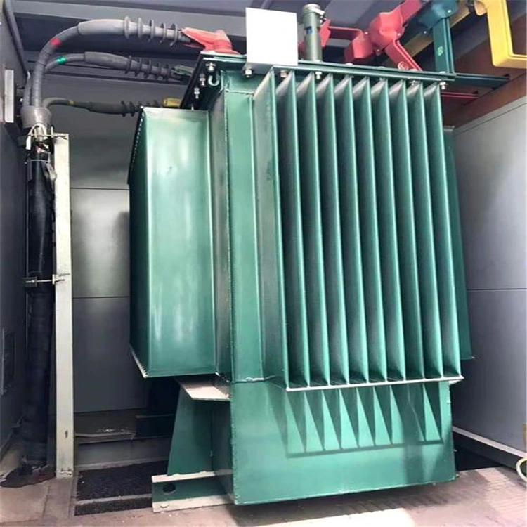
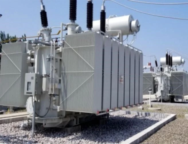
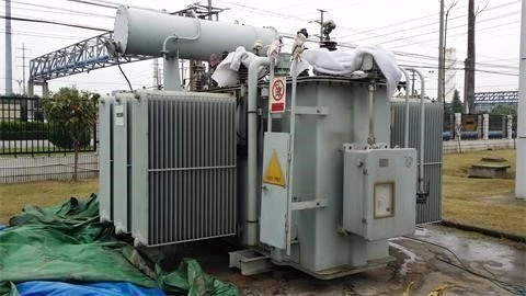
The transformer products currently used in PV substations are mainly oil-immersed transformers, which have the advantages of simple structure, strong shock resistance and high reliability.
Therefore, to vigorously develop the photovoltaic power generation business, we should start from the technical level of high and low voltage switchgear on the one hand, and improve the operation and management of the power generation network on the other hand, so as to ensure that the photovoltaic power generation system is not affected.
Photovoltaic power generation network in normal operation, must have measurement, safety protection, control, remote communication and other functions, detect the operation of the power distribution system, judge the state and make the necessary control instructions, but also all the information will be transmitted to the monitoring in a timely manner also, the degree has the basic requirements of intelligent photovoltaic pad mounted transformer.
PV pad mounted transformer as an important equipment for voltage transmission, its safety and reliability, energy saving and environmental protection, operation and maintenance and other comprehensive performance is particularly important to enhance the overall technical indicators of photovoltaic complete sets of equipment.
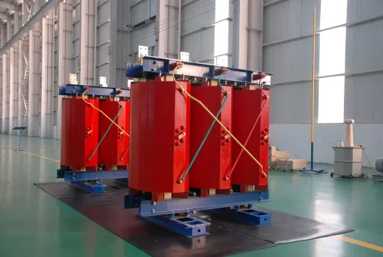
In solar power plants, two 500 k W inverters are often connected to a 1 000 kVA dry-type transformer for photovoltaic power generation in order to reduce the overall cost of the equipment and improve economy. However, in inverter systems without isolating transformers, in order to isolate the two inverters electrically from each other, a double split dry-type transformer is used.
In addition, in view of the harmonic content of the inverter system, one of the first and second windings of the dry-type transformer for solar power generation needs to be connected as a D connection.
In this way, the third harmonic can circulate in the D-connected winding, thus reducing the harmonic influence.
Therefore, this double split dry-type transformer is often designed as Dy11y11 or Yd11d11.
For 35 kV bifurcated dry-type transformers, the Yd11d11 coupling group is recommended for the following reasons.
(a) The voltage on the 35 kV side is higher, and after the coupling is Y-connected, the phase voltage of the 35 kV winding is only 1 3 of the line voltage, reducing the electric field gradient inside the high-voltage winding, reducing the possibility of partial discharge and substantially improving product reliability. For example, power transformers of 110 kV class and above are connected with Yd11 for the same purpose.
(b) low-voltage side of the current for the y connection, the phase current is equal to the line current, than d connection phase current increased by three times, need to use a larger cross-section of the conductor, which will cause the product eddy current loss increased, taking into account the impact of harmonic current, the additional loss increased even more; and when the high-voltage 35 kV side of the Y connection, due to the high voltage, rated current is small, so the conductor itself cross-section is small, eddy current loss is lower. Overall, the Yd11 connection results in lower additional losses and higher reliability.
(a) When the low-voltage side connection group is taken as d, it can provide circulation channels for the third harmonic current, improving the current waveform and power quality.
(b) When a single-phase earth short circuit occurs on the low-voltage side of the line, if the low-voltage winding is connected with d, it can provide a circulation channel for the short-circuit flow (inside the triangle) and protect the high-voltage side. If the low-voltage winding is connected by y, it cannot provide a circulation channel and will generate a great short-circuit current, endangering the high-voltage side.
(1) Temperature rise design: dry type solar transformers are usually installed in outdoor boxes or inverter room, ventilation environment is poor.
When the sun is strongest, it is the highest ambient temperature of the dry type solar transformer, and the transformer output power is also in the maximum state, so the temperature of the transformer reaches the maximum, but at night, the transformer is basically in the no-load state and the ambient temperature is low.
Therefore, the temperature of the solar power transformer is lower at this time, which can compensate for its aging life. Therefore, when designing the temperature rise of the transformer, full consideration should be given to its load and ambient temperature fluctuation characteristics, and the maximum temperature on the solar power transformer should not exceed the magnetic density of the insulation material and insulation structure.
In addition, for the double split dry-type transformer, the input side of the two groups of split low-voltage coil its upper and lower arrangement, due to the impact of air convection, the lower coil temperature rise is significantly lower than the upper coil, about 15 K lower than, so the upper coil insulation material heat-resistant grade should be slightly strengthened.
(2) Magnetic density selection: Considering the existence of voltage harmonics and DC bias magnetism, the design magnetic density of dry-type transformers for photovoltaic power generation should be more than 5% lower than that of conventional dry-type transformer products to ensure the reliability of product operation and to control product noise.
(3) Calculation of additional losses: The calculation of additional losses is based on the harmonic content of the inverter current at the output of the actual inverter and the calculated additional losses are used in the calculation of the temperature rise of the product.
For inverter systems with isolation transformers, the use of a double-winding dry type transformer means that the operating conditions are not too special.
In the case of bifurcated dry type transformers for photovoltaic power generation, however, two inverters are connected to an axial bifurcated dry type transformer.
In principle, considering that the number of solar arrays connected to each inverter is the same and that the solar panels in the same power station are subjected to the same photovoltaic irradiation at the same moment, and that the two inverters connected to the bifurcated dry-type transformer have the same valve body and control strategy The two inverters connected to the bifurcated dry-type transformer have the same valve body and control strategy.
As a result, the two voltages and currents on the input side of the bifurcated dry-type transformer are basically balanced and consistent, but in practice, due to environmental influences or inverter fault conditions, the input side of the transformer is not symmetrical up and down, or even half crossing operation occurs, and the inverter controls its output voltage strictly.
When a large deviation occurs, the AC short will remove this inverter, and when the output currents of the two inverters connected to the bifurcated dry-type transformer are unequal, the current distribution within the upper and lower split coils on the output side of the solar transformer is also unequal at this time.
As can be seen, when the output of the two inverters connected to the bifurcated dry-type transformer is not symmetrical, the internal transverse leakage field of the bifurcated dry-type transformer coil increases significantly, which will cause additional losses in the adjacent conductors and increase the temperature, which is also avoided during operation.
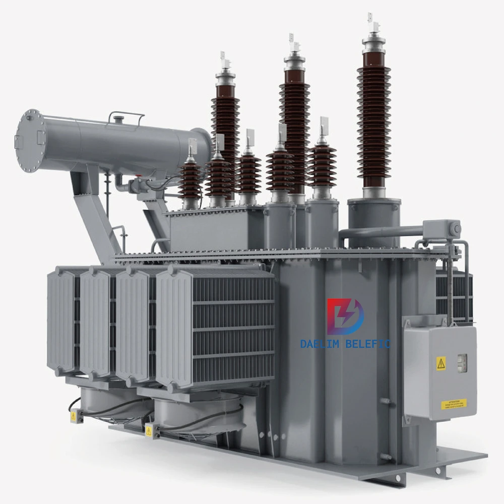
A solar step up transformer is a low loss power transformer suitable for solar power generation. As solar energy is affected by weather conditions, seasonal changes, alternating day and night and other factors, the uncertainty of sunlight intensity and duration makes the output power of photovoltaic power generation system with discontinuous and unstable characteristics, long-term low-load operation becomes the norm.
The solar step up transformer has extremely low no-load losses and is suitable for long-term low-load operation.
The solar step up transformer consists of one high-voltage winding and two low-voltage windings, and its electromagnetic working principle is similar to that of a three-winding transformer. The transformer can be split in both the amplitude and axial directions, with some differences in the manufacturing process.
The two low-voltage windings are located on either side of the high-voltage winding and have two main airways, which is more expensive to manufacture, increases the potential for insulation accidents and makes it difficult to ensure that the half crossing impedance of the two split windings is the same.
The two low-voltage windings are located on the inner side of the high-voltage winding. This splitting method, in order to ensure that the impedance of the two low-voltage windings is the same, can be staggered winding; in fact, it is equivalent to two low-voltage windings made in the form of double foil winding, but the insulation must be set between the copper foil and the copper foil, thus becoming two separate windings.
If the winding is a wire winding, it can be made into a multi-layer cylinder type, but the wire turns need to be divided into two independent leads to lead out, making it into two groups of low-voltage windings. The disadvantage is that the split impedance is small, the two low-voltage windings are magnetically coupled and affect each other more during operation.
Axial split shown: The high and low voltage windings are split axially respectively, as if symmetrical above and below. This ensures from the structure and manufacture that the parameters are basically the same, the split impedance is larger and the half crossing impedance is almost equal.
The third harmonic can circulate in the D-connected winding, which effectively reduces the impact of harmonics on the grid. For 10 kV photovoltaic step-up transformers, the Dy11y11 form is available, in line with common distribution habits.
For 35 k V photovoltaic step-up transformers, the Yd11d11 form is more recommended. The high voltage is Y-connected, the phase voltage is 1/3 of the line voltage, the winding local discharge is easy to control and the quality is more guaranteed.
When the solar inverter is in actual operation, the waveform is usually in an asymmetrical condition, which means that DC bias is generated.
When DC bias occurs, the DC component is isolated by the booster transformer and will not flow into the grid, but will cause the magnetic density of the transformer core to superimpose and increase, and the excitation current and noise will also increase, which can cause core saturation and excitation current distortion in severe cases. Therefore, it is recommended to reduce the magnetic density by 0.05 to 0.1 T compared to conventional products.
If the user has higher noise requirements, the relationship between magnetic density and noise (for every 0.05 T increase in magnetic density, the core no-load noise increases by about 2 d B, while the finished transformer can increase by about 5 d B), the appropriate reduction in magnetic density design.
Considering the influence of the inverter output current harmonics, the temperature rise design should include a cumulative calculation of winding DC losses, electromagnetic line eddy current losses and harmonic influence losses. Precise calculations facilitate cost control while ensuring that the transformer’s hottest point temperature does not exceed the permissible temperature of the insulation material.
In particular, for solar step up transformers, because of the high axial split winding, the convection of cooling air from the bottom to the top of the winding often results in a temperature difference of more than 10 K in the upper winding compared to the lower winding, which requires a lower temperature rise design or a higher thermal class of insulation material for the upper winding.
Photovoltaic power generation is often installed in places with harsh climatic conditions, and for high altitude operating areas, insulation levels and temperature rise limits have to be corrected. When the ambient temperature exceeds the normal conditions specified in the standard, the temperature rise limit should also be corrected by reducing the excess.
The low voltage winding is made of copper foil, the upper and lower split windings are arranged symmetrically, and are wound synchronously with a double-layer foil winding machine integration, with good end flatness and easy size control.
Oil-immersed transformers must have a rigid epoxy skeleton on the inside of the low voltage winding, strong enough to withstand the amplitude short-circuit electromotive force, to avoid winding deformation and core stress; the gap between the split windings is filled tightly with epoxy plates.
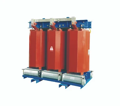
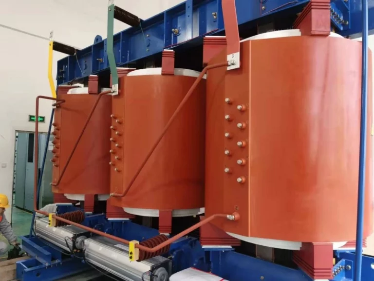
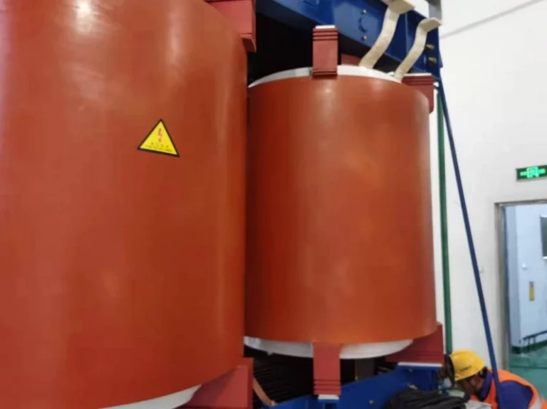
Dry-type transformers are cast in resin as a whole, and the resistance to sudden short-circuit is greatly increased.
The high voltage winding is also arranged symmetrically in the middle, with a reasonable arrangement of the wire turns to achieve a balanced safety turn as far as possible. The high and low voltage windings of the oil-immersed transformer are sleeved and the whole is lacquered to further improve the mechanical properties. Dry-type transformers have two sets of split windings cast in resin to form a single unit.
Transformers are critical components in solar energy production and distribution. Historically, transformers have “stepped-up” or “stepped-down” energy from non-renewable sources. Historically, transformers have “stepped-up” or “stepped-down” energy from non-renewable sources. There are different types of solar transformers including distribution, station, sub-station, pad mounted and grounding.
The output of a PV cell is DC and must be inverted to AC by an inverter before it can be connected to the grid in parallel via a step-up transformer.
However, when the inverter converts the DC output of the PV panels into AC, it introduces DC and harmonic components into the system, which not only reduces the power quality, but also increases the vibration and noise of the transformer, especially in the case of amorphous alloy transformers.
In addition, the DC and harmonic components also cause an increase in transformer no-load losses. Amorphous alloy transformers are being promoted because their no-load losses are only 1/5 of those of commonly used silicon steel transformers, and therefore the number of amorphous alloy transformers in photovoltaic power generation systems is increasing day by day.
A solar power system is a power generation system that uses the photovoltaic effect of solar cells to convert solar radiation directly into electrical energy. Photovoltaic power systems can be
Small solar power systems – the installed capacity is less than or equal to 1 MWp, and the voltage level of the power generation bus is suitable for 0.4 to 10 k V.
Medium-sized solar power systems – with an installed capacity greater than 1 MWp and less than or equal to 30 MWp, the generation bus voltage is suitable for a voltage level of 10 to 35 k V.
Large solar power systems – with an installed capacity of more than 30 MWp, the voltage level of the power generation bus is suitable for 35 k V. A photovoltaic power station is a power station where the photovoltaic power generation system is the main focus.
The solar substation design, which must be based on the DC voltage requirements at the input of the inverter, consists of a certain number of photovoltaic modules in a string, which are brought together in multiple strings through a DC sink box, inverted by the inverter and boosted by a step-up transformer into a power supply that meets the frequency and voltage requirements of the grid.
The PV power station is a combination of several PV power units (unit power modules).
The PV power generation unit is generally based on an inverter booster system, the scale and capacity of which is determined by the power station and the inverter capacity.
When an in-situ step-up transformer is connected to two inverters without isolation transformers, according to the current general level of inverter production, a double split winding transformer is generally used in order to limit the circulating current on the AC low voltage output side of the two inverters connected in parallel.
The selection of the in-situ step-up transformer is also explained: self-cooling, low-loss power transformers are preferred; the transformer capacity can be selected in accordance with the maximum output power of the PV array unit module.
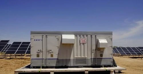
High-voltage (low-voltage) pre-assembled box-type substations or assembled substations consisting of transformers, high-voltage and low-voltage electrical equipment can be used; for PV power stations in coastal or sandy areas, when outdoor arrangements are used, the coastal protection level should reach IP65 and the sandy PV power stations should reach IP54.
It is advisable to use non-excited voltage regulating transformers; double-winding transformers or split transformers can be used.
As a new type of power generation that is environmentally friendly and can effectively improve living standards, photovoltaic power generation is gradually becoming an important part of the power system and photovoltaic power generation technology is being used worldwide.
According to authoritative statistics, grid-connected photovoltaic systems account for 40% of the current sales of photovoltaic power generation equipment and have become a trend in the field of photovoltaic power generation.
Photovoltaic power generation systems are also commonly classified into off-grid photovoltaic power generation systems and grid-connected photovoltaic power generation systems according to their relationship with the power system.
As PV power generation is characterised by daytime power generation, and the load is all-weather, off-grid PV power generation systems require energy storage equipment such as batteries.
Grid-connected photovoltaic power generation systems can then W save energy storage equipment and reduce the energy loss during battery discharge. This reduces system operating costs and improves the stability of system operation and power supply.
Large-scale grid-connected photovoltaic power generation systems place “grid-friendly” requirements on inverters, which require rapid control of frequency, voltage, current, phase, active and reactive power, power quality (voltage fluctuations, high harmonics), etc., and expand communication functions.
The integration of large scale renewable energy generation into the grid is an important feature of smart grids, so large scale PV grid integration must have grid-source interaction technology that meets the standards of smart grids.
The integration of large-scale photovoltaic power generation will cause a series of problems such as voltage fluctuations in the grid, line transmission power exceeding the limit, system short-circuit capacity increasing and system transient stability changing, which seriously restrict the ability of the grid to accept photovoltaic power generation.
Therefore, a lot of research has been done on the new PV power generation and grid-connected control technology and the impact of PV power generation on the system.
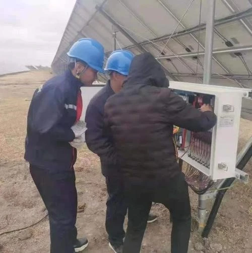
The intelligent monitoring system of PV power station refers to the intelligent monitoring and management system that uses advanced sensors, controllers, communication equipment and other intelligent equipment to achieve the functions of data collection, fault monitoring, data storage and remote monitoring of PV power station operation.
Most of the existing PV power plant intelligent monitoring systems are only real-time detection of the operating status of various adjustable equipment in PV power plants, and when the equipment fails, alarm signals are issued to notify maintenance personnel, and do not have the function of inverter group optimization control.
In addition, the current market of photovoltaic power plants using a wide range of equipment, poor compatibility, it is difficult to constitute a unified monitoring system.
To sum up, a PV plant intelligent monitoring system that can be compatible with various devices, carry out optimal and coordinated control of multiple inverters and achieve complete and unified real-time monitoring of the PV plant will be the trend in the development of PV plant monitoring systems.
In addition, as large photovoltaic power plants are generally built in remote areas, the data signal through the communication bus for long-distance transmission attenuation serious, not suitable for the use of wired monitoring system.
Therefore, the development prospects of remote monitoring systems based on wireless communication technologies such as GPRS and CDMA are also very broad.
Due to the limitation of inverter capacity, solar substation generally connects PV modules and inverters into a minimum power generation unit, and uses double split step-up transformers to form a power generation unit module, i.e. one step-up transformer is connected in parallel with two sets of inverter minimum power generation units. This effectively reduces the number of transformers and limits the circulating current on the AC output side of the two inverters connected in parallel.
The output voltage of the inverters is mainly 270, 315 and 400 V. The solar step-up transformer is used to step up the voltage to 10 kV or 35 kV in situ and is finally fed into the transmission and distribution system to complete the grid connection.
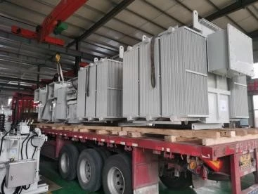
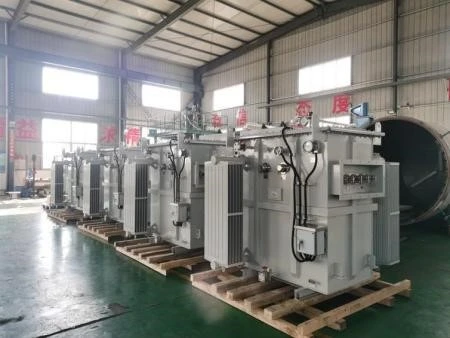
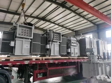
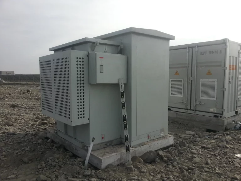
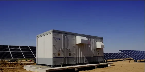
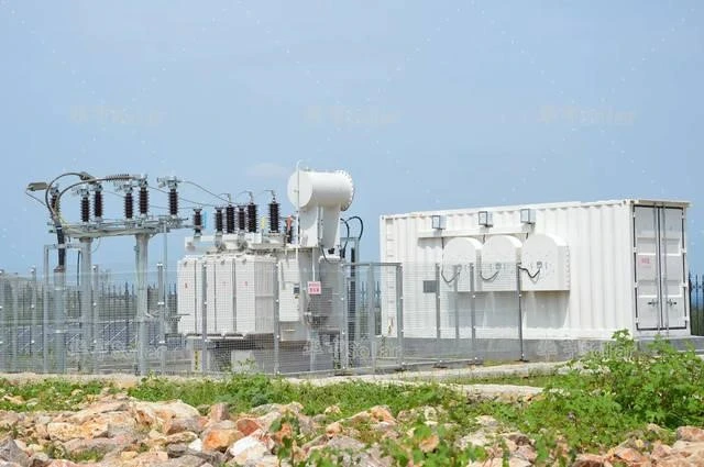
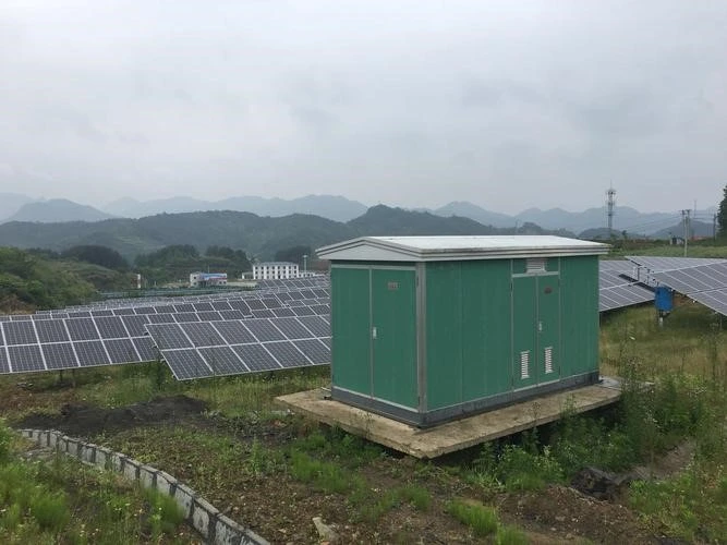
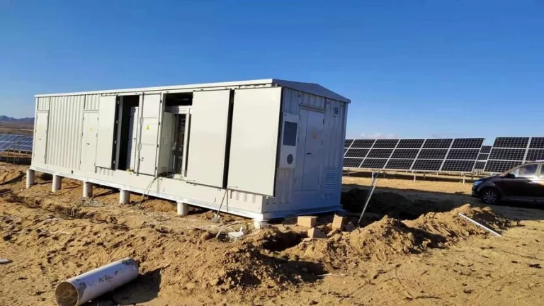
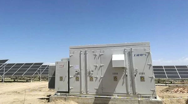
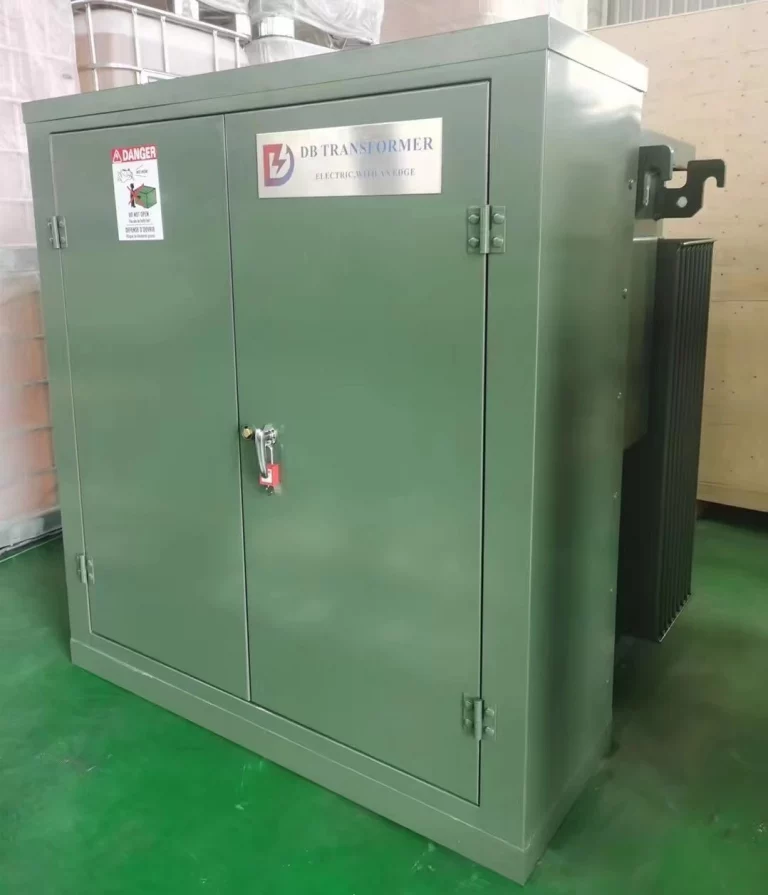
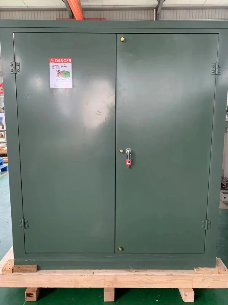
The solar step-up transformers are generally supplied as combined transformers (pad-mounted transformers) or pre-assembled substations (European transformers) as complete units.
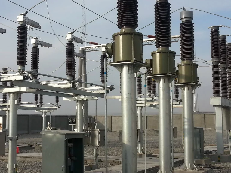
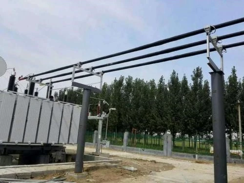
Faults in the operation of a booster station are mainly classified as transmission line faults, busbar faults, transformer faults, high-voltage switchgear and ancillary equipment faults, relay protection device faults, etc.
The most common causes of faults in the operation of the PV area are faults caused by irregularities in the construction and installation process, faults caused by the failure to install and commission the inverter, faults caused by the failure to install and commission the inverter and faults caused by the failure to inspect the subsidiary equipment of the booster transformer and faults caused by the failure to detect hidden problems in time.
Communication and automation faults may not affect the power generation operation of the equipment for the time being, but they may adversely affect the operational analysis and detection of equipment defects and their elimination, as well as prevent the equipment from being operated remotely, leaving a hidden danger for safety production, which will lead to the expansion of accidents if not taken seriously.
The main causes of failure are: soft ground causing subsidence, resulting in deformation of the equipment and making it difficult to operate, insufficient safety distances causing electrical grounding and short circuits. Corrosion of electrical equipment by salt spray, as well as evaporation of water vapour causing equipment blocking off, insulation decline, short circuit faults caused by small animals entering electrical equipment, etc.
In theory, all kinds of accidents and large faults should be able to eliminate the occurrence of, but the actual operation of power safety accidents occur from time to time, all kinds of equipment failure or defects are very common.
In theory, all kinds of accidents and major faults should be able to be eliminated, but in actual operation, power safety production accidents occur from time to time, and all kinds of equipment faults or defects are very common.
(1) At the beginning of the design, especially in the early stages of PV, there are inherent defects. Due to the simple and intuitive nature of the PV power generation process, the construction of PV power generation was a flurry of activity, with no sound experience to draw on.
(2) Because of the need to rush the construction schedule, the technical management of the construction team could not be strictly controlled, resulting in construction techniques and specifications failing to meet the requirements, leaving hidden dangers for later operation.
(3) There is no mature operational inspection, and the quality of the equipment supply units cannot be identified. This results in poor reliability and high failure rate of the equipment during operation.
(4) The quality of personnel can not keep up with the requirements of development, photovoltaic operation and maintenance personnel, most of them are new employees, completely in the state of learning by doing, some enterprises are by one or two old employees of thermal power, through the old to lead the new way to train new staff running analysis ability, the ability to find abnormalities, the ability to eliminate defects and the lack of ability to deal with accidents.
(1) To start at the source, at the beginning of the design, to make a design plan that meets the actual characteristics of the site, perfect and detailed, and scientifically optimised.
(2) To strengthen the whole process of infrastructure management, strict qualification review, pay close attention to process quality and specifications.
(3) Strictly control the access of equipment, and reject equipment of unqualified quality.
(4) Strengthen personnel responsibility education and technical ability training. With these 4 points, the chances of common faults can be effectively reduced.
Boost station faults belong to the range of general electrical faults, and the principles and main methods of handling them are the same regardless of the type of power generation. In particular, busbar loss and line tripping, for single busbar and single return booster stations, means a site-wide blackout. For PV, all inverter islanding protection should be activated and the inverters shut down. What the operational duty officer needs to do is to
(1) Ensure plant power, check the input of standby power and ensure the normal operation of the DC and communication systems.
(2) Check the protection action, identify the type of protection action and analyse possible fault conditions.
(3) Check the primary system, identify fault points, cooperate with dispatch, make safety measures to eliminate defects and resume operation as soon as possible.

The common faults in the operation of the PV zone are triggered by the following aspects.
(1) During the infrastructure process, the wiring of the panel installation is not firm, even some joints are not used for special connectors, the screws in the convergence box are not tightened, the blocking is not complete or the quality is too poor, etc.
(2) Equipment installation and commissioning is not serious, not in place, especially the inverter, booster change, installation, wiring, commissioning is different personnel, mutual cooperation, if there is no unified coordination, all walks of life, operation of various failures will be frequent.
(3) The characteristics of the geographical environment, caused by the failure, for example, the coastal mudflats salt spray environment, very easy to cause corrosion of equipment, cable and insulator fouling flash, causing insulation decline, equipment short circuit.
(4) Long-term operation caused by failure, mainly in the operation of equipment rotating parts, vibration, etc. caused by loose equipment, loose terminals, etc., in the PV is generally solar inverter transformer, inverter cooling fan failure, box change network door closure limit loose, convergence box fastening screws loose, loose terminal row, etc.
Whether it is a booster station or PV area equipment failure, in the PV operation are electrical equipment failure. For the prevention of electrical equipment faults and accidents.
(1) to implement the requirements of infrastructure for production services, in the construction process to ensure quality, leaving no hidden problems delivered to production.
(2) In operation, actively implement the requirements of technical supervision, according to the characteristics of the site, ahead of time to prevent.
(3) Strengthen the education of staff responsibility and the cultivation of the ability to analyze problems.
After the PV field operation equipment is adjusted and run normally, the most imperceptible faults, generally occurring in the panel to the sink box. And this kind of often at first also no obvious fault phenomenon appears, but the power in the continuous loss. The easiest and most effective way is to use a clamp-on ammeter to measure the operating current of each string to find the faulty string and further check whether it is a fuse problem or a battery board fault, or a broken string connection line, etc., and deal with it in time.
Common faults in the busbar, mainly blocking off, communication module failure and terminals, screws loose caused by ground heating or even fire.
The main method of dealing with the site, is to inspect, generally in the “spring inspection” work on the blocking repair, each bus terminal screws tighten again, basically to ensure a summer, the heating situation has been effectively improved.
Inverter failure, generally direct performance is to stop operation, or can not be self-start. Most of them occur at the early stage of operation. After a break-in period, most of these phenomena are caused by heat dissipation faults and over-temperature, but some are caused by damaged accessories or software faults. The main prevention and treatment of inverter faults lies in the daily cleaning of the filter to maintain the heat dissipation, as well as strengthening the inspection of the cooling fan and repairing and replacing it in time when abnormalities are found.
The technology of the solar power transformer is very mature, especially the dry transformer solar, under normal circumstances, the failure rate is extremely low. Common failure types are poor blocking, leading to small animal entry, cooling fan failure and loose body safety net door closures. However, in coastal areas and in fishery and photovoltaic complementary projects, the booster transformer high voltage switch cable head, cable and lightning arrester are key inspection items and are prone to faults which, if they occur, will result in the entire collector line being inoperative. The prevention and treatment of faults in the booster transformer still lies in the daily inspection in place and the timely implementation of technical supervision to prevent problems before they occur.
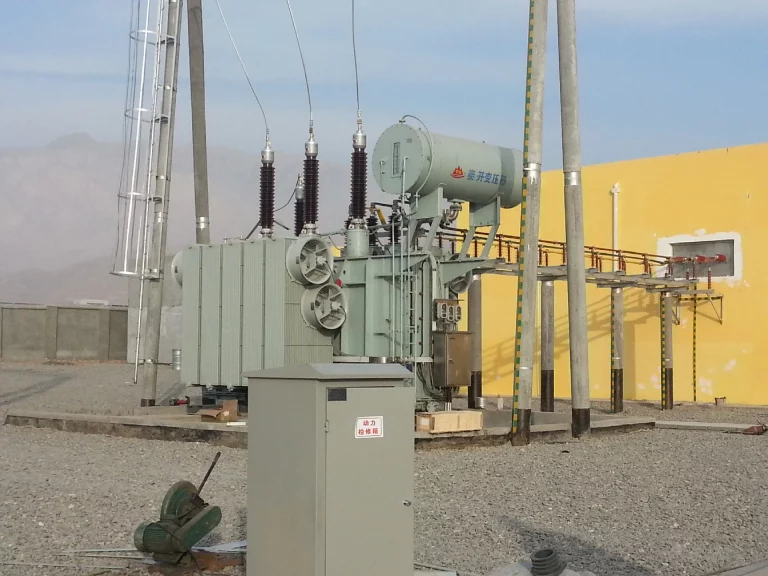
In-situ step-up transformers for large solar power plants can take the form of 35 kV combined transformers.
When the transformer body adopts an axial double split winding structure and the main components are selected to meet the output function of the telematics or remote control information quantity, the requirements of photovoltaic power generation can be well met.
When carrying out the design of the transformer, attention should be paid to the characteristics of the axial double split structure in the design of the core, coil structure and low voltage leads, as well as to the thermal insulation and heat dissipation design in the design of the housing and low voltage cabinet.
The combination of a combined transformer and a split transformer results in a 35 kV combined transformer for photovoltaic power generation, which is used as an in-situ step-up transformer in photovoltaic power stations to meet the needs of new energy development.
Maximum temperature of 41.4 °C.
Minimum temperature of -37.1 °C.
a maximum annual average temperature of 3.4 °C
maximum wind speed of 27.7 m/s.
Relative humidity (annual cumulative) of 4 9%.
annual sunshine radiation of 1665.55 kWh/m2.
Ice cover thickness of 15 mm.
Fouling class III.
Altitude ≤ 1 000 m.
Installation site outdoors.
Rated capacity of 1 000 kVA (500 kVA/500 kVA).
Rated voltage of 36.75±2×2.5%/0.4 k V/0.4 k V.
Rated frequency of 50 Hz.
Coupling group marked Yd11d11.
Crossing impedance of 6.5 %.
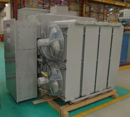
Cooling method is ONAN.
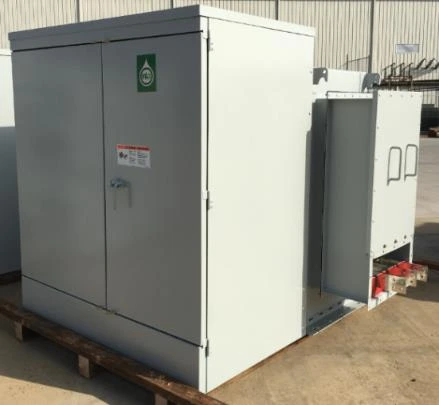
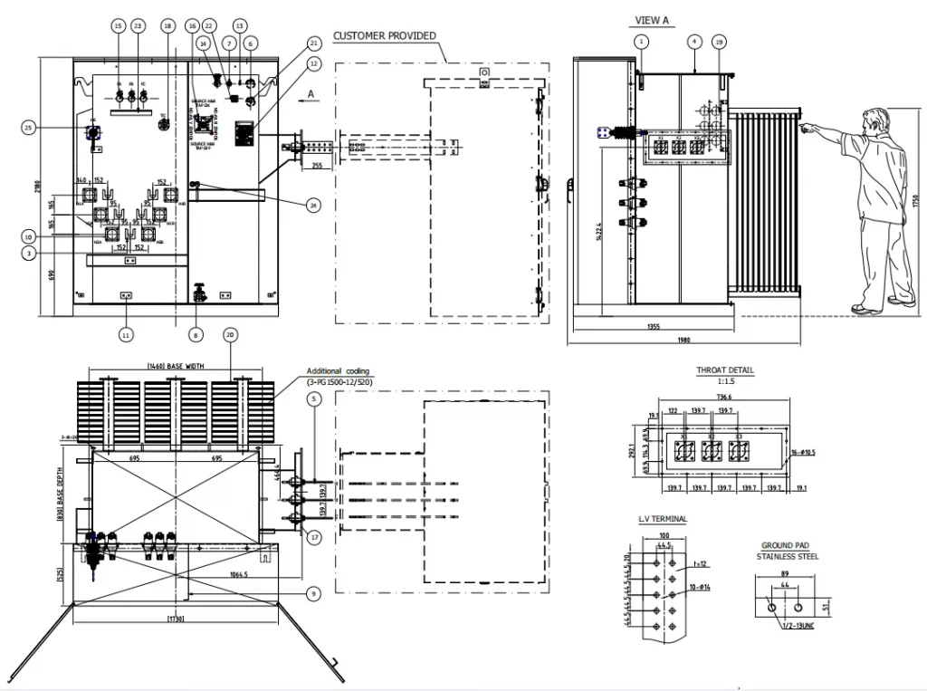
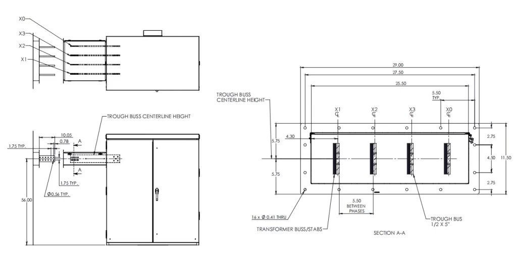
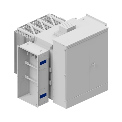
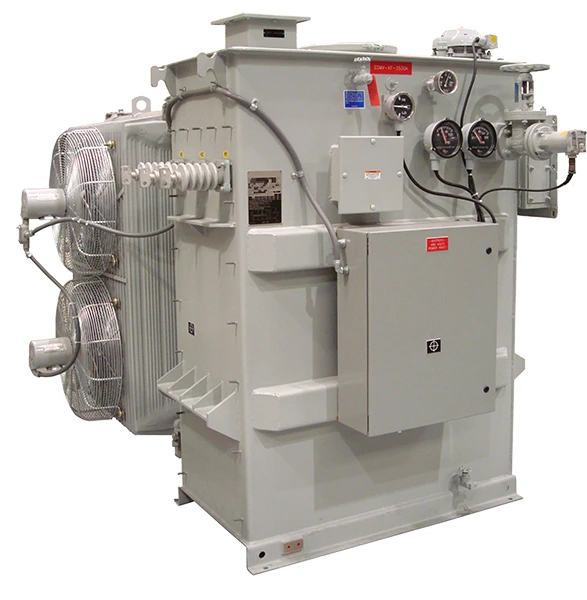
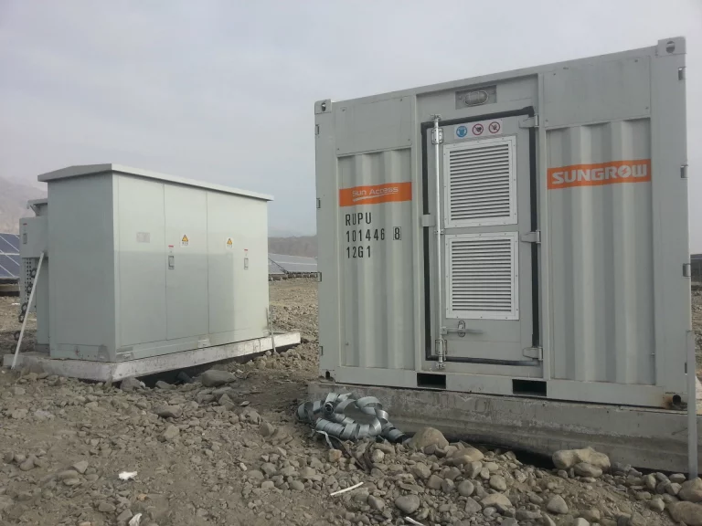
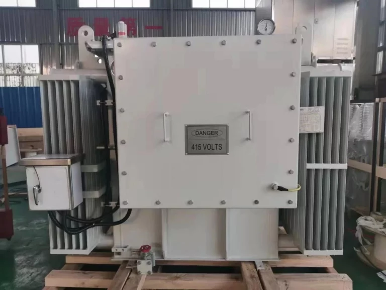
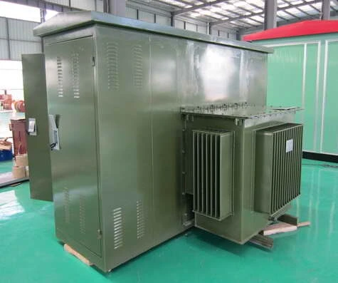
In view of the outdoor operation of the in situ solar transformer and the high level of sand and wind at the installation site, an “L” shaped 35 kV combined transformer was selected in conjunction with its technical parameters and system diagram.
A pair of long and short sides of the transformer body tank are exposed to the air as an overall heat sink, while the other pair of long and short sides extend at both ends to form an “L” shaped cabinet.
One side of the “L” type is a closed high-voltage cable room, mainly for the installation of 35 kV high-voltage cables, electrical protection, etc., independent and safe.
The other side of the “L” shape is a side-by-side high-voltage operation room and low-voltage room. The high-voltage operation room can be operated by load switches and fuses and has monitoring instruments for temperature, liquid level and pressure.
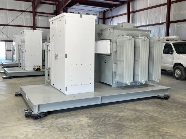
Due to the large capacity of the product and the many low-voltage output branches, and the fact that it has to be transported in a container, the external dimensions of the product are limited by the size of the container, especially in terms of height, which places high demands on the design of the solar inverter transformer.
In order to minimise the height, a four-part structure consisting of a double body was adopted.
The two bodies share a common oil tank, with each body having two parallel high-voltage circuits and a double low-voltage split. 2 bodies are connected in parallel to achieve a single quadruple split, with a total of four low-voltage outputs.
This structure reduces the height of the body on the one hand, and simplifies the structure of each body on the other hand, increasing the reliability of the product.
As the project is a high temperature insulation system, the temperature rise limit is higher than that of conventional Class A insulation products, reaching 85 K for the windings and 90 K for the oil surface. the insulation material is also different from conventional products and should be selected with a higher thermal class.
solar panel transformer design, according to the IEEE C57.154 standard, combined with the actual operating conditions of the photovoltaic box transformer, the heat generation and temperature rise of each part of the transformer to calculate, according to the different temperature rise calculation results to determine the insulation material of each location, rather than just increase the level of insulation material. This meets the requirements of transformer life and also reduces costs to the greatest extent possible.
Double body construction, each body is tensioned by means of a pulling screw. The coils are arranged from the core outwards in the sequence core – low voltage coil – high voltage coil, with phase separators placed between phases and yoke separators placed at the coil ends.
Insulating cardboard is placed between the 2 bodies.
Different high temperature resistant solid insulating materials are used in different parts of the winding, and high temperature resistant naturally degradable natural ester insulating fluid is used as the liquid insulating and cooling medium, thus building a high temperature resistant insulation system for transformers.
In response to the shortcomings of the natural ester insulating fluid’s high viscosity of movement, the size of the heat dissipation oil gap was optimised in the design process and the traditional temperature rise calculation formula was amended to make it more suitable for natural ester insulating oil products.
The low-voltage coils are double-layered, with thick flat wires arranged in multiple axial directions, eliminating the spokes arrangement and eliminating the need to transpose the middle of the coil during winding, preventing the coil spokes from being overspread and making the coil winding tighter.
The tap wire of the upper and lower part of each device is led from the middle of the device, which facilitates the connection of the leads and reduces the insulation wrapping of the tap head of the coil, improving the production efficiency and making the alignment more beautiful.
The tank adopts a barrel-type conformal structure, as shown in Figure 1. Fixed piece scattered, the box is equipped with hanging climb, fill air, oil filling pipe joints, oil discharge valve and take oil sample valve.
With connection holes to the transformer high and low voltage chambers to reduce the amount of natural ester insulating oil used. Transformer top filled with nitrogen, bottom connected to the base of the housing, with high and low voltage chambers.
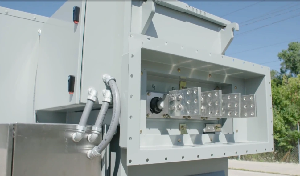
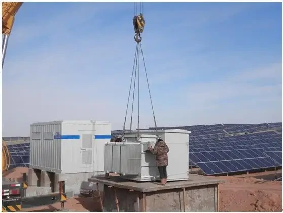
High and low voltage bushings are drawn out horizontally, the high voltage bushings are plug-in bushings and the low voltage bushings are porcelain bushings without oil conservator. The lifting climb for lifting the entire transformer is arranged on the short axis side of the transformer, the lifting point is higher than the solar inverter transformer body box cover, which facilitates lifting the entire combined transformer.
The fuse is an essential component of the combined transformer and is mainly used for protection against short circuits and overloads on the secondary side of the transformer. Due to the large capacity of the product, the existing individual back-up fuses and plug-in fuses are no longer able to match the capacity and parameters.
In the design, the high-voltage winding is split into 2 parts of 50% rated capacity each, connected as D connection, and then series into the backup fuse + plug-in fuse, after which the two high-voltage windings are then connected in parallel to form one way through the load switch, breaking through the limitation that a single fuse (plug-in + backup) cannot meet the transformer protection selection, and innovating a 35 kV voltage level large-capacity combined transformer protection for photovoltaic power generation. The technical solution.
As the neutral point is not designed in the structural design of the solar power plant pad-mounted transformer, a single-phase earth fault on the low-voltage side of the transformer can cause considerable damage to the insulation. The operating conditions of the central inverters vary, as do the fault conditions.
In the first instance, when the power generation unit is no longer operating in the absence of light, the central inverter will be disconnected from the grid, so that the inverter in standby mode will no longer act as a power generation load, but will absorb power from the grid with the aid of a pad mounted transfromer.
If a single-phase grounding occurs in the low-voltage position of the pad-mounted transformer, the line voltage received by the inverter will not change and the inverter will still work normally, but the phase voltage will increase, which will cause damage to the insulation on the low-voltage side of the pad-mounted transformer during long-term operation. However, the phase voltage will rise and, under prolonged operation, the insulation on the low-voltage side of the pad mounted transformer will be damaged, even to the point of multi-point earthing.
Secondly, if there is light, the centralised inverter will be transformed into a grid-connected state. By analysing its wiring, the pad-mounted transformer operates without grounding, and in a one-way grounded state, it is difficult to form an effective circuit with the earth, i.e. there will be no grounding current, and the line voltage of the inverter output will not change. monitoring is still the line voltage, no grounding abnormality will be detected, the inverter will still work normally, but the overall efficiency of the inverter will be reduced by the grounding influence, which in turn affects the solar power generation benefit.
Depending on the location of the disconnection, pad mounted transfromer disconnection faults are divided into high voltage lead and winding disconnection. When a disconnection occurs on the high voltage side of the pad-mounted transformer, it directly causes the inverter to trip and the generator set to shut down due to the fault.
The pad-mounted transformer is tested and found to have a sound and a special smell inside the pad mounted transformer, the winding of the faulty phase has an infinite resistance, and the DC resistance is measured and found to be infinite between the normal phase and the faulty phase winding, which basically determines the occurrence of the disconnection fault.
When a high-voltage winding disconnection fault occurs, the fault symbol will be different, mainly in that the DC resistance will not be infinite, but only twice the normal DC resistance between the two phases.
By measuring the voltage after the fault, it can be found that on the high voltage side, the line voltage between the faulted phase and the adjacent phase will be reduced, usually to 50% of the rated line voltage, while the line voltage of the normal phase does not change.
On the low voltage side, the line voltage of a phase on the low voltage side corresponding to the broken phase is significantly reduced, but does not become zero, which is mainly caused by the induced voltage.
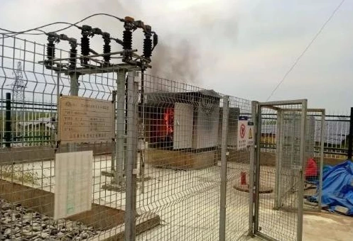
When a phase short circuit occurs on the high/low voltage side, it will cause the corresponding side of the pad mounted transfromer to trip the circuit breaker. In addition, during fault shocks, the pad mounted transfromer is often accompanied by internal noise, oil spray, odour etc.
Generally speaking, the analysis of a short-circuit fault in a pad-mounted transformer starts with the protection action and a general understanding of the pad-mounted transformer fault situation, then the pad-mounted transformer has to be transferred to the state of overhaul, with good safety measures, and the solar power unit has to be The solar power unit has to be unlisted and the fault condition viewed in detail.
If the fault develops further, the transformer can be damaged by internal winding burnout or core breakdown, and in this case the pad mounted transformer can only be scrapped.
Here the development of an actual fault in the pad-mounted transformer is analysed. Initially the fault occurs in the low-voltage side of the phase-to-phase short-circuit, which causes a breakdown short-circuit between the high- and low-voltage windings under the action of the short-circuit impact discharge. The oil inside the transformer tank is subject to serious eruptions and decomposition and deterioration. It has been found that the direct cause of short circuits between high and low voltage windings is the weakness of the insulation itself.
For the pad mounted transfromer selected in this paper, which is a three-phase, three-wire star wiring, if a single-phase grounding occurs, there will be no significant change in line voltage due to the absence of a neutral point, which increases the difficulty of grounding fault detection and the continued work of the grounded inverter may cause the grounding fault to worsen and even bring greater risks.
For this reason, the use of insulation monitoring devices can add an additional safeguard to the grid connection of the inverter unit, and in the event of an earth fault, an insulation fault alarm will be issued directly, and the faulty unit will be unlisted.
In addition, to better cope with solar pad mounted transfromer earth faults, inverters with neutral wiring should be used, and their wiring group should be of the yn11 type.
In order to ensure the operational safety of solar power plants, regular monitoring work should be carried out in strict compliance with the regulations, especially in the area of insulation monitoring, to enable more timely detection of insulation defects in the pad mounted transfromer and reduce the chance of equipment failure in the station. In the actual operation and maintenance of solar power stations, the frequency of insulation monitoring of pad-mounted transformers needs to be increased appropriately.
The analysis of pad-mounted transformer faults in solar power stations shows that defects in the internal insulation are the key cause of high-voltage faults, and in order to avoid similar faults, the internal oil samples of the pad-mounted transformer need to be tested.
From defects in the internal insulation to faults, which accumulate over a long period of time, there are usually exothermic or discharge problems during the deterioration process, which in turn cause the oil sample to become a bye word.
Regular testing enables more effective detection of the insulation condition and, if necessary, intervention to prevent deterioration.
In pad-mounted transformer operation, the monitoring of the oil temperature is also strengthened, and by increasing the frequency of inspections and tests, the transformer is prevented from becoming faulty if the oil temperature is too high.
In order to ensure the safety of the long-term operation of solar power stations and reduce the chance of failure of the pad mounted transformer, it is necessary to start from the construction phase of solar power stations, to do a good job of site selection, electrical design, equipment selection and other work, to ensure that the pad-mounted transformer product itself is of excellent quality, but also in line with the overall design requirements of the power station.
Low-voltage double split step-up transformers have two low-voltage windings; the low-voltage windings have a large short-circuit impedance between them, and the impedance to the high-voltage winding is not only equal but also smaller, respectively.
Using the impedance characteristics of double split winding transformers to limit short circuit currents is an effective and economical measure. Bifurcated winding transformers can generally be divided into spoke-driven bifurcated and axial bifurcated for engineering purposes.
Due to structural constraints, the structure of the two low-voltage branches on the secondary side cannot be made the same, making it difficult to ensure the same short-circuit impedance to the primary side.
The two low-voltage branches on its secondary side are arranged top and bottom with identical structures.
Moreover, the two low-voltage branches of this batch of transformers have the same capacity, coupling group and voltage. This is why the transformer body is of axially bifurcated construction.
Intelligent solar padmount substations emerged with the emergence of the smart grid concept. As nodes of power transmission, intelligent solar padmount substations are an important basis and support for the construction of intelligent solar power networks.
It is defined as: “A solar power special-purpose substation consisting of integrated, environmentally friendly, reliable and advanced intelligent power equipment, with information transmission W high-speed network communication platform as the basis, which automatically completes basic functions such as information monitoring, acquisition, remote control and protection, and supports advanced application functions such as real-time cooperative interaction, online analysis and decision-making, intelligent regulation and automatic control of the power grid system as required. The padmount transformer is referred to as a solar pad-mounted transformer.
The solar pad-mounted transformer is intelligent and has the following advantages.
The pad-mounted transformer intelligent system incorporates a self-diagnostic function for faults, using the detection function set by the internal software to constantly check the operating status of the system during operation and to make different operating commands according to the different states.
Due to the complex working environment of the pad-mounted transformer, a wide range of faults can occur, which requires a comprehensive system planning and design that is able to cope with the various complexities that arise.
In order to further improve the operational safety of the system, to avoid faults as far as possible and to prevent them before they occur, the normal operation of the various functional modules within the intelligent pad-mounted transformer is ensured, and the modules are capable of automatic protection and fault diagnosis, making the intelligent pad-mounted transformer much safer than the traditional This makes the intelligent pad-mounted transformer much safer than a conventional pad-mounted transformer.
The intelligent system of the pad-mounted transformer has a fault diagnosis function, which allows the system to automatically detect faults and make the best solution to solve them without the need for staff to operate on site, thus reducing human and material resources.
The intelligent system of the pad-mounted transformer also allows the protection devices to be set up in advance, requiring only regular checks by the staff, so that the pad-mounted transformer is automatically protected from operation.
The intelligent pad-mounted transformer can also transmit the collected information via remote communication to the monitoring centre, which can also obtain the operating data of each pad-mounted transformer in real time, enabling remote measurement, regulation and control of the entire power grid, greatly reducing the workload of the staff.
For substations, manned and unmanned are two different management modes. The pad-mounted transformer intelligent system can better adapt to the requirements of unmanned management, and the intelligent system can collect more substation equipment status information and operation information than the conventional secondary system. This information can be sent to the monitoring centre quickly, especially the values of the automatic devices and microprotection subsystems, which can also be modified.
Therefore, the use of the padmount substation intelligent system not only improves the overall technical level of unmanned substations, but also increases their reliability.
Apart from power transfer and voltage conversion, the transformer also plays various roles in PV systems.
The primary and secondary of the isolation transformer depend upon a circuit of magnetic energy to transfer energy. The electrical isolation between the module and grid blocks DC elements and leakage currents from entering the grid and is ideal for systems with grounding for negative modules.
The isolation transformer will be connected to the inverter in the method for suppressing the PID of components.
It then increases the power of the N-pole until ground, which raises that of the element with a negative potential to fulfill the objective of reducing component PID.
The voltage on the grid in some countries differs from the voltage we have, e.g., single-phase 110V or 3-phase 220V within the USA.
The transformer can be installed behind the inverter to ensure that the voltage is the same as the country from which you are accessing.
In the power system’s transmission and transform process, solar transformers played an essential role in varying the AC voltage while maintaining an AC rate constant.
The transformer increases the voltage at the generator’s terminal to transmit a specific amount of power.
The greater the voltage, the less current is required, and the less power loss will be in the transmission wire due to the smaller current.
You can select a smaller cross-sectional area to which the wire is connected. It will save lots of metal components.
Photovoltaic power stations with a capacity below 400kW can be connected to the low voltage 380/220V grid.
If the power station’s capacity exceeds 400kW and is connected to the medium voltage grid, medium or high-power power plants typically employ string inverters with medium power and centralized inverters with high-power, and various output voltages, typically 315V 400V, 480V, 500V 690V, 540V and so on. The rear stage has to be connected to an isolation transformer that is a step-up.
Access to photovoltaics via the Internet There is also the possibility of using public transformers and photovoltaic-specific transformers. There are two options for photovoltaic access to the Internet when deciding.
If the open steps-down solar transformers prime online, the capacity of all small PV systems should not exceed 25 percent of the maximum load in the supply to the transformers in the upper zone, particularly in terms in terms of security.
Due to environmental and weather influences, the output of PV power fluctuates and demands an energy balance from the grid.
This must be supplied through solar transformers’ prime primary and secondary electromagnetic exchange. Twenty-five percent of this percentage is the average value that was found through a variety of experiments.
The most important thing to consider is that the output of an inverter needs not exceed the power of the transformer.
The maximum power output of the inverter depends on the module’s power, the installation azimuth and angle, the weather conditions, and the installation location for the inverter.
The maximum power output from the inverter is typically around 0.9 per module, while the efficiency of the transformer’s power is typically about 0.9, which means that it is usually required to be set at 1:1 or the capacity of the transformer is slightly higher than the module’s capacity.
The photovoltaic generation of power is a method that uses the photovoltaic effects on the interface between semiconductors to convert light energy directly to electricity.
It comprises three major components: solar panels (modules), controllers, and inverters. The main elements of which are composed of electronic components.
The solar cells are connected in series and later encapsulated and secured to create large-area solar panels and, in conjunction with power controllers and other components, create a photovoltaic energy generator.
Photovoltaic power generation is categorized into two types that are standalone photovoltaic power generation systems as well as grid-connected photovoltaic power generation systems.
Standalone photovoltaic power generation can sometimes be referred to as off-grid power generation. It comprises solar modules, batteries, controllers, and controllers.
It is distinguished by the fact that it doesn’t require the support of a distribution network.
To power AC loads to AC loads, an AC inverter is also needed.
Photovoltaic power plants that stand alone include villages’ power supply systems for remote locations, solar power systems for households and communication signal power, solar street lighting, and other photovoltaic power systems equipped with batteries that operate independently.
Grid-connected solar power implies that the direct voltage generated by solar modules is transformed by an inverter connected to the grid into an alternating current that is compatible with the specifications of the grid. It is directly related to the grid.
The principal characteristic of grid-connected photovoltaic power creation is that it allows the transfer of the energy generated to the grid system, which is then used by the grid system to provide the electricity needed by consumers.
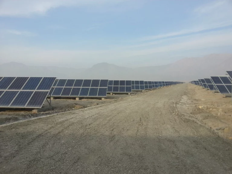
Grid-connected photovoltaic power generation may be separated into centralized power generation using photovoltaics and dispersed photovoltaic energy generation; according to distribution methods, centralized power generation makes use of the vast and steady solar power resources found in desert areas to build massive photovoltaic power stations that are connected with high-voltage transmission systems that power long-distance loads.
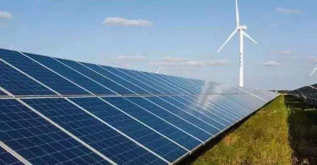
The majority of photovoltaic power plants we can see in photos or videos of unending solar panels in the wild are centralized photovoltaic power generators.
The generation of distributed photovoltaic energy is mainly built on top of land or buildings under which it can be cultivated or planted to address the issue of consumers’ electricity consumption within the area and grid connection to make up for the disparity in the power supply and transmission outgoing.
This kind that generates power is currently the most sought-after.
Since the Centralised PV market share slowly reached saturation and distribution, PV energy generation has become more sought-after.
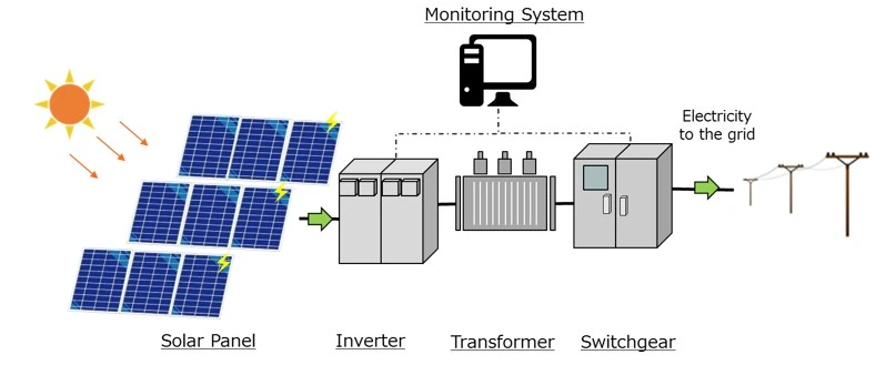
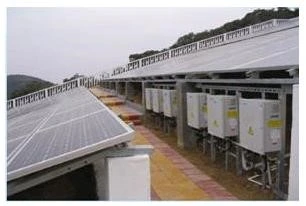
The essential equipment for a distributed solar power generation system comprises photovoltaic cells, square brackets for photovoltaics, box for DC convergence grid-connected DC distribution cabinets, inverters AC distribution cabinets, and various other equipment, as well as power systems monitoring devices as well as environmental monitoring equipment.
When in operation, the solar array used to generate PV energy converts the sun’s energy to electrical energy and then sends it into the distribution cabinet via the sink box and then into the inverter, which reverses the AC power supply to the power required by the design of the building, with any excess power or not enough power being controlled by connection to the grid.
The sun is an endlessly renewable energy source for the entire world. It has the benefits of complete purity, total safety and relative expanse, longevity and maintenance-free, energy efficiency and potential economic benefits, and more. It is a critical element of the long-term strategy for energy.
During the day, the solar cell module produces an electric potential in lighting conditions and sunlight. These are connected in parallel and series to create a solar cell array for its voltage is at the required voltage for the input to the system.
It is recharged by the charge/discharge controller, and the energy converted by the light source is then stored.
In the evening, the battery bank supplies the energy for the inverter. It converts the direct current to alternating current and then transmits that wind to the distribution cabinets, where the switch action of the cabinet supplies the power source.
The battery’s discharge bank can be controlled by the battery controller, ensuring the proper use of the storm.
It is recommended that the PV power station must also be equipped with load-limiting protection and lightning protection devices to safeguard the equipment in the system from overload operation and lightning strikes and to ensure the safety of the equipment.
A photovoltaic system consists of a solar array and battery bank.
It also includes a charger and discharge control, an inverter, AC distribution cabinets, an automated Solar Tracking System, an automated Solar module dust elimination system, and other components.
The function of each component of the system is
In the event of sunlight (either coming from the sun or other bright objects), it absorbs energy from light. This results in it accumulating a different charge on both ends of the battery, i.e., “photovoltaic” voltage “photovoltaic potential” is produced and is an example of the “photovoltaic impact.”
Through the photovoltaic effects, solar cells produce electrical potential on both sides and convert light energy into electrical energy. This is a device for energy conversion.
Solar cells are typically silicon cells divided into monocrystalline silicon solar cells, polycrystalline silicon solar cells, and Amorphous silicon solar cells with three.
Their purpose is to hold the electricity generated by the solar array whenever it’s lit and to provide electricity for the device at any given time.
The essential requirements for the battery pack that is used for solar power cells are
The current solar power generation systems that support batteries are predominantly lead-acid and cadmium-nickel.
With over 200Ah in lead acid batteries generally, it is recommended to select fixed or industrial sealed lead-acid batteries that are maintenance-free. Each battery comes with a nominal at 2VDC.
For lead-acid batteries below 200Ah, typically, you should select a small sealed lead-acid battery that is maintenance-free and sealed. The rated voltage of each battery is 12VDC.
The device will protect the battery from being removed too much or charged too high.
Since the cycle of charges and discharges and the depth of discharge are crucial in determining the battery’s lifespan, charging and discharge control can regulate the battery’s overcharge or discharge.
This is an essential component.
It is a piece of equipment that converts DC power to AC power. Because batteries and solar cells can be considered DC power sources and AC load, an inverter is crucial. By operation mode, inverters are divided into operating inverters that stand independently and grid-connected inverters.
Inverters for standalone use are utilized in standalone solar cell power systems that supply power to various loads.
Inverters that are connected to grids are utilized in solar cells that are related to grids. Inverters are divided into square wave inverters or sine wave inverters based on their output waveforms.
Inverters with square wave patterns have simple circuits and inexpensive costs. However, they possess an enormous harmonic component. They are generally used for systems with less than a few hundred watts and minimal harmonic demands. Sine wave inverters cost more. However, they can be utilized for any load.
Protection functions of the inverter:
Its primary function for the power plant is to switch the standby inverter to guarantee that the system is powered by the same source as the system, as well as the metering function of the line power.
Solar tracking is an electronic device that will keep the solar panel in the direction of the sun throughout the day and let the sun’s light be reflected vertically on the solar panel throughout the day and significantly increase the efficiency of power generation of solar photovoltaic panels.
1. Priority ought to be given to low-loss, self-cooling solar transformers.
2. The capacity of a step-up transformer for the solar power plant can be set following the power output from the array module.
3. Pads with high voltage/low voltage pre-installed and mounted substations or open-type equipment consisting of transformers with low and high voltage electrical components, etc., can be utilized.
In photovoltaic power plants in sandy or coastal areas, the coastal protection class must be IP65 if outdoor structures are employed. Those with protection classes for photovoltaic power plants should be IP54.
4. In-situ step-up transformers for solar power plants can be used with double-winding transformers and split transformers.
5 . In-situ step-up transformer for the solar power plant is recommended to use without the excitation voltage regulator transformer.
In summary, this paper has taken a typical pad mounted transfromer as an example, combined with the characteristics of solar power generation, and analysed in detail its common transformer faults such as grounding, broken wires and short circuits. In order to effectively avoid pad-mounted transformer faults, the solar power plant operation and maintenance side should strengthen the daily insulation monitoring, pay attention to the oil tank laboratory work, and, where conditions allow, also set up additional insulation monitoring devices to ensure the safe operation of the pad mounted transfromer.
Download Resource
Table of Contents Selecting the right pad-mounted transformer requires careful consideration of several critical

The primary function of the pad mounted transformer is to serve as a critical distribution

A pad mounted transformer operates through electromagnetic induction, serving as a crucial distribution component that
After filling in the contact information, you can download the PDF.