ELECTRIC, WITH AN EDGE
In view of the non-effective grounding problem caused by the increased resistance between the panels of the dry-type transformer metal shell after painting, take corresponding equipotential bonding measures.
This article describes the connection between dry-type transformer enclosure panels with grounding cables. In this way, the equipotential connection between the metal movable parts of the dry-type transformer shell is realized, and the electrical safety hazard caused by the dry-type transformer shell to personnel and other equipment may be eliminated when the equipment ground fault occurs.
At the same time, the author gives the selection method of connecting cable section.
The author is a transformer engineer at Daelim. Daelim is a factory with more than 16 years of experience in transformer production and design. DAELIM can provide you with the best quality transformers, including dry-type transformers, pad mounted transformers and power transformers. They can help you effectively save electricity bills and improve power conversion.
Daelim has CSA, ANSI C57.12.00, IEC60076, and other certifications, which means that the Daelim transformers you purchase are in full compliance with your national standards, and the excellent quality can also help you improve your work efficiency.
High Voltage Distribution Transformer
-A lot of electrical companies use high voltage Distribution transformer to effectively operate at applications that are at high voltage levels.
Ultimate Dry Type Transformer for Guide
-This article describes in detail the types, functions, specifications, etc. of dry-type transformers and all the questions about it.
2022 Ultimate Step Up Transformer GuideUltimate Dry Type Transformer for Guide
-This article describes the principle, type, internal structure, installation and other aspects of the step up transformer in detail for you.
Electrical ground fault is one of the most common electrical faults in power systems. When the system is short-circuited, the accessible metal casing of electrical equipment will carry fault voltage.
In order to ensure that the fault voltage will not cause personal injury, the relevant standards require that the exposed conductive parts of electrical equipment must be effectively grounded to ensure that the fault voltage can be reduced below the safe voltage.
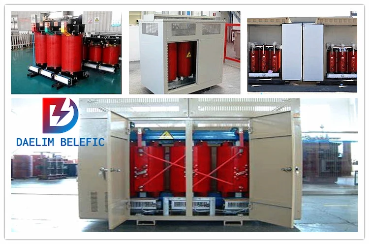
For dry-type transformers, since their windings and electrical terminals are exposed, the national regulations require that they need to be equipped with protective casings in most applications, and the protective casings play the role of electrical fences at the application site.
At present, most of the dry-type transformer casings are assembled by steel plate structure. In order to prevent environmental corrosion, the steel plate casings are sprayed with a certain thickness of paint or other surface treatments.
And the harsher the environment, the thicker the paint on the surface of the steel plate.
According to ISO requirements, the shell paint in the C4 application environment will reach more than 280 μm.
In this case, since the shell panels are connected by bolts, the contact resistance of the contact surface will become very large, thereby affecting the grounding resistance of the entire shell.
In addition, since the dry-type transformer shell is spliced together by multiple steel plates, if the contact resistance between two panels is too large, a fault voltage exceeding the safe voltage may be generated on the two panels when a ground fault occurs in the transformer, threatening personal life. Safety.
Therefore, when designing the dry-type transformer housing, it is necessary to make effective electrical connections to each panel of the housing to reduce the contact resistance, so that the housing as a whole is an equipotential body and eliminates hidden dangers.
The author recommends using the grounding cable or copper braided tape for equipotential bonding of each panel to achieve the above functions, and analyzes and studies the cross-section of the connecting conductors.
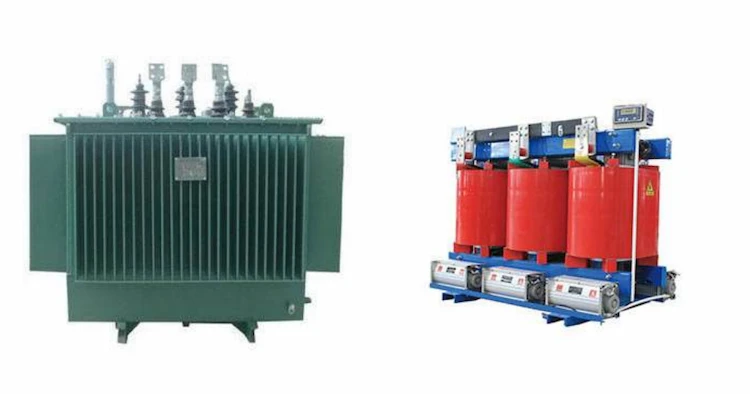
The dry-type transformer shell can be made of stainless steel, aluminum alloy, steel plate and other materials, considering the cost and mechanical strength.
In most cases, dry-type transformers are constructed of painted steel plates.
Depending on the size of the housing, the thickness of the steel plate can be 1.0 mm, 1.5 mm or 2.0 mm.
The surface of the steel plate is treated with painting or electrostatic powder spraying, so that the shell has sufficient anti-corrosion ability to adapt to the use environment of dry-type transformers.
The panels or between the panels and the enclosure frame are assembled by bolts, and each metal panel of the enclosure is produced by welding ground studs at specific locations on the panel.
The grounding stud needs to be protected by painting when the panel is painted to ensure that the surface of the grounding stud is conductive.
The grounding stud can be made of stainless steel or copper. After the housing is assembled, use a yellow-green grounding cable or copper braid to connect the grounding stud of each panel to the adjacent housing panel.
In order to avoid the formation of interfering signals between ground points, it is stipulated that only one ground cable can be connected to each ground point. Therefore, at least two grounding posts should be soldered on each panel for grounding cable connection.
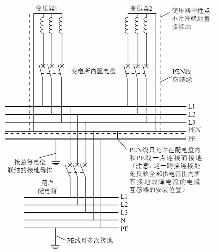
According to the relationship between the neutral point and the PE line, the low-voltage system can be divided into TN, TT and IT systems. Among them, the single-phase short-circuit fault of the TT system and the IT system is not large. In this paper, only the single-phase short-circuit fault of the TN system is used. Take the short-circuit fault current as an example to analyze.
Direct grounding of the neutral point in the transformer room or generator room is not allowed in the IEC standard.
As shown in Figure 2, it is also stipulated that the PEN wire drawn from the neutral point of the dry-type transformer (generator) must be insulated, and can only be connected to the grounded PE busbar at one point in the low-voltage switchboard to achieve system grounding. It must not be grounded elsewhere, otherwise the neutral will return to the power supply through an irregular parallel path.
Since the system below 35 kV is a non-effectively grounded system, the single-phase ground fault current is very small.
Therefore, the influence of the ground current on the high voltage side is not considered in this paper. The contact voltage of the exposed conductive parts of the equipment caused by the low-voltage single-phase ground fault shall not exceed 50 V.
For this reason, the code requires various measures to reduce the grounding resistance at the equipment ground so that the ground-fault voltage of the equipment does not exceed 50 V under any circumstances, thus ensuring personal safety.
Therefore, electrical equipment manufacturers must ensure that the exposed conductive parts of the equipment can be effectively grounded when designing products.
Think of a dry distribution transformer enclosure as a transformer room.
Referring to the requirements of the specification, the dry-type transformer room shall be provided with a general grounding terminal. The general grounding terminal is usually located on the base of the casing. M12 grounding bolts or bolt bases are used as the PE terminals of the casing and the transformer. The grounding terminals of the transformer body and the casing are respectively Connect to the base ground terminal via the green-yellow cable.
Due to the increase in contact resistance after the shell is painted, the resistance between the shell and the total grounding terminal of the dry-type transformer is relatively large.
When a single-phase short-circuit fault occurs in a dry-type transformer, the basic voltage between the short-circuit point and the general grounding terminal of the transformer room may exceed the safe voltage.
Therefore, auxiliary equipotential bonding is required between each panel, that is, grounding cables or copper braided tapes are used to connect each panel through the grounding column on the board, so that an effective electrical connection is formed between the panels.
Because the size of the enclosure of the power distribution transformer is not large, the resistance after the panel is connected with a grounding cable or a copper braid is very small, which can be considered as an equipotential body, that is, the contact voltage of the human body is zero.
Since the dry-type transformer has no PE row, only the PE terminal is arranged at the base, and the distance between the phase row and the PE terminal is large, resulting in a large phase protection impedance.
When the connection between the low-voltage cabinet and the transformer is a cable, the phase wire and the PE wire are arranged in the same cable protection.
Or when the low-voltage cabinet and the transformer are connected by copper bars, the phase row and PE row inside the low-voltage cabinet are usually arranged on the same horizontal or vertical plane.
In both cases, the phase lines and PE lines in the low-voltage cabinet are arranged regularly, so the phase protection impedance in the low-voltage cabinet is very small.
Therefore, when the dry-type transformer casing is short-circuited inside, the connecting cable between the PE terminal of the transformer and the low-voltage cabinet is very short, and the PE connection of the two devices is at the same potential.
At this time, most of the short-circuit fault current will return to the power supply through the PE in the low-voltage cabinet to form a ground fault loop, and the current passing through the dry-type transformer shell panel is very small.
Therefore, the connecting cable between the shells is only used to transfer the potential, and only the mechanical strength of the conductor can be considered when selecting the type.
Inside the transformer casing, the specific requirements for PE conductors, equipotential bonding conductors, etc. are not specifically described in the national standard. The author believes that the “Code for Design of Low-Voltage Power Distribution” requires that it is not part of the cable or not co-located with the phase line. The cross-sectional area of each PE within the same outer shield shall not be less than the following values:
(1) There is protection against mechanical damage, copper is 2.5 mm2, and aluminum is 16 mm2;
(2) Without protection against mechanical damage, provisions of 4 mm2 for copper and 16 mm2 for aluminium may apply in this case.
At the same time, referring to the cross-section requirements of the grounding conductor of the switchboard or enclosure in the DNV specification, the cross-section of the connecting conductor between the enclosure panels can be selected as 4 mm2 to meet the requirements.
However, it should be noted that after the connection between the enclosure panels is completed, it needs to be connected to the main ground terminal of the transformer as a whole.
At the same time, after the dry-type transformer body and shell are assembled, they also need to be connected to the grounding terminal of the transformer base. Referring to the requirements in 3.2.15 of “Code for Design of Low-Voltage Power Distribution” (GB 50054-2011), the cross-sectional area of the connected copper conductor is Should be at least 6 mm2 and 16 mm2 for aluminium conductors.
The connection method between the shell panels described in this paper greatly reduces the overall grounding resistance of the shell from the practical application point of view, and is also convenient to operate in production, which can meet the requirements of effective grounding of the shell.
In other specifications such as Det Norske Veritas, the connection conductor between the frame and the panel is acceptable. Therefore, in the engineering use, the relevant designers can choose the appropriate grounding connection method according to the actual situation.
However, for painting protection or using contact pads to achieve grounding, the author does not recommend it because the damage to the paint may lead to rust and corrosion of the shell panel.
ELECTRIC, WITH AN ENGE-- DAELIM BELEFIC
After filling in the contact information, you can download the PDF.