ELECTRIC, WITH AN EDGE

In daily life, we will use step up transformers when entering the market. Whether it is a large step up transformer or a small step-up transformer.
This article describes the principle, type, internal structure, installation and other aspects of the step-up transformer in detail for you.
Provide you with the most complete reference when purchasing step-up transformers.
If you need to purchase a step-up transformer. Daelim has always been your best choice. Whether it is in cryptocurrency mining farms, hydropower stations, or commercial gathering areas, Daelim has a wealth of cases that can provide your reference.
As a factory specializing in the production of transformers for 16 years, Daelim can provide you with the most professional transformer solutions. And daelim’s transformers have passed the certification of IEEE, CSA, ANSI, DOE, IEC and other professional standards. Rich experience and professional certification can provide you with a reliable guarantee.
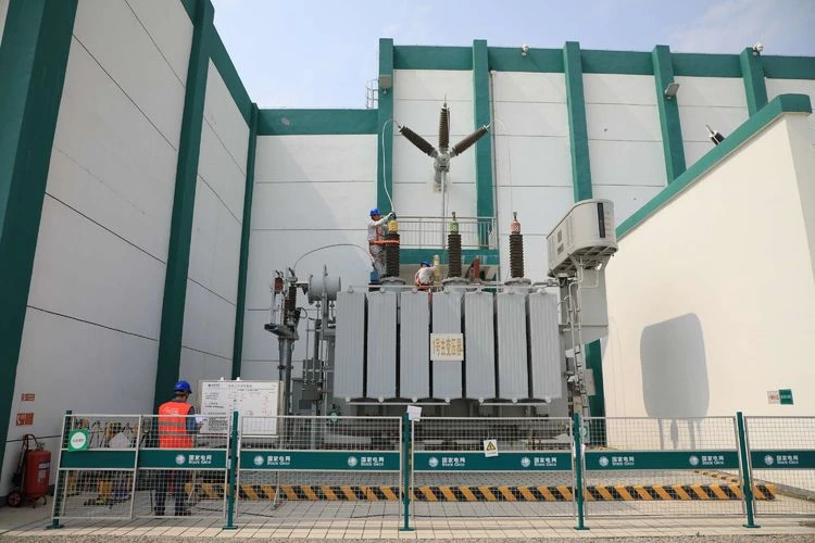
High Voltage Distribution Transformer
-A lot of electrical companies use high voltage Distribution transformer to effectively operate at applications that are at high voltage levels.
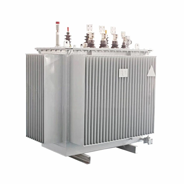
2022 Ultimate Oil Immersed Transformer Guide
-Explains the structure of the Oil Immersed Transformer, the difference from the dry-type transformer, specifications, common faults.
The Best Crypto Mining Farm Guide – Bitcoin Mining Power Supply
-This article describes the policies of crypto mining farms in various countries, Bitcoin Mining Power Supply, and transformer selection.
Transformers only play the role of energy transfer in the process of transformation. No matter whether the transformed voltage is increased or decreased, the electric energy will not increase or decrease.
According to the law of conservation of energy; when ignoring losses, the power P2 output by the transformer should be equal to the power P1 obtained by the transformer from the power supply, that is: P1=P2.
When the transformer is working, the current of the primary and secondary windings is inversely proportional to the primary and secondary rhythm voltage or the number of turns, or is the reciprocal of the transformer voltage ratio.
In fact, the transformer changes the current as well as the voltage. The current transformer is made according to these two principles.
If the primary voltage is higher than the secondary voltage, it is called a step-down transformer, and if the primary voltage is lower than the secondary voltage, it is called a step-up transformer.
Under the conditions of the same frequency and the same capacity, a power transformer can be used as a step-down transformer, and in reverse, it can also be used as a step-up transformer.
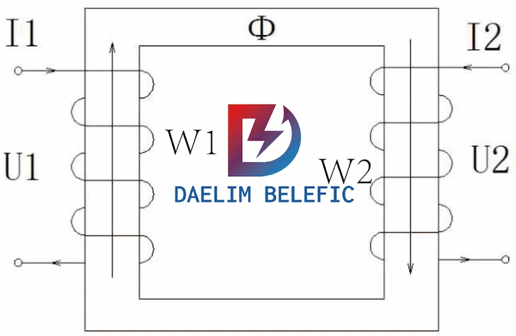
The physical entity running I1 is the primary winding, and the physical entity running I2 is the secondary winding, which is the circuit part of the transformer; Φ is the magnetic field line, and the physical entity where it is located is the iron core, which is the magnetic circuit of the transformer.
When the capacity P (kVA) of the transformer and the number of turns W of the windings are fixed, the magnetic flux Φ (Weber (wb) in the iron core is fixed. Whether a power transformer is used as a step-down transformer or a step-up transformer, the magnetic flux The substance of the road, the iron core, and its physical meaning have not changed.
The transformer is a static electrical appliance that changes the voltage according to the needs of life. Its voltage ratio is equal to the turns ratio. In the above figure: U1/U2=W1/W2.
W1: the number of turns of the primary winding, W2: the number of turns of the secondary winding, a power transformer, W1 and W2 are unchanged.
Therefore, in addition to the grid voltage fluctuation factor, the voltages U1 and U2 are also unchanged.
If the original secondary winding W2 is used as the primary winding W1, then the original primary winding W1 is changed to the current secondary winding W2, the above formula U1/U2=W1/W2 on the contrary U2/U1=W2/W1 is still fully established.
Under the conditions of the same frequency and the same capacity, a piece of electricity can be used as a step-down transformer, and in reverse, it can also be used as a step-up transformer.
A transformer is a common electrical device that can be used to transform an alternating voltage of a certain value into an alternating voltage of another value of the same frequency.
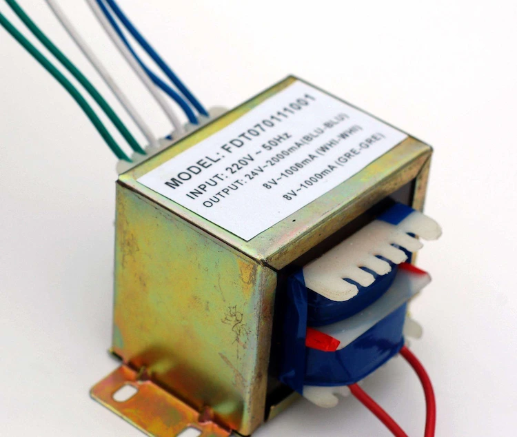
A step up transformer is a transformer used to convert a low-value alternating voltage into another higher-value alternating voltage of the same frequency. It is widely used in high frequency fields, such as inverter power supply.
A step up transformer is a device that converts low AC voltage, large current, and small impedance into high AC voltage, small current, and large impedance.
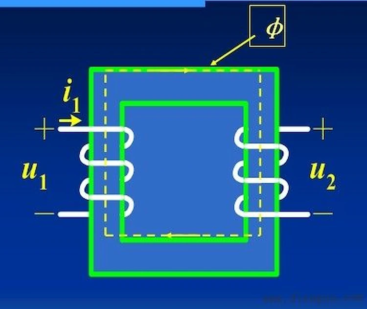
When there is an alternating current in the primary coil, an alternating magnetic flux is generated in the iron core (or magnetic core), which induces a voltage (or current) in the secondary coil.
The input of the step-up transformer must be an alternating power source, and its output voltage is proportional to the turns ratio of the output to input coils.
If you use a battery, because it is DC, you must add a switch circuit to the input circuit to turn it into a constantly changing voltage. In this way, alternating high-voltage electricity can be obtained at the output end.
According to the calculation formula of power and iron core:
S=1.2×root P=1.2×root2000≈54(C㎡)
The cross-section of the selected iron core, 40C㎡, is too small, and it may not be able to accommodate the windings. According to the iron core section 54C㎡ calculation steps:
When the core permeability is 10000 Gauss, the number of turns per volt:
N=45/S=45/54≈0.84 (turn)
The number of turns of the primary 12V:
12×0.84≈10 (turns)
Secondary turns at 800V (influenced by transformer iron loss and copper loss, a 5% margin must be added):
800×0.84×1.05≈706 (turns)
Primary and secondary currents:
I1=P/U=2000/12≈167(A)
I1=2000/800=2.5 (A)
Primary and secondary wire diameters:
D=1.13×Radical I/δ
(The current density is 2.5~3A per square, take 2.5A to calculate)
D1=1.13×root number 167/2.5≈9.2 (MM)
D2=1.13×root number 2.5/2.5=1.13 (MM)
The transformer only works on alternating current. If you use a 4V DC power supply to rise to 220V, you also need an inverter circuit to convert it into a square wave or pulse waveform. This conversion process has a conversion efficiency problem.
When designing, the transformer is a step-down transformer. Considering the loss of the transformer itself, the actual ratio of the number of turns of the primary and secondary is not equal to the theoretical calculation value, but the secondary coil is connected to a certain percentage to increase the number of turns.
Now you want to use the primary and secondary in reverse, you have to consider the supply voltage to increase a certain amount of voltage to achieve your purpose.
The model of a step-up transformer usually consists of symbols representing the number of phases, cooling method, voltage regulation method, winding core and other materials, as well as transformer capacity, rated voltage, and winding connection method.
The meaning of step-up transformer model:
The first letter: O means auto-coupling;
The second letter indicates the number of phases: S is three-phase, D is single-phase;
The third letter: indicates the cooling method, F is oil-immersed air cooling; J is oil-immersed self-cooling; P is forced oil circulation;
The fourth letter: indicates the number of windings, double windings are not marked;
S is three windings; F is split windings;
The 5th letter: Indicates that the wire material L is aluminum wire, and copper wire is not marked;
Digital part: The first one represents the transformer capacity, and the second one represents the voltage level of the transformer. According to SJ-560/10, it should be a 3-phase oil-immersed self-cooling transformer with a capacity of 560KVA and a voltage of 10Kv.
S11 – Transformer model, 11 is the design serial number, energy-saving products. M – fully sealed.
220kVA-indicates that the rated capacity is 220kVA, stacked iron core non-excitation voltage regulating oil-immersed distribution transformer, 220KVA.
S – three-phase
C–cast molding (dry-type transformer) 9 (11)–design serial number 500 (100)–capacity (KVA)
10–rated voltage (KV) m–airtight
The transformer model usually consists of material symbols indicating the number of phases, cooling method, voltage regulation method, winding core, etc., as well as transformer capacity, rated voltage, and winding connection method.
S: Three-phase F: Air-cooled S: Three-winding Z: On-load voltage regulation 9: Design serial number 9;
31500: The capacity is 31500kVA;
110: The rated voltage of the primary side is 110kV;
1. In order to maintain the dielectric strength of the electrostatic generator and the transformer oil installed in the engine, it is usually not allowed to open the observation dialog box and unscrew the surrounding fixed screws to avoid the compressor lubricating oil being damp or dust falling. while reducing the dielectric strength.
2. Check whether the lighting fixtures, heat pipe heat dissipation, and dust collector equipment near the booster transformer are in good condition, and use a clean cloth to wipe off the dust on the booster transformer body and the porcelain bottle.
3. Check the high-voltage load switch on the high-voltage side of the step-up transformer to ensure that the operation is flexible, the touch is good, and the transmission system is partially lubricated.
4. Pull down the high-voltage grounding device knife, check that the grounding device is at the broken part, cover the high-voltage load switch, let the step-up transformer test run, and take out the high-voltage side sign, pay special attention to the disconnection or cover When the step-up transformer high-voltage load switch is performed, there must be about two people on the spot.
5. When it is necessary to replace the new oil, the local power department should help, check the characteristics of the new oil, and stipulate that the compressive strength of its insulating layer is higher than 30000V/2.3mm; and the compressive strength of the oil insulating layer in the engine Should be around 35000V/2.3mm.
6. Use a 3000V shaker to accurately measure the insulation layer resistance of the high-voltage and low-voltage electromagnetic coils of the booster transformer, and confirm that it meets the requirements. When the indoor temperature is 40°C, the high-voltage side of the 1OKV step-up transformer exceeds 30MΩ and the bottom-voltage side exceeds 12MΩ. Before the test, the cable of the grounding device should be connected. After the measurement, the charging and discharging should be carried out.
7.The step-up transformer or the component engine must have excellent wire joints. You should always use an ohmmeter to accurately measure whether the three-responsibility insurance of the casing, the control panel casing, and the external wire joints is connected, and tighten the grounding device anchor bolts. )
At present, the step-up transformers on the market are mainly classified into high-frequency step-up transformers, DC step-up transformers, AC step-up transformers, low-frequency step-up transformers and dry-type step-up transformers.
The high-frequency step-up transformer adopts a high-frequency voltage-doubling rectifier circuit, and applies the latest PWM pulse width modulation technology and power IGBT devices.
According to the electromagnetic compatibility theory, a special process is adopted to make the DC generator high-quality and portable.
It is composed of two parts: the control box and the voltage multiplier. It is equipped with a protective resistor and has the functions of voltage zero-position gate protection, overcurrent and overvoltage protection.
Classification High frequency step-up transformer has the characteristics of small size, light weight, easy portability, convenience, safety and reliability.
It is suitable for on-site DC high voltage test in power sector, DC characteristic test of arrester and other occasions requiring DC high voltage.
The DC step-up transformer has the characteristics of small size, light weight, compact structure, complete functions, strong versatility and convenient use.
It is especially suitable for power systems, industrial and mining enterprises, scientific research departments, etc. to conduct dielectric strength tests on various high-voltage electrical equipment, electrical components, and insulating materials under frequency or DC high voltage. It is an essential and important equipment in high pressure test.
High-quality cold-rolled silicon steel sheets are used for stacking; full oblique joints; special processing technology is used to effectively reduce vibration and noise during operation; and the introduction of new materials, new processes, and new technologies such as computer optimization The transformer is more energy efficient and quieter.
Improving product quality and reliability will be our unremitting pursuit. A large number of basic researches are carried out in quality assurance system and reliability engineering, and reliability certification is actively carried out to further improve the reliability and service life of transformers.
It has heat resistance, moisture resistance, stability, chemical compatibility, low temperature resistance, radiation resistance and non-toxicity.
An AC step-up transformer is a device that transforms AC voltage, current and impedance.
When an alternating current flows through the primary coil, an alternating magnetic flux is generated in the iron core (or magnetic core), which induces a voltage (or current) in the secondary coil.
The AC step-up transformer transformer consists of an iron core (or magnetic core) and a coil. The coil has two or more windings. The winding connected to the power supply is called the primary coil, and the rest of the windings are called secondary coils.
The AC step-up transformer has the characteristics of small size, light weight, compact structure, complete functions, strong versatility and convenient use.
AC step-up transformers are especially suitable for power systems, industrial and mining enterprises, scientific research departments, etc. to conduct dielectric strength tests on various high-voltage electrical equipment, electrical components, and insulating materials under frequency or AC high voltage.
The AC step-up transformer is an essential and important equipment in the high-voltage test.
The low frequency AC step-up transformer core flux is related to the applied voltage.
The field current does not increase as the load increases.
Although the iron core will not saturate when the load increases, the resistance loss of the coil will increase, and the coil will be damaged if the heat generated by the coil cannot be dissipated in time when the rated capacity is exceeded.
If the coil you use is made of superconducting material, the current increase will not cause heat, but there is also impedance caused by magnetic leakage inside the AC step-up transformer.
When the current increases, the output voltage will drop. The greater the current, the lower the output voltage, so the output power of the transformer cannot be infinite.
If you say again, the transformer has no impedance. Then when the transformer flows through the current, it will generate a particularly large electric force, which will easily damage the transformer coil. Although you have a transformer with unlimited power, it cannot be used.
It can only be said that with the development of superconducting materials and iron core materials, the output power of transformers with the same volume or weight will increase, but not infinite!
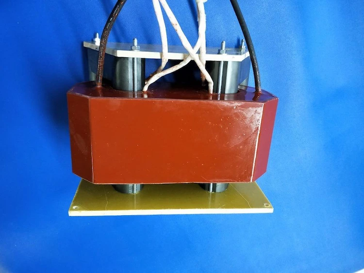
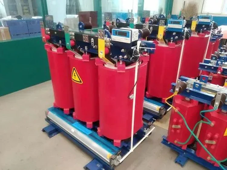
Because the dry-type step up transformer has no oil, there is no fire, explosion, pollution and other problems, so the electrical specifications and regulations do not require the dry-type transformer to be placed in a separate room.
Especially in the new series, the loss and noise have been reduced to a new level, creating conditions for the transformer and the low-voltage screen to be placed in the same power distribution room.
The safe operation and service life of dry-type booster transformers largely depend on the safety and reliability of the transformer winding insulation.
The winding temperature exceeds the insulation withstand temperature and the insulation is damaged, which is one of the main reasons that the transformer cannot work normally.
Therefore, the monitoring of the operating temperature of the transformer and its alarm control are very important. According to the characteristics of the use environment and protection requirements, the dry-type step-up transformer can choose different casings.
IP23 protective casing is usually used, which can prevent solid foreign objects larger than 12mm in diameter and small animals such as mice, snakes, cats, and sparrows from entering, causing vicious failures such as short-circuit and power failure, and providing a safety barrier for live parts.
If the transformer must be installed outdoors, an IP23 protective enclosure can be selected.
In addition to the above IP20 protection function, it can also prevent water droplets within a 60° angle from the vertical line. However, the IP23 enclosure will reduce the cooling capacity of the transformer, so pay attention to the reduction of its operating capacity when selecting it.
There are three ways to use a step-up transformer to make the voltage from 110v to 220v.
1. The first is to use the principle of self-coupling voltage regulator. For example, according to the power of your electrical appliance, choose a 20% larger iron core of the voltage transformer, and wind a step-up transformer yourself. If there are 4 turns per volt, 110V will be wound 440 turns. 440 more turns, so that the two ends have 220V voltage.
2. The second type of isolation booster transformer can be wound, that is, winding 440 turns in thickness, connecting to 110V voltage, and winding 880 turns on the secondary, you can get 220V voltage!
3.The third method is to use inverter. It is not recommended to invert 110V AC here. Unless you are using DC, you can use an inverter to convert 110V DC into 220V square wave AC.
The step-down transformer is a commonly used transformer in the power supply department. For a three-winding transformer, the coils are arranged in the order of high one, one middle and one low, from the outer core.
In the step-up transformer, since the low-voltage side is the primary side, in order to reduce the magnetic flux leakage between the primary and secondary windings and make the reactance distribution more reasonable, the low-voltage winding is placed between the middle and high windings.
This structural difference is mainly reflected in the impedance voltage and load loss.
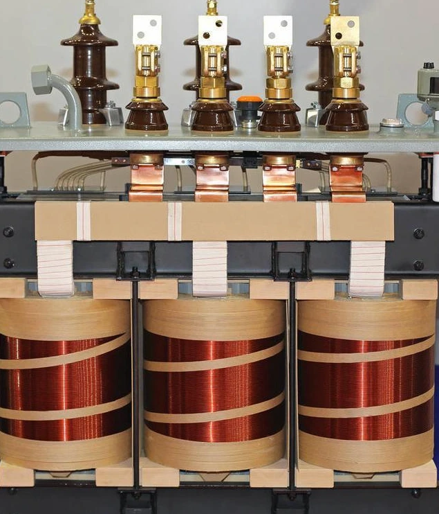
The main internal components of the step-up transformer are: coil, core structure, main insulation, longitudinal insulation and shielding measures.
This article mainly provides your reference by taking the internal structure of the 800kv step-up transformer as an example.
Since it is a single-phase product, the coils are centrally arranged on the main column (1) of the single-phase three-column iron core to reduce the volume and weight.
In the previous transformers of this level, in order to prevent the increase in the volume of the iron core and the high-voltage coil and reduce the leakage flux of the coil, most of the coil layouts adopted the so-called double concentric braid structure, and the high-voltage coil was divided into the line side and the middle. Sexual point side two parts.
The order of their arrangement, starting from the iron core column, is the high-voltage neutral-point side coil, the low-voltage coil, and the high-voltage line-side coil.
However, in this 800kV transformer, in order to increase the iron core, reduce the copper loss, reduce the number of turns, simplify the coil structure, and improve the filling factor, an ordinary double-coil structure that does not divide the high-voltage coil is adopted.
In this way, the cross-section of the core column and the leakage flux of the coil are the same as those of the 1200-1300 MVA three-phase transformer with double concentric arrangement.
However, due to the adoption of the following various new technologies, the product quality is ensured, and the advantages of the ordinary double-coil arrangement are fully utilized.
The voltage regulating coil is no longer wound with an insulating cylinder other than the main coil, but the tap lead is directly drawn from the high-voltage coil to simplify the structure.
The lead-out position of the split-pressing head will increase the leakage flux, resulting in the increase of stray loss and electromagnetic mechanical force.
Therefore, stray losses and electro-mechanical forces were calculated to determine the optimal location of the outgoing taps.
The high-voltage coil adopts a high series capacitive coil with good filling factor and uniform voltage distribution in the coil when it is subjected to lightning impulse voltage.
This kind of coil has excellent lightning resistance characteristics. It is the same as the multi-layer cylindrical coil, which is the standard structure of the high-voltage coil of 500kv transformer.
In particular, the transformers used in substations, which are strictly restricted by transportation conditions and require miniaturized design, almost all use this coil structure.
The winding method of this kind of coil is to wind the coil in two parts: the upper and lower parts, the line end with high voltage is arranged at the center of the electrode shape, and the neutral point with low voltage is arranged at the upper and lower ends of the coil.
In this way, while reducing the insulation distance between the coil and the iron yoke, the electrostatic shielding provided at the upper and lower ends of the coil to ease the electric field is omitted.
When lightning impulse voltage is applied, complex potential oscillation occurs on the voltage regulating coil, resulting in extremely high voltage.
Therefore, using the equivalent loop considering the stray capacitance and inductance in the coil, the potential oscillation in the coil is calculated, the potential oscillation of the voltage regulating coil is mastered, and the insulation structure of the main coil and the voltage regulating coil is determined. .
The coil wire is covered with paper, which can make the section of the unit conductor small without reducing the filling factor and reduce the eddy current loss in the conductor.
The current on the low-voltage coil can also reach 15 kA, so a spiral coil structure composed of more than 150 wires wound in parallel is used.
In order to make the interlinkage leakage flux between the conductors uniform, the conductors are transposed so that there is no circulating current between the parallel conductors.
In addition, in order to prevent the overheating of the tank wall caused by the large current magnetic field on the low-voltage lead, the low-voltage lead between the low-voltage coil and the bushing is divided into two loops, which are respectively connected to the bushing through their own channels.
Due to the high voltage of the 800 kV step-up transformer and the limitation of transportation size and weight, there are two core structures that can be used:
At present, most of the 800 kV transformers are designed as three-column by improving the core structure and material or adopting the outer core technology.
According to the specific conditions of the project, the core of the step-up transformer adopts a three-column structure.
Large-scale iron-core oil-immersed step-up transformers are still dominated by oil-partition insulation structures.
In order to meet the requirements of the insulation performance of high-voltage power transformers, especially for 800 kV step-up transformers, not only the oil-separator structure is required to have a higher breakdown voltage, but also a higher initial partial discharge voltage.
Its main measures are:
The main consideration for longitudinal insulation is to make the initial distribution as close to the final distribution as possible to slow down the coil oscillation and reduce the gradient voltage between the coils.
At present, the power industry mostly adopts external ultra-high voltage step-up transformers or ultra-high voltage step-up transformers.
Wiring or inserting capacitive coils are commonly used, which can control the gradient between the cakes at 8%.
Regardless of the coil, it is desirable that its longitudinal capacitance is adjustable to further reduce the inter-cake gradient.
Due to the large rated current of the transformer in the power station, a large leakage magnetic field will be generated. When the leakage magnetic flux exceeds a certain critical value, the local loss will be high and local overheating will be caused.
A reasonable shielding method can not only reduce impurity loss, but also eliminate local overheating.
The research on the shielding method should also include the metal structure of the high current lead path, and the use of magnetic shunt at the end of the coil.
Some step-up transformers use non-magnetic steel or stainless steel in addition to the pull plate, high-current riser, and low-voltage sloping roof, and some connecting clips also use non-magnetic steel.
It is necessary to study not only whether these components must be made of low-temperature materials, but also their cost, so that they can reflect the comprehensive benefits.
The fuel tank currently adopts a combination of magnetic shielding and electromagnetic shielding.
1) According to the design requirements, the center of the track installation is placed, and the main transformer transportation and the installation of the track in place are completed. The deviation of the track center line to the design center line is ≤ 2mm, the gauge deviation is ≤ 2mm, and the longitudinal unevenness of the track is ≤ 1/1 500mm And the total length is not more than 5mm, the dislocation of the track joint is not more than 1mm, the height difference error of the top surface of the same section is ≤ 2mm, and the data of the track installation should meet the design requirements;
(2) Immediately after the main transformer body arrives, the appearance and internal nitrogen pressure inspection shall be carried out. Make sure that there is no obvious collision and damage to the body; the connecting bolts should be complete, well tightened, and free of leakage; the inflation pressure in the body should be positive pressure and meet the design requirements (0.01 ~ 0.03MPa);
(3)Record and print the “three-dimensional collision recorder” and confirm that there is no collision during transportation (standard ≤ 3g).
1)Check whether each batch of insulating oil tanks delivered to the site is clean and sealed, and whether the factory test records are complete and qualified;
(2)Different grades of insulating oil should be stored separately and marked with obvious signs;
(3) The new insulating oil shall be thermally filtered by the equipment installation unit in the insulating oil depot of the underground powerhouse. After processing, the oil sample shall be sent to the relevant quality inspection unit for testing and full analysis; the sampling test shall be in accordance with the relevant regulations of the current local power oil ,In line with national standards.
During the hauling process of the step-up transformer, the inclination of the long axis of the transformer body is less than 15°, the inclination of the short axis direction is less than 10°, and the speed is less than 15m/s. Adjust to ensure that the center spacing tolerance of each phase is less than or equal to 3mm to meet the design requirements.
(1)The product is a welded structure along the tank edge, which enters the fuel tank from the body entry hole for internal inspection;
(2)When the relative humidity of the environment is less than 75%, the cover can be opened to discharge nitrogen and the internal inspection of the body can be carried out; during the internal inspection, dry air must be blown in until the cover is inspected; the blowing flow can be maintained at 0.2m3 /min or so;
(3)Internal inspectors must wear clean clothes and shoes and socks, and all tools are required to strictly implement the registration and inventory system to prevent forgetting in the box;
(4)The exposure time of the body to the air should be shortened as much as possible, and the maximum exposure time allowed (from opening the cover to destroy the transformer seal until re-evacuating): dry weather (relative air humidity below 65%): 12h; Humid weather (relative air humidity 65% ~ 75%): 8h;
(5)After the inspection of the body, it must be washed with qualified transformer oil, and the bottom of the oil tank must be cleaned;
At the same time as the internal inspection of the body, the installation and wiring of the high-voltage riser and the high-voltage bushing can be carried out
(1) The reassembly of general components (such as water cooler, oil conservator, pressure relief valve, air conduit, etc.) should be completed before vacuum oil filling;
(2) All the joint pipes should be reassembled according to the markings on the pipes when they leave the factory, and the insulating parts to be installed and the cover plate opened by the main body should have dust-proof measures;
(3) When installing the high-voltage bushing, the bolt connection should be firm and reliable to prevent damage to the insulation at the root of the lead due to large tensile force. The lead is not allowed to twist, circle, etc. The tapered part of the lead insulation enters the casing pressure equalizing ball as required by the drawing middle;
(4) Check the tap changer:
The low-pressure channel is divided into two parts a, b-c, and the middle is connected by a metal bellows. Metal bellows are used to connect the low-pressure channel and each body.
Remove the oil level of each single-phase transformer to the bolt connection of the single-phase transformer low-voltage lead connecting wire, and then connect the transition copper bar (the copper bar used to connect the single-phase transformer and the low-voltage channel);
Install the low-voltage channel with each single-phase transformer, connect the two low-voltage channels through bellows, and install the copper bars and transition copper bars between the two channels immediately after the channels are connected;
After the internal wiring of the low-pressure channel is connected, immediately seal the channel manhole cover, and install the three-phase oil pipeline according to the mark marked at the factory, and then use the DN 80 butterfly valve on the upper part of the channel to evacuate. After the vacuum degree is qualified, three-phase simultaneous oil filling is carried out through the DN 80 gate valve at the lower part of the transformer.
(1) The transformer outlet terminal board should be well insulated, the pads of the connection bolts and fixing parts should be firm, and the terminal board should be well sealed without oil leakage;
(2) When installing the rising seat, the nameplate of the current transformer should face the outside of the fuel tank, and the position of the bleeder plug should be at the highest position of the rising seat;
(3) The center of the transformer and the riser should be the same;
(4) The insulating cylinder should be installed firmly, and the installation position should avoid collision with the equipment lead wires.
(1) Before the casing is installed, inspection and tests should be carried out to ensure that the casing, flange neck and inner wall of the pressure equalizing ball are clean; the casing should be sealed reliably, without oil leakage or gas leakage, especially SF6 gas leakage is not allowed into the transformer oil;
(2) When it is confirmed that the internal insulation of the oil-filled bushing has been damp, it should be dried;
(3) The stress cone of the high-voltage bushing cable should enter the pressure equalizing cover of the bushing, and the connection between the lead-out end and the top terminal of the bushing should be in close contact; Structure) The installation of the structure should be carried out in strict accordance with the regulations of the manufacturer;
(3)The gasket of the top structure of the casing should be installed correctly and sealed well. When connecting the lead, the top structure should not be loosened.
Before the insulating oil is injected into the transformer, the insulating oil is dehydrated, degassed and filtered through a vacuum oil filter, and the oil quality must meet the specification requirements.
During the installation of the main transformer, in order to ensure the circulation quality of the insulating oil, vacuum oil injection and hot oil circulation are carried out in two stages:
(1) The installation and connection of the high-pressure riser and the high-pressure bushing are completed, and the single-phase body is filled with oil and the hot oil is circulated for 72 hours;
(2)The low-pressure channel and all accessories are installed, the whole is filled with oil (including the oil conservator), and the hot oil of each phase is circulated for 72 hours.
(1) Before oiling, vacuum the entire transformer first, the vacuum degree should be no more than 0.13kPa residual pressure, and then vacuum oiling can be done after maintaining for 48 hours;
(2) Use the DN 80 gate valve at the lower part of the fuel tank to inject oil, and the oil injection speed should not exceed 6t/h, until the oil tank is full, and the specified vacuum degree should be maintained during the oil injection process;
(3)Continue to maintain the vacuum for 2h, and then the hot oil circulation can be carried out.
(1) Hot oil circulation process.
The oil is heated by the electric heating device of the high vacuum oil purifier, and it is required that after the oil temperature at the outlet of the transformer reaches 70°C, the oil is continuously circulated for 24 hours, and then the oil sample is taken for testing, and the testing results must meet the requirements of “Transformer Oil”;
(2)During the circulation process, the circulation can be guided.
During the hot oil circulation process, open the butterfly valves on the upper and lower parts of the corresponding phase transformers on the oil pipeline connected to the water cooler, and start the submersible oil pump on the water cooler to make the oil conduct guided circulation. In the process of hot oil circulation, a guide cycle is carried out every 4h, and the time is 2h until the end of the cycle.
After the accident oil discharge pipe, low pressure channel and oil conservator are installed, oil is injected after the overall vacuuming is qualified. The specific cycle route is as follows:
(1) The adjustment accuracy of the equipment center and phase spacing should meet the design requirements;
(2) During the internal inspection and internal construction and operation, the entry and exit registration system of tools and equipment should be strictly implemented. After construction, cleaning and inspection must be carried out again. At the same time, ensure that the ambient humidity is less than 70%, and strictly control the exposure time of the body in the air. ;
(3) Strengthen the hot oil circulation and inspection work before the insulating oil is injected into the body to ensure that the insulating oil injected into the equipment is qualified oil;
(3)Before oiling, the vacuum degree of the equipment should meet the requirements of the manufacturer, and vacuum oil replenishment should be carried out; the hot oil circulation time of the equipment should reach the specified time, and oil samples should be taken in time for inspection according to the manufacturer’s requirements.
The loss of the transformer is determined by the performance index of the silicon steel sheet, the quantity of copper material, the structure type and the magnetic shielding or electrical shielding used to reduce the additional loss under the same manufacturing technology conditions.
If you blindly pursue its low loss, it will inevitably be large in size and heavy in weight, and cannot be transported.
Therefore, the loss can only be limited to a certain extent depending on the transport size and transport weight.
The single-phase transformer is not limited by transportation (under a certain capacity), its materials are more available, and the loss is smaller.
The general situation is the same manufacturer, the no-load loss of three single-phase transformers is larger than that of a three-phase transformer of the same capacity, but the total loss is basically the same, and the three-phase transformer is larger.
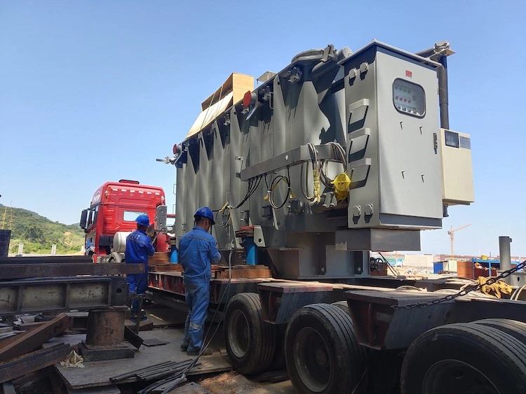
Transporting large transformers, especially step-up transformers with a capacity of 500 MVA and above, is very difficult and is mainly affected by factors such as transport weight, height and width.
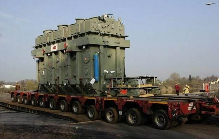
Railway transportation is limited by factors such as bridges, railway load-bearing and railway tunnels. According to the transportation requirements, the normal transportation size (length × width × height) is (6 ~ 9) m × 3.6 m × 4 m, and the transport weight is limited to 195 t.
The transportation size is determined according to the railway conditions passed during transportation, and some are looser than the above-mentioned dimensions.
The use of clamp trucks not only costs for the transformation of the transport vehicles, but also the vehicle speed is limited to (15-20) km/h, which greatly interferes with the normal transport capacity of the railway.
The cost of bridge reinforcement and other costs is very large.
If the power plant is built on the seaside, the imported transformers, whether three-phase or single-phase, can be transported without problems, while the domestic transformers depend on the transportation situation from the manufacturer to the adjacent seaport.
For power plants built beside or near inland rivers, the transportation of large-capacity transformers is affected by factors such as wharfs, floating cranes, bridges, and ship drafts.
If the draft depth is not enough, it is necessary to dredge the river channel so that the river channel can pass through the ships transporting transformers; the unloading terminal should be widened and lengthened, and the foundation should be strengthened; if the lifting capacity is not enough, it is necessary to rent lifting equipment from other places; the bridge and the water surface height are not enough and need to be renovated, etc.
This series of costs must be considered when selecting a transformer unit and a field investigation should be done.
Road transportation is limited by factors such as bridges, roadbeds, and transportation vehicles.
Bridge reinforcement costs, road widening and road reconstruction costs should all be calculated into the transformer’s one-time investment for comparison.
Transformer accident, especially the step-up transformer, such as the step-up transformer accident of 600MW unit, suddenly throws off the 600 MW load, not only has a great impact on the generator, but also on the power system.
The light ones cause large-scale power outages;
In severe cases, due to the sudden load shedding of 600 MW and the shortage of system spare capacity, the frequency of the system will drop, jeopardizing the stability of the power system, and in severe cases, the system will collapse, and the loss cannot be estimated.
If the transformer needs to be returned to the factory for repair after an accident, the repair fee will be (60-70)% of the original price.
The round-trip transportation and miscellaneous costs of three-phase transformers are much more expensive than that of single-phase transformers. Relatively speaking, single-phase transformers are more convenient to transport and repair.
In the event of an accident in a step-up transformer, the cause of the accident must be analyzed first, and the responsibility should be clarified before discussing who repairs it. The longer the delay, the greater the loss.
Purpose of Step-Up Transformer: The main function of a step-up transformer is to increase the voltage from a lower value to a higher value. It's widely used in power distribution to send electrical energy over long distances.
Difference with Step-Down Transformer: Unlike a step-up transformer, a step-down transformer decreases the voltage. The step-up transformer and step-down transformer difference lies in their winding ratios.
Windings: The step-up transformer has more turns on the secondary winding compared to the primary. A step-down transformer has the opposite configuration.
Applications: Step-up transformers are often used in power plants, while step-down transformers are common in residential areas.
Efficiency: Both types aim for maximum efficiency, but the design considerations vary.
Safety Considerations: Special care must be taken when dealing with high voltages in step-up transformers.
Cost and Availability: Both types of transformers are widely available, but their prices may differ based on specifications.
Step-Up Transformer for Solar Power Plant: This is a specialized application where the transformer is used to increase the voltage generated by solar panels.
Energy Transmission: Step-up transformers are essential in the energy transmission across the grid.
Conclusion: Understanding the differences between step-up and step-down transformers is crucial for selecting the right type for specific applications.
Introduction: Designing a step-up transformer for solar power plants requires careful planning and consideration of various factors.
Voltage Requirements: Determining the necessary voltage increase is the first step in the design.
Solar Panel Output: The transformer must be compatible with the solar panel's output specifications.
Efficiency Considerations: Selecting materials and winding ratios that provide optimal efficiency.
Cooling System: Solar power plants may require specialized cooling systems for transformers.
Regulatory Compliance: The design must comply with local regulations and standards such as ANSI, IEEE, and others.
Cost Considerations: Balancing performance and cost is crucial in the design process.
Environmental Impact: Consideration of environmental factors like weather and location.
Integration with the Grid: Ensuring seamless integration with the existing power grid.
Conclusion: Designing a step-up transformer for a solar power plant requires a holistic approach that considers all aspects of the application.
Primary Winding: This is where the input voltage is applied. It has fewer turns in a step-up transformer.
Secondary Winding: It has more turns and is responsible for stepping up the voltage.
Core: Made of iron or ferrite, the core's purpose is to provide a path for magnetic flux.
Insulation: This prevents short circuits between windings.
Cooling System: To dissipate heat generated during operation.
Tap Changer: Allows for adjusting the voltage ratio.
Terminals: Connection points for input and output voltage.
Step-Up Transformer Diagram: Below is a simplified representation.
| Primary Winding | Secondary Winding | Core | Insulation | |—————–|——————-|——|————| | Fewer Turns | More Turns | Iron | Required |
Applications: Understanding the components helps in various applications like step-up transformer 110v to 220v.
Conclusion: The key components of a step-up transformer are essential for its proper functioning and must be understood by engineers and technicians.
Voltage Calculation: The voltage transformation is governed by the ratio of turns in the secondary to primary windings. Formula:
[ V{\text{secondary}} = \left(\frac{N{\text{secondary}}}{N{\text{primary}}}\right) \times V{\text{primary}} ]
Current Calculation: Current is inversely proportional to voltage in a transformer. Formula:
[ I{\text{secondary}} = \left(\frac{N{\text{primary}}}{N{\text{secondary}}}\right) \times I{\text{primary}} ]
Efficiency Factor: Real-world transformers are not 100% efficient, and the formula must consider losses.
Example: A step-up transformer 110v to 220v with 100 turns on primary and 200 turns on the secondary.
Applications: The formulas are widely used in designing and troubleshooting transformers.
Safety Considerations: Accurate calculations are vital for safe operation.
Advanced Models: More complex models consider factors like resistance and reactance.
Software Tools: Many engineering software tools can assist in these calculations.
Real-world Adjustments: Considerations for manufacturing tolerances and operational variations.
Conclusion: The step-up transformer formula plays a vital role in design, analysis, and operation, allowing engineers to predict performance accurately.
Power Distribution: Stepping up voltage for long-distance transmission.
Industrial Applications: Used in machinery that requires higher voltage, such as the step-up transformer 208 to 480.
Consumer Electronics: Small transformers in devices like microwave ovens.
Solar Power Plants: To connect to the grid at the required voltage level.
International Travel Adapters: Such as step-up transformer 110v to 220v for travelers.
Medical Equipment: Used in devices like X-ray machines.
Oil and Gas Plants: Specialized applications in energy sectors.
Education and Research: Used in laboratories and educational institutions.
Price Considerations: Different applications may have various cost considerations for the step-up transformer price.
Conclusion: From power grids to consumer products, step-up transformers are integral to modern life, providing flexibility in voltage transformation.
Capacity: The power rating directly influences the price.
Materials: Quality of materials like copper and iron.
Cooling System: Different cooling methods may affect the cost.
Brand: Established brands may command higher prices.
Regulatory Compliance: Meeting international standards like ANSI, IEC can increase costs.
Customization: Customized solutions tailored to specific needs may be more expensive.
Location: Geographic location and transportation costs.
Warranty and Support: Post-sale services may affect the overall cost.
Quantity: Bulk purchases may offer discounts.
Conclusion: Understanding the factors influencing the step-up transformer price can guide buyers in making informed decisions that match their budget and requirements.
Introduction: The step up transformer 208 to 480 is a specific type designed for industrial applications.
Usage in Machinery: Many industrial machines require 480 volts, so this transformer enables compatibility.
Energy Efficiency: Designed to minimize energy loss in industrial environments.
Safety Features: Includes features like overload protection and robust insulation.
Regulatory Compliance: Built according to industrial standards.
Cost Considerations: Balanced to provide performance at a reasonable price.
Maintenance: Ease of maintenance is often a design consideration.
Customization: Can be tailored to specific industrial needs.
Availability: Readily available from reputable suppliers like Daelim.
Conclusion: The step up transformer 208 to 480 is a critical component in modern industry, allowing for versatile power usage while maintaining efficiency and safety.
Definition: An isolation transformer isolates circuits from each other, providing safety and noise reduction.
Similarities with Step-Up Transformers: Both can change voltage levels, though the isolation transformer often does it without changing the voltage ratio.
Usage in Step-Up Applications: An isolation transformer can also function as a step-up transformer if designed that way.
Safety Applications: Used to protect sensitive equipment and prevent electric shocks.
Noise Reduction: Helps in reducing electrical noise in sensitive applications.
Compatibility: Often used in conjunction with step-up transformers in complex systems.
Cost Considerations: Generally more expensive due to additional safety features.
Standards and Regulations: Must meet specific safety standards.
Examples: Used in medical equipment, audio systems, and laboratory instruments.
Conclusion: Isolation transformers play a complementary role with step-up transformers in various applications, adding an extra layer of safety and functionality.
Power Grid: Step-up transformers are used in power plants to raise the voltage for long-distance transmission.
Electric Trains: In rail systems, to adapt to different voltage requirements.
Medical Devices: Like MRI machines that require precise voltage control.
Solar Power Plants: Step-up transformers help integrate solar power into the grid.
Consumer Products: Like the step up transformer 110v to 220v used in travel adapters.
Educational Institutions: In physics labs to demonstrate electrical principles.
Industrial Machines: Including the specific step up transformer 208 to 480 for industrial applications.
Automobile Industry: In electric vehicle charging stations.
Oil and Gas Sector: Specialized applications in refineries and drilling rigs.
Conclusion: Step-up transformers are ubiquitous, playing a crucial role in diverse applications across various sectors, contributing to modern life's efficiency and convenience.
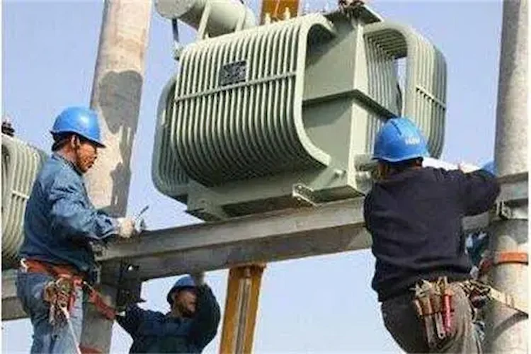
Site Preparation: Choosing a suitable location that complies with regulations and standards.
Installation Guidelines: Following the manufacturer’s guidelines, such as those provided by Daelim.
Electrical Connections: Properly connecting primary and secondary windings according to specifications.
Cooling System Setup: If applicable, ensuring the cooling system is correctly set up.
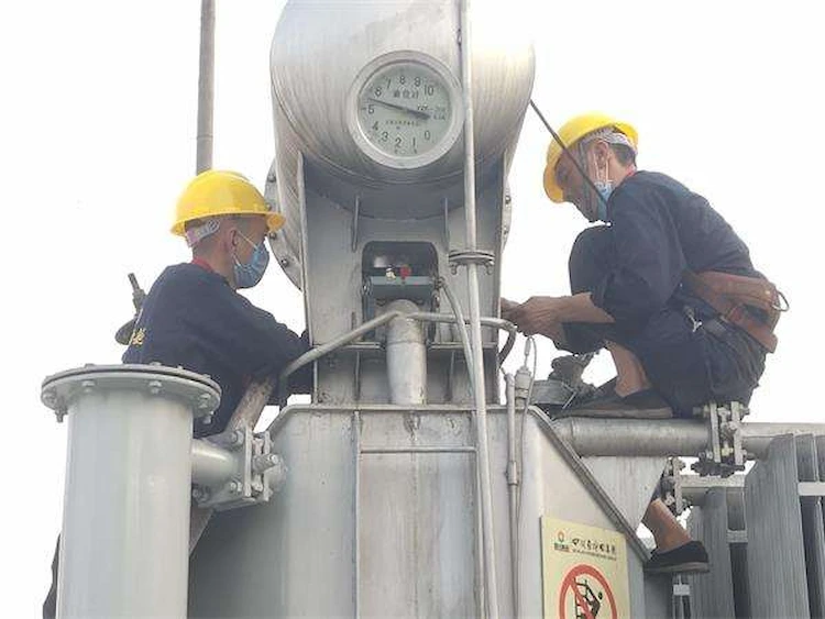
Safety Precautions: Using appropriate protective gear and adhering to safety regulations.
Regular Inspections: Regularly inspecting for wear and tear, including insulation and cooling systems.
Maintenance Schedule: Adhering to a regular maintenance schedule for optimal performance.
**Trou
bleshooting**: Identifying common issues and knowing how to resolve them or when to call for professional assistance.
End-of-Life Procedures: Properly decommissioning and recycling the transformer at the end of its life.
Conclusion: Proper installation and maintenance are vital for the efficient operation and long lifespan of a step-up transformer. Adhering to best practices ensures that the equipment serves its purpose reliably and safely.
ELECTRIC, WITH AN ENGE-- DAELIM BELEFIC
After filling in the contact information, you can download the PDF.