ELECTRIC, WITH AN EDGE
At the forefront of power distribution and energy solutions, DAELIM emerges as a leading UL-listed transformer manufacturer. Renowned for their specialty in American standard transformers, DAELIM has pioneered innovations in the realm of power transformation. Within this extensive realm lies a diverse portfolio, ranging from Pad Mounted Transformers to High Voltage Power Transformers.
Spanning over two decades, DAELIM has garnered unmatched experience in national transformer projects. The technical marvels housed within their teams ensure that their solutions aren’t just products – they are tailored experiences. Every solution echoes the commitment to excellence, resonating with the diverse needs of utilities, data centers, renewable power plants, and more.
Delving into the depths of their offerings, DAELIM proudly showcases a range:
Every product they shape stands as a testament to DAELIM’s unwavering commitment to the stringent UL standards, aiming always for the zenith of excellence.
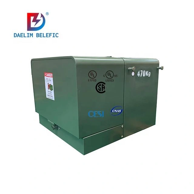
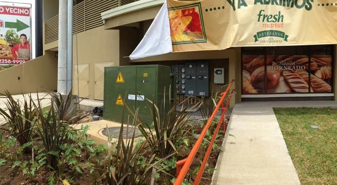
In the bustling landscapes of Minnesota’s commercial sectors, the need for reliable power distribution is paramount. DAELIM addressed this demand by introducing their Single-phase pad-mounted transformers.
| Specifications | Details |
|---|---|
| Transformer Type | Single-phase pad-mounted |
| Quantity | 40 Units |
| Certificate | UL |
| Frequency | 60 Hz |
| Voltage | 12470/7200-120V |
Ensuring they stand tall against varying temperatures, these transformers are designed to maintain their nominal kVA rating. Compliance with IEEE C57.12.00 standards ensures reliable and consistent performance.
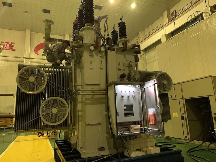
Navigating to the industrial terrains of Vancouver, DAELIM’s expertise was sought for an impactful solution. The requirement? Power transformers that don’t just distribute – they empower.
| Technical Data | Details |
|---|---|
| Rating | 12000kVA |
| Primary Voltage | 66000V |
| Secondary Voltage | 12470Y/7200V |
| Frequency | 60Hz |
| Impedance(ONAN) | 6.50% |
Crafted with copper windings and meeting a host of IEEE standards, these transformers are the lifeline of the industries they serve.
Be it a data center pulsating with data streams or an energy storage unit brimming with potential – DAELIM's solutions are as diverse as the industries they serve. Their offerings don't just align with international standards; they redefine them.
Choosing DAELIM is synonymous with choosing excellence. With every UL-listed product, a promise of safety and unmatched performance is delivered. The reflection of this commitment is evident in their international presence and robust after-sales service system.
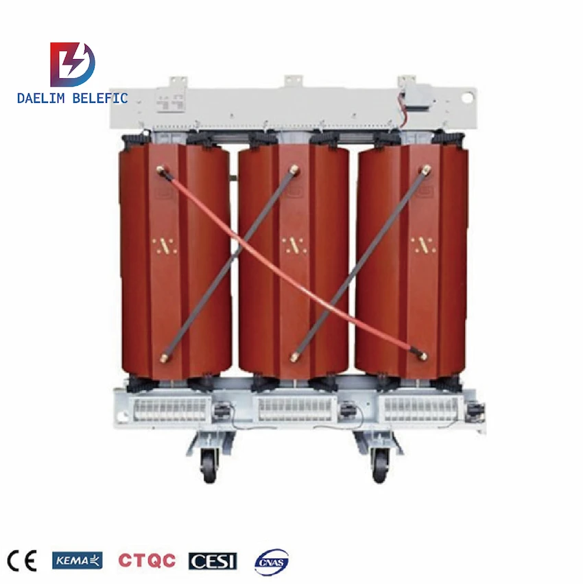
This is an electrical construction project for a government office building. Since the purchaser’s energy-saving assessment indicators are strict and the design also needs to consider the operation and maintenance costs of the building after the completion of the building, dealim has conducted a comprehensive analysis of the power load of its substation low-voltage system and passed the comprehensive energy efficiency cost method (TOC method) ) Calculated and compared the commonly used Three Phase Epoxy-resin Dry-type Transformer and S(B)H15-M Series Sealed Amorphous Alloy Transformer economic evaluation indicators as the basis for subsequent selection of transformers.
This project has a 22/0.4kV independent substation. The construction party is responsible for introducing two independent 22kV medium voltage external lines buried into the medium voltage distribution room.
Two dry-type transformers are installed in the substation to operate in series, each with 50% load during normal operation, and when one power supply fails, the other with full load.
According to the stability of the local power system and the requirements of foreign parties, two diesel generators with a common power of 1 000kVA are set up in parallel as a backup power source to provide full load power protection for the project in the event of a mains failure.
All fire-fighting equipment, broadcasting and conference systems, security equipment, emergency evacuation lighting, office area electricity, elevators, weak current system computer rooms, relay power supplies, life pumps, and sewage pumps are the primary loads of this project. Among them, the auditorium and reception hall lighting, electricity Power consumption for sound, video and computer systems is a particularly important load among the first-level loads; power consumption for air-conditioning is a second-level load; and water fountains and landscape lighting are third-level loads. The schematic diagram of the low-voltage main wiring scheme of this project is shown in Figure 1.
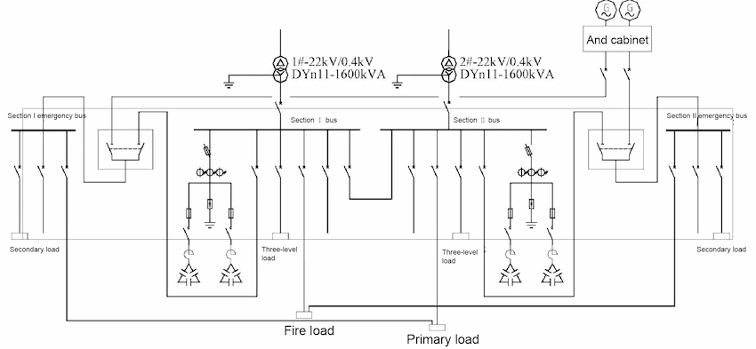
The total load capacity of this project is Pe =2607kW, of which the first-level load is Pe=1422kW, the second-stage load is Pe=1110kW, the third-stage load is Pe=75kW, and the fire-fighting load is Pe=238.5kW.
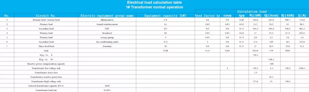
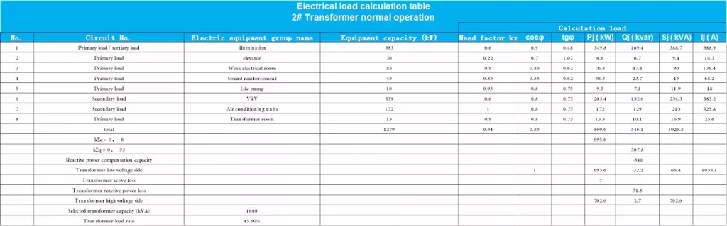
The load calculation table is shown in Table 1, Table 2, and Table 3.
It can be seen from Table 1, Table 2, and Table 3 that this project plans to select two 1600kVA transformers, the normal operating load rate of 1# transformer is 45.6%, the normal operating load rate of 2# transformer is 43.5%, and when one transformer fails, The foreign party requires another transformer to carry all the first, second, and third stage loads of the project for calculation, and the load rate is 94.6%.
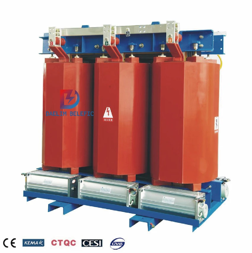
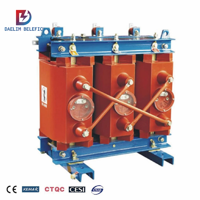
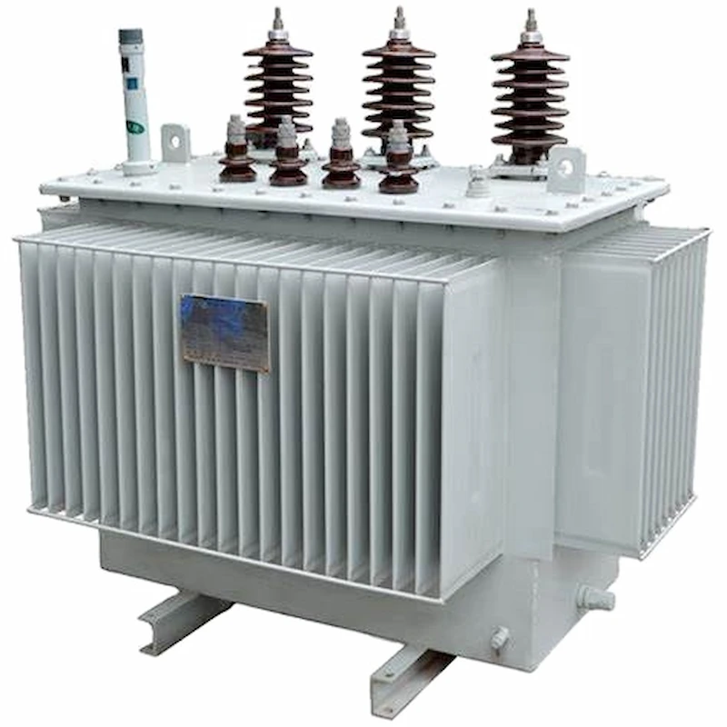
Regarding the choice of transformer capacity, whether it is reasonable or not, and which one to choose for the currently commonly used Three Phase Epoxy-resin Dry-type Transformer and S(B)H15-M Series Sealed Amorphous Alloy Transformer.
According to the actual situation of the project, Daelim will comprehensively consider technical and economic factors such as transformer load rate, price, loss, load characteristics, and electricity price to conduct an energy efficiency evaluation as the basis for the next design.
The efficiency of the transformer η
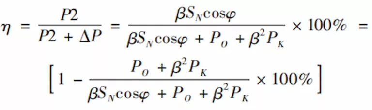
Where P2 is the load power; ΔP is the active loss (including iron loss and copper loss); cosφ is the load power factor; β is the load factor; SN is the transformer rated capacity; Po is the no-load loss of the transformer; PK is the transformer’s Short circuit loss.
In order to find the best transformer load factor, use advanced mathematics to find the first derivative of the above formula and make it equal to zero. When dη /dβ = 0, we get:
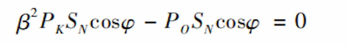
Calculate the active economic load factor βmp when the transformer operating efficiency is maximum without considering the reactive power loss of the transformer,
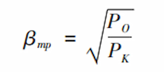
It is not difficult to see from the above equation that when the constant loss (iron loss) of the transformer is equal to the variable loss (copper loss), the operating efficiency of the transformer is the highest.
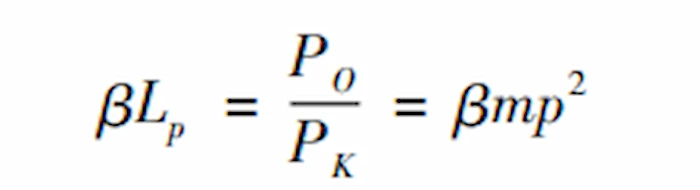
The critical load factor βLp when the transformer is operating at the lower limit of the economic operation zone (that is, the large horse-drawn trolley) is:
Comprehensive energy efficiency cost method (TOC method)
For the economic evaluation of the energy efficiency of the distribution transformer, the comprehensive energy efficiency cost method (TOC method) that comprehensively considers its initial investment and the power loss cost to be paid during its economic use period can be adopted.
The calculation expression of the comprehensive energy efficiency cost of the distribution transformer is:
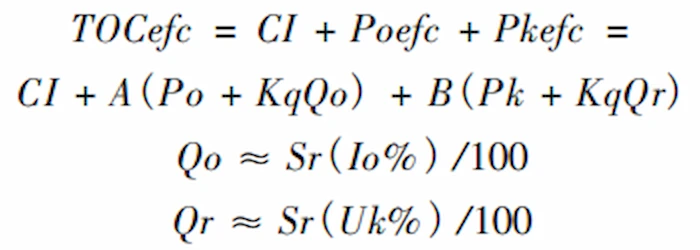
In the formula, CI is the initial cost of the distribution transformer, A (Po + KqQo) is the equivalent cost of transformer no-load loss, and B (Pk + KqQr) is the equivalent cost of transformer load loss.
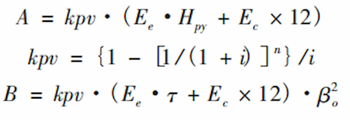
The A value is not only related to the life of the transformer and the interest rate during this period, but also related to the electricity price.
The B value is not only related to the aforementioned A value related factors, but also related to the load characteristics of the load carried by the transformer. The calculation formula is as follows:
In the formula, CI is the initial cost of the distribution transformer, and the new project is the equipment price (RMB); Poefc is the equivalent cost of the no-load loss of the transformer, (RMB);
Pkefc is the equivalent cost of transformer load loss, (RMB); A is the capital cost of unit no-load loss during the life of the transformer, (RMB/kW);
B is the capital cost of unit load loss during the life of the transformer, (RMB/kW);
Po is the no-load active power loss (iron loss) of the transformer, (kW);
Kq is the economic equivalent of reactive power, generally 0.1kW/kVar, (kW/kVar);
Qo is the reactive power loss when the transformer is no-load, (kVar);
Io% is the percentage of the transformer no-load current to the rated current (%);
Sr is the rated capacity of the transformer, (kVA);
Pk is the active power loss of the transformer load, (kW);
Qr is the increment of reactive power loss at rated load of the transformer, (kVar);
Uk% is the percentage of the transformer impedance voltage to the rated voltage, (%).
kpv is the limit coefficient with a discount rate of i and a service life of n years; Ee is the electricity cost per unit of electricity, (yuan/kWh); the project is located in a city in Southeast Asia, and its operating electricity cost is zero. 118 4USD/h, approximately equal to RMB 0. 75 yuan/h. Ec is the electricity cost per unit capacity, (yuan/kW·month);
Hpy is the annual live hours of the transformer, usually 8 760h; β0 is the initial load rate of the transformer. The initial load rate of this project is based on the data in the load calculation table and is taken as 46%; τ is selected according to the “Industrial and Civil Power Distribution Design Manual”, and the calculated value for urban life is 1 250h.
According to the analysis of Daelim’s transformer technical parameters, the active economic load rate and critical load rate of the Three Phase Epoxy-resin Dry-type Transformer and S(B)H15-M Series Sealed Amorphous Alloy Transformer are shown in Table 4 and Table 5.
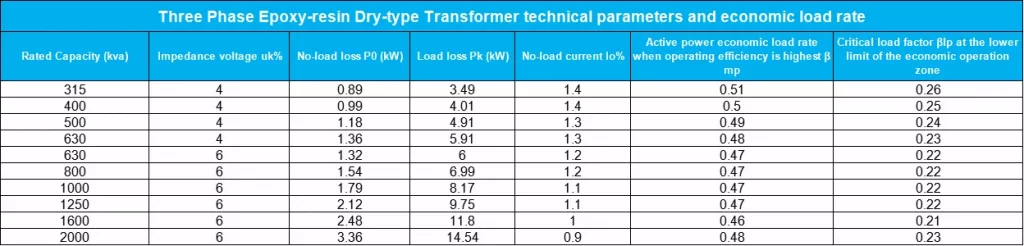
From the above calculation results, it can be seen that the SCB10 epoxy resin cast three-phase dry-type transformer with a capacity of 1 600kVA has the highest operating efficiency when the active economic load rate is 46%, and the critical load rate is 21% when it is in the lower limit of the economic operation zone.
The SCBH15 low-loss amorphous alloy transformer with a capacity of 1 600kVA has the highest operating efficiency when the active economic load rate is 25%, and its critical load rate is 6% when it is at the lower limit of the economic operation zone.
In recent years, various series of low-loss power transformers have been widely used, and significant economic effects have been achieved in terms of saving power and operating costs.
At present, the rated efficiency of the transformer itself is already very high. Generally, the rated efficiency of small and medium-sized transformers is above 96%.
However, in many occasions, the actual operation efficiency of the transformer is not high due to the unreasonable configuration and operation of the transformer.
When the load factor of the transformer is too low or too high, the proportion of the total consumption of the transformer itself in the total input energy of the transformer increases, resulting in a decrease in the actual operating efficiency.
Affected by the traditional habits in the past, many designers and drawing reviewers still have some misunderstandings in the selection and operation of transformers, which leads to a lot of power waste in the practical application of transformers.
For example, the highest efficiency of the transformer appears at about 75% load rate, and the transformer load rate is less than 30%. There is no basis for calculation. It can be seen from the above that the active economic load rate and criticality of transformers of different series and different parameters The load factor values are also different.
Therefore, for the two 1 600kVA transformers installed in this project, the load rate is 43% to 46% during normal operation, and the load rate is 94% during fault operation. 6%, the choice is reasonable.
According to the comprehensive energy efficiency cost method (TOC method) introduced above, Daelim used the transformer service life to be 10 years and 20 years to calculate the power loss costs that the transformer will pay during its economic use period, and consider its initial investment. From an economic point of view, understand and evaluate the energy-saving benefits of transformers more scientifically.
While paying attention to the energy-saving effect, this project also pays great attention to the feasibility and convenience of long-term commitment to daily maintenance and regular overhaul of large equipment.
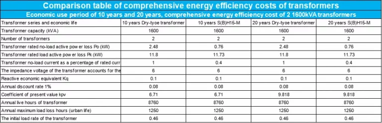
It can be seen from Table 6 that according to the load rate of this project during normal operation, the load rate is 46%. Comprehensive energy efficiency analysis: S(B)H15-M Series Sealed Amorphous Alloy Transformer has a comprehensive energy efficiency cost of 1 159 274 during the 10-year economic use period. RMB, 14% higher than the commonly used Three Phase Epoxy-resin Dry-type Transformer.
The comprehensive energy efficiency cost during the 20-year economic use period is 1 251 557 RMB, which is higher than the commonly used Three Phase Epoxy-resin Dry-type Transformer. 2. 4%.
S(B)H15-M Series Sealed Amorphous Alloy Transformer has low loss and significant energy-saving effect. The rated no-load loss is only about 30% of the Three Phase Epoxy-resin Dry-type Transformer.
The rated no-load loss is only about 30% of the Three Phase Epoxy-resin Dry-type Transformer.
If the initial investment is ignored, the operating cost of the S(B)H15-M Series Sealed Amorphous Alloy Transformer during the 10-year economic use period is 7% lower than that of the commonly used Three Phase Epoxy-resin Dry-type Transformer, and within the 20-year economic use period The operating cost is 17% lower than the commonly used Three Phase Epoxy-resin Dry-type Transformer.
As the project is located in Southeast Asia, the large-scale power distribution products of the recipient countries are mainly purchased from surrounding developed countries and China. Routine maintenance can generally be undertaken by themselves, but regular overhauls must be sent professional and technical personnel from the above-mentioned national maintenance sites.
Therefore, there is no difference in the convenience of maintenance when selecting large equipment, and there is no regional barrier when choosing S(B)H15-M Series Sealed Amorphous Alloy Transformer.
So finally Daelim recommends the use of S(B)H15-M Series Sealed Amorphous Alloy Transformer for customers.
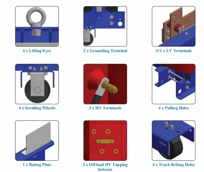
A Complete Guide to Epoxy-resin Three Phase Dry Type Transformer
When you need to find more than just existing transformers, Daelim’s Transformer Service Center can help you design and produce distribution transformers that meet your unique needs.
We have our own factory and a professional team of engineers, which can design and modify application requirements that meet all your conditions.
Download Resource
ELECTRIC, WITH AN EDGE-- DAELIM BELEFIC
After filling in the contact information, you can download the PDF.