ELECTRIC, WITH AN EDGE
Daelim crafts specialized transformer solutions designed specifically for renewable power plants. Their expertise ensures that energy flows seamlessly and efficiently to the grid.
Multiple success stories across diverse markets vouch for Daelim’s dedication and prowess in the renewable energy domain. They don’t just promise; they deliver.
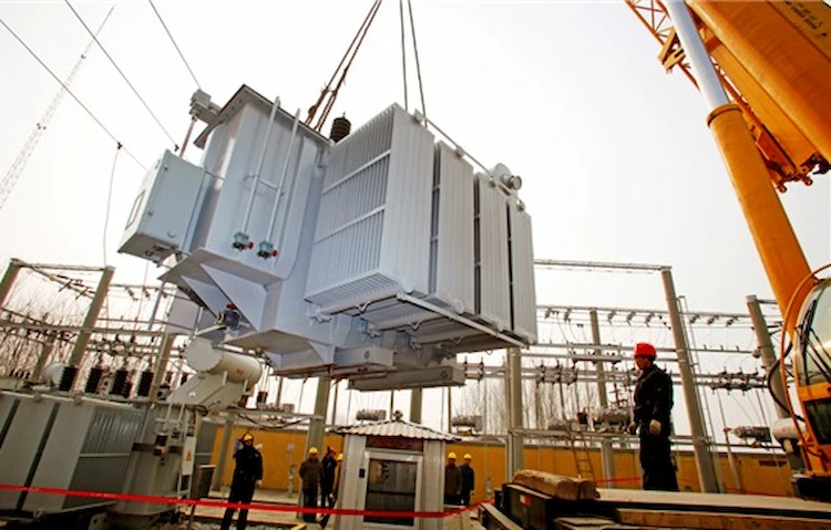
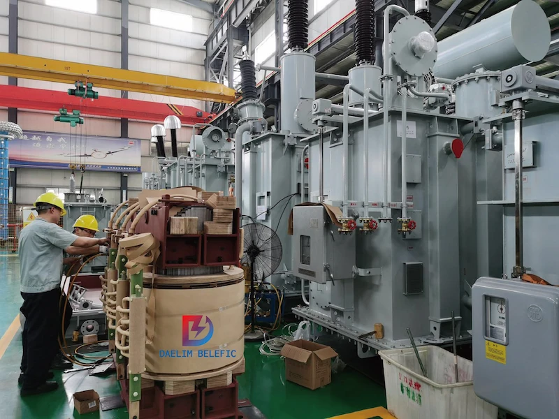
Daelim understands the gravity of real-world scenarios. Their reliance on authentic data and real-use cases ensures that their transformer solutions aren’t just theoretically sound, but are battle-tested and proven. Daelim transformers are built to withstand the rigors of genuine demands, promising both longevity and top-tier performance.
From various energy capacities to intricate technical specifications, Daelim brings a range of transformer solutions to the table, meeting every project’s unique demands.
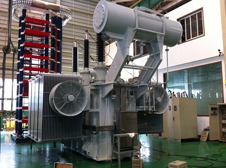
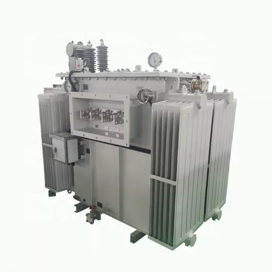
This power transformer is the epitome of reliability. With its superior cooling capabilities and high-voltage windings, it stands as an efficient beacon for energy transfer.
Quantity:2
Type:Oil-Filled, Outdoor, Station Type, Power Transformer
Continuous Rating:16.2 / 21.6 / 27 MVA
Cooling Class: ONAN/ONAF1/ONAF2
Temperature Rise: 65°
HV Winding: 46 kV
LV Winding: 34.5 kV
Tertiary:13.8 kV
Frequency: 60Hz
Winding Material HV/LV: Copper/Copper
Coil Construction: Detailed Description By Vendor
Impedance, at ONAN Rating: 8.5%
Tap Changer: 5 positions De-energized
HV Bushings Location: Top Cover
Ambient Temperature: -20°F-110°F
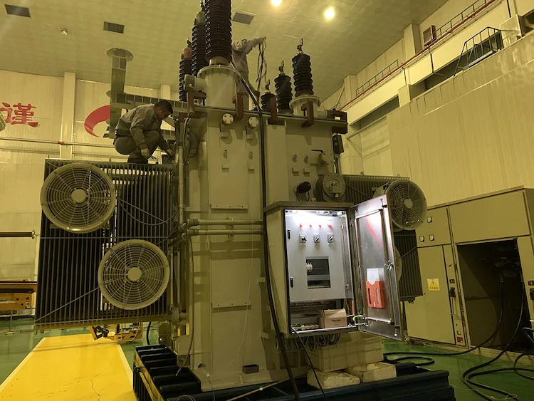
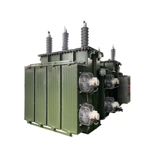
Quantity:1
Type:Oil-Filled, Outdoor, Station Type, Power Transformer
Continuous Rating:50/67/83 MVA
Cooling Class: ONAN/ONAF1/ONAF2
Temperature Rise: 65°
HV Winding: Gnd Wye 138 kV
LV Winding: Gnd Wye 34.5 kV
Tertiary:Buried Delta 13.8 kV
Frequency: 60Hz
Winding Material HV/LV: Copper/Copper
Coil Construction: Detailed Description By Vendor
Impedance, at ONAN Rating: 9%
Insulation Liquid: Standard: Mineral Oil per ASTM D3487
Radiator Finish: Galvanized and painted ANSI #70 gray
Transformer Paint Color: ANSI # 70 Gray
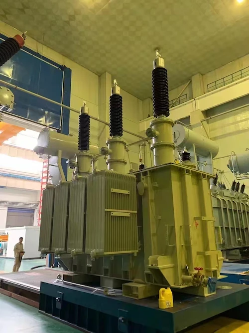
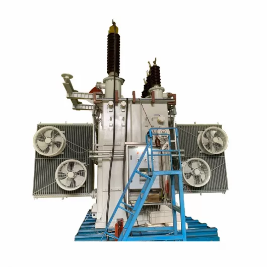
Quantity:1
Type:Oil-Filled, Outdoor, Station Type, Power Transformer
Continuous Rating:33 / 44 / 55 MVA
Cooling Class: ONAN/ONAF1/ONAF2
Temperature Rise: 65°
HV Winding: 138 kV Gnd Wye
LV Winding: 34.5 kV Gnd Wye
Tertiary:13.8 kV Buried Delta
Frequency: 60Hz
Winding Material HV/LV: Copper/Copper
Coil Construction: Detailed Description By Vendor
Impedance, at ONAN Rating: 8%
Core Construction: Core
HV Bushings Location: Top Cover
Oil Preservation System: Nitrogen Blanket
Quantity:1
Type:Oil-Filled, Outdoor, Station Type, Power Transformer
Continuous Rating:33 / 44 / 55 MVA
Cooling Class: ONAN/ONAF1/ONAF2
Temperature Rise: 65°
HV Winding: 138 kV
LV Winding: 34.5 kV
Tertiary:13.8 kV
Frequency: 60Hz
Winding Material HV/LV: Copper/Copper
Coil Construction: Detailed Description By Vendor
Impedance, at ONAN Rating: 9%
Tap Changer: 5 positions De-energized
HV Bushings Location: Top Cover
Oil Preservation System: Nitrogen Blanket
A power plant transformer is a device used for generating electrical power from one voltage level to another. It does this process while maintaining the same frequency but usually different voltage levels.
A transformer uses electromagnetic induction as a mechanism and transforms the voltage. Power plants employ power station transformers of various types, sizes, and ratings. This article by Daelim will be discussing everything to know about power plant transformers.
Daelim, a transformer manufacturer with over 15 years of field expertise, builds quality products that are both effective and cost-efficient. For example, their Daelim Belefic brand rose as the benchmark for high-performance transformers in China since 2005. Besides, they offer an extensive product line to satisfy any customer’s need at competitive prices. Also, Daelim strives to be environmentally friendly by using RoHS-compliant components whenever possible.
A power station transformer is a device that converts electricity from one voltage to another without altering its frequency. The transformer operates on an AC supply and uses mutual induction to convert voltages. You can find power plant transformers at power plants and are vital in running these facilities.
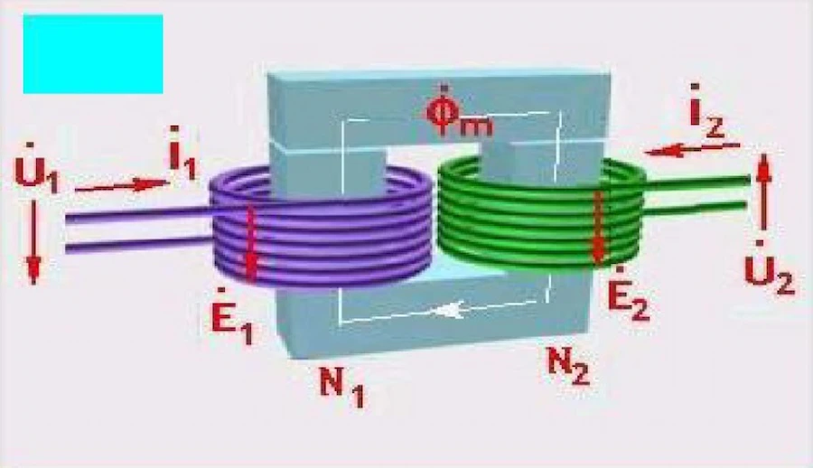
Power plant transformers are made up of primary and secondary coils joined to form a closed magnetic circuit. The system transfers energy from the primary coil’s electrical voltage level into the magnetic field within the transformer’s coils. Then these coils induce a current within its opposite polarity onto the secondary coil.
Energy suppliers use power plant transformers in industrial settings. They should have an alternating current applied to one of their windings, creating either an increase or decrease in voltage. Further features come with different numbers of windings, depending on their applications. Professionals often employ two-winding (with three wires) power plant transformers when using them for transmission purposes.
The transformer core works to direct the trail of magnetic flux; this prevents wasted energy. Once magnetized by a moving coil and allowed into an iron-core secondary coil without resistance, electrons move through it via electromotive force (EMF).
Now, the key behind transforming power is to pass electricity through wire coils near a conductor to create induction. This principle makes the current flow back and forth across their spaces at high speeds every time new voltage changes direction. This occurrence causes them to push against each other like magnets, so they don’t pull apart.
Besides, the two coils of wire cause alternating currents to flow through each other in different directions. This process is what defines a power station transformer. Transformers are made up of many layers that have been wound together to perform the job of conversion. Power can enter and exit at various points on the windings or “turns.” The energy lost due to heat produced in this process must be dissipated using fans since magnets cannot lose temperature.
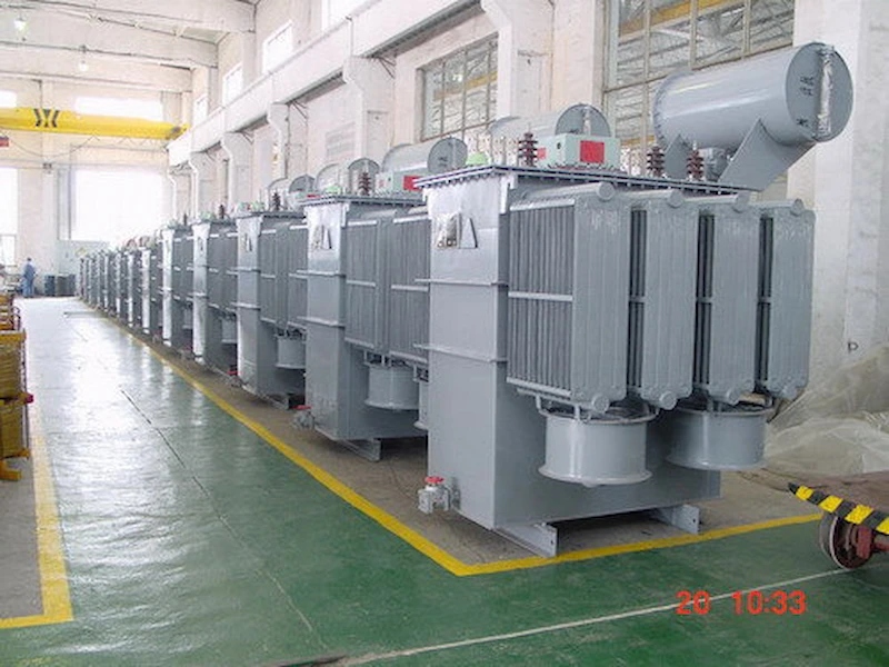
Power plant transformers (also called power transformers) are important units in an electric power generating station. They play a key role in transmitting electric power generated by generators and sending it to distribution systems.
A manufacturer can design power plant transformers for any ratings to meet specific needs, but these are the most common:
More so, power rating refers to the maximum electric current (I) that a transformer can carry under normal conditions. Various organizations like IEEE, IEC, or ANSI regulate the standard requirements such as ratings.
Power ratings may vary depending upon the temperature ranges within an operation. These ratings may also be because of insulation limitations and other factors. Therefore, it is advisable to use power ratings provided by the manufacturer rather than relying on universal values.
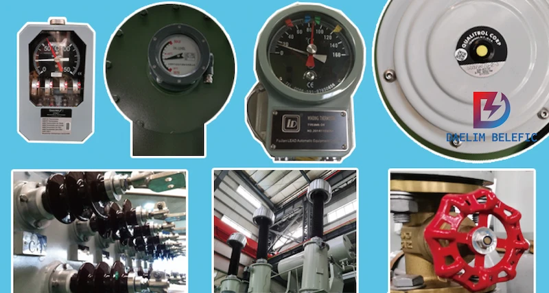
There are a variety of features to take note of for power plant transformers. These respective features can directly influence how your machine would fit into your application. Below are the checklists of features power plant transformers have:
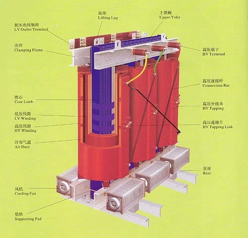
Transformer cores are the definitive identity of a transformer, and they dictate performance. They do so by converting voltage, which is done in conversion within it through Faraday’s law of induction. Power plant transformer cores can either be air-insulated or oil-insulated. Also, these transformers are typically made of silicon steel. This choice is due to their good magnetic conductivity and is very malleable with low cost per volume.

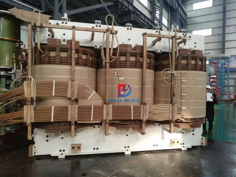
Transformers have two coils: one for the input and another to distribute power at a different voltage. The primary coil draws energy from an external source, whereas the secondary coil delivers this power with reduced volts.
What’s more, transformers consist of only two wires – but they’re very important. This is because transformers convert alternating current (AC) or household electricity running through them. This conversion allows you to use them for other appliances like lamps or TV sets that require direct current (DC). Power plant transformers can carry extreme amounts of current but often provide a specific amount based on the size.
The cooling design is an integral part of every power plant transformer. Inefficient cooling may lead to overheating, which can then cause performance inefficiencies. Thus, manufacturers design power plant transformers to operate over a wide range of ambient temperatures. The two prevailing cooling designs in the market are dry or air-cooled and oil-filled cooling.
An oil-cooled transformer will have an oil reservoir in which the transformer’s coils are immersed. Meanwhile, a dry-type transformer has no cooling fluids and often uses forced air to dissipate the heat. Power plant transformers are designed to keep their temperature within specified levels under extreme ambient conditions.
A manufacturer can make their transformer designs in a variety of ways. However, there are still common factors for every production. Below are other features that you might expect your power plant transformers to have:
The power networks are dominated by two types of transformers, which are power transformers and distribution transformers.
Power plant transformers are typically step-up transformers. They convert generated electricity to higher voltages to make long-distance distribution possible. The power is distributed through power station transformer lines to substations where they transform electricity into lower voltages for consumption.
Energy providers also use power station transformers in transmission grids. They are integral to high voltage direct current (HVDC) power transmission between generating plants and load centers. The power at these locations can be very high. Thus, for reliability, it is common to use two power transformers instead of one.
In addition, a two-unit configuration allows one transformer to transfer energy while its partner undergoes maintenance or repair. Also, this will enable operations to continue on a cyclical basis with a limited duration. ASEA/ABB developed this type of configuration in the 1960s and has been widely adopted since then.
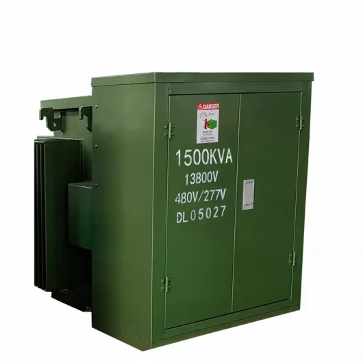
Meanwhile, distribution transformers are the end gateway before households can utilize electricity. Energy providers use distribution transformers to distribute electricity at low voltage. Typically 33kV is for industrial purposes and 440V-220V for domestic purposes. It works at low efficiency at 50-70%, is small, and is easy to install. Additionally, it has low magnetic losses and is not always fully loaded.
The distribution transformer’s primary function is to step down or change the voltage level from the transmission line.
Its secondary function is the electricity distribution to commercial areas, homes, and businesses requiring electricity under 13000 volts. They operate on 60Hz frequency and are normally distributed by distribution utility companies. The distribution lines that serve residential neighborhoods are usually buried underground or supported above ground.
You can categorize power plant transformers in a variety of ways. These classifications can include the function, build, or phase designs. Yet, it is also safe to note that overlapping categories is likely. It is common for manufacturers to employ multiple features in a design. Below are a few of the typing categories a power plant transformer may fall into.
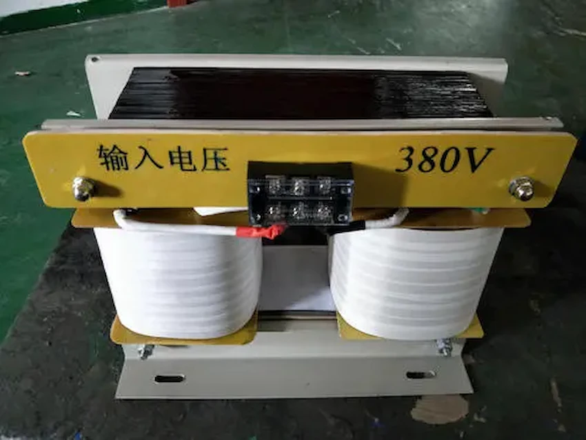
Transformer Three-Phase Dual Power Supply Automatic Switching Circuit Diagram
Energy providers use single-phase transformers to distribute power to rural areas, industrial parks, or communities with only one power feed. It has two hot terminals and one neutral terminal. Only a single input and output coil are necessary for its function.
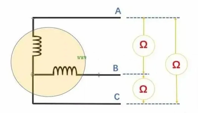
You can divide power plant transformers into single-phase and three-phase systems. In general, these types have lower rating thresholds due to limitations in cooling and performance efficiency.
Meanwhile, three-phase power is an alternating current with three different phases in a system. The three power feeds carry equal power but are 120 degrees apart in voltage and current flow. This configuration enables users to connect multiple loads across the phases to supply power to them. Professionals refer to these core designs as “delta” or “wye” configurations.
The most common type of transformer within a power plant is the three-phase. Three-phase systems are more efficient and are capable of handling higher ratings. They can also power three-phase motors, power tools and have the capacity to power large businesses. More so, their system configuration fits longer distances of power distribution.
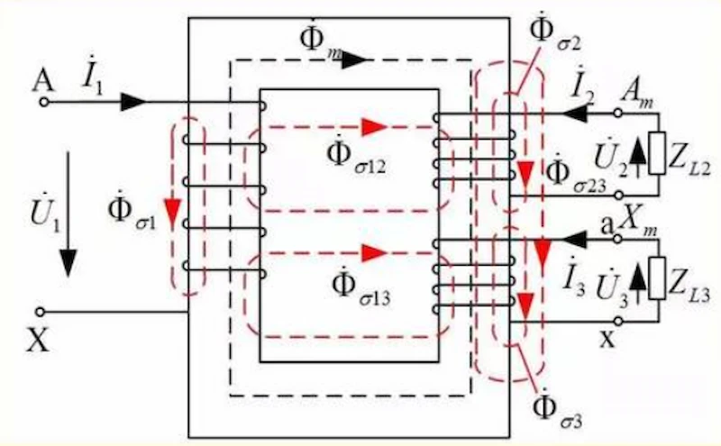
A two-winding transformer is a must when transmitting high voltage and low voltage from one power line to the other. The ratio of input to output should generally be greater than two. Additionally, professionals use two-winding transformers in situations where the electrical transmission requires different voltage output levels. These types of transformers come in all shapes and sizes.
Meanwhile, an autotransformer is necessary for conversions with less than two input to output ratios. These are comparatively lower conversion requirements than two winding transformers.
As the name suggests, this is a categorization based on the prescribed installation location. Not all units can be compatible for both locations. Certain features like cooling design affect this factor for storing. Other factors which can determine the appropriate storage areas also include noise pollution and mounting structure.
As aforementioned, the cooling design of your transformer can greatly influence the storage or mounting location.
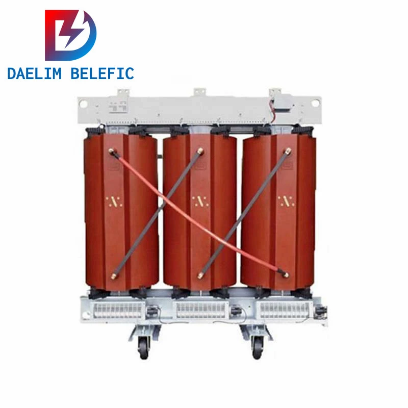
Dry-type transformers use natural ventilation for cooling. They are the most suitable transformer types indoors as they do not possess flammable fluids like their oil-filled counterparts. They use a resin-based system to ward off contaminants and keep their temperatures maintained. Lower rating transformers normally possess this type of cooling.
Some systems fit dry-type units with oil tanks for better performance. These transformers suit both indoor and outdoor installations. They are liquid-cooled dry-type transformers, also known as dry-and-liquid types or hybrids.
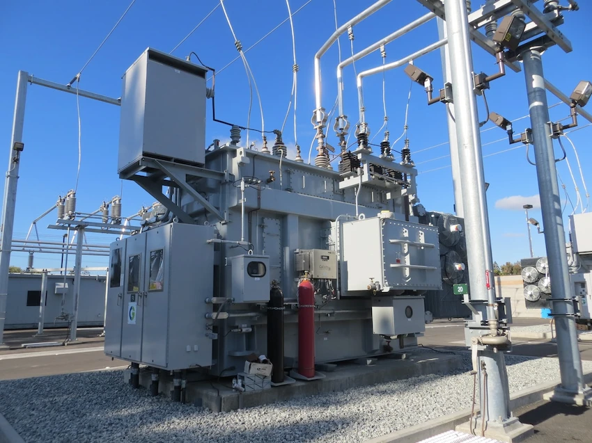
These units use flammable liquids like mineral or transformer oils. Therefore they are mostly suitable for outdoor installation. They need a large metal tank for storing the oil, which means more weight and higher installation cost than dry-types. These factors make them less popular than the dry types or dry & liquid types. Due to flammable fluids, these units require regular maintenance and inspection to ensure efficiency and safety.
Typically, these transformers will require a separate shelter or space far from densely populated buildings or locations. Still, they are capable of handling higher loads due to the advantages of oil cooling. At the same time, the other advantages like longer lifespan, ease of maintenance, and recyclability are where this type excels at.
Power plant transformers, as their name suggests, are primarily designated on power plants or substations. These are high voltage (115kV & above) units that handle larger electrical loads. Power companies employ power transformers for the transmission and distribution of electrical energy. They use the principle of primary and secondary coils to transfer large power loads without using excessive voltages.
A power station transformer is an essential component in modern industrial plants as well as traditional electric utility companies. They provide backup support during emergencies or when a load increases suddenly, for example, peak hours. Additionally, they also protect substation equipment from overloads and short circuits.
Power transformers offer safe protection for equipment, personnel, and adjacent lines. They also have applications ranging from nuclear fission plants to thermal power stations to solar system installations at homes.
The transformer equation is Vs/Vp = Ns/Np. This formula simply represents the ratio of primary to secondary voltages with the ratio of loop counts in their coils.
Transformers are a power electronic component that is used in power transmission and power distribution systems. They are made up to step down voltage levels as required, either for power transmission or distribution. Power transformers transfer power from one circuit to another with different voltage requirements and impedance characteristics.
Transformers are technically a requirement to make electricity usable for daily everyday needs. Without transformers, electricity is not transformable to a functional form of energy.
The concept behind transformers is to transform the alternating current from one voltage level to a level required by a device. Without transformers, electricity would only be able to go between low-currents and high-currents. For example, your house’s power circuit provides about 107 volts of AC down to as needed to run appliances. Transformers allow us to use devices that require lower voltages. Such as 12 V for electronics, 1.2 kV for electric railway tracks, or 106 kV for nuclear plants.
Stationary transformers or station transformers are transformers placed in an electric substation or power plant to transform voltage levels.
A transformer transfers electrical energy between two or more circuits by electromagnetic induction. A stationary transformer, as the name suggests, is used at one location and does not move. Stationary transformers are found in substations with no rotating transformers in use. But, they can also be found near generators inside power plants. They are what supply secondary voltages for starting up generators when needed.
A transformer cannot convert AC to DC or vice versa. AC to DC conversion works under a different electrical principle which is beyond the scope of transformer functions. Transformer works under the Induction Principle or Faraday’s Law.
Meanwhile, AC to DC conversion requires a completely different device called a rectifier. A rectifier converts AC to DC by tapping off the current at certain points along with the wave. It uses a filter to transform it back into a pure sine wave. This filtering is very significant because it helps ensure that no lines are affected during this process.
A transformer cannot work on direct current. A transformer works to transform alternating current into a different alternating current. It may work on a direct voltage, but this is not the same as a direct current.
You will see transformers used in many places where cables and wires bring electricity from one location to another. Transformers are used to increase or decrease voltage levels along those lines. For example, you can use transformers at distribution-level power plants near transmission-level substations.
Transformers can also go right at the end of a power line. They are prevalent in substations for level shifting between high and low voltages—all working under an alternating current.
A power plant transformer is undoubtedly a valuable component in electrical power distribution. The need for an efficient and top-performing machine and picking the correct transformer specifications is just as crucial as its reliability. So, you can only expect it from tested brands in the industry.
Daelim created Daelim Belefic, the leading brand of transformers in China. Daelim’s extensive field expertise and background allow them to deliver satisfactory products for the market. If looking for quality power plant transformers or other electrical solutions, look no further; Daelim has it.
Daelim believes it is important to make great products and produce these items at affordable rates. They never compromise on performance or environmental responsibility within each component. This commitment makes them your one-stop shop for all things electrical.
Contact us today for further inquiries or partnerships.
When you need to find more than just existing transformers, Daelim’s Transformer Service Center can help you design and produce distribution transformers that meet your unique needs.
We have our own factory and a professional team of engineers, which can design and modify application requirements that meet all your conditions.
Download Resource
ELECTRIC, WITH AN ENGE-- DAELIM BELEFIC
After filling in the contact information, you can download the PDF.