ELECTRIC, WITH AN EDGE
This article explains in detail the structure of oil immersed transformer, the difference between oil immersed transformer and dry-type transformer, oil-immersed transformer specification, common faults of oil-immersed transformer and its solutions.
As a transformer manufacturer that has passed IEEE, CSA, ANSI and other standards, Daelim has more than 16 years of experience in the production and design of oil immersed transformers.
Can help you order transformers quickly and provide you with the most efficient solution.
Oil Immersed produced by Daelim has been recognized by the majority of users for its low energy consumption and high efficiency.
They are widely used in Canada, the United States and other countries.
A professional installation team can arrive at your place of use to provide you with professional services.
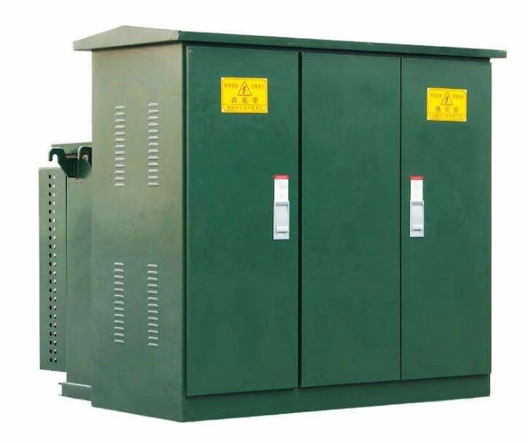
High Voltage Distribution Transformer
-A lot of electrical companies use high voltage Distribution transformer to effectively operate at applications that are at high voltage levels.
Electric Pole Transformer | Single Phase Transformer
-Learn the fundamentals of Electric Pole Transformers, including What is pole mounted distribution transformer, pole mounted transformer specifications, pole mounted transformer drawing, pole mounted transformer sizes and custom options.
Power Transformer: The Ultimate FAQ Guide
-Power transformers are widely used by companies, industries, and businesses nowadays but what is it for? And should you consider getting one?
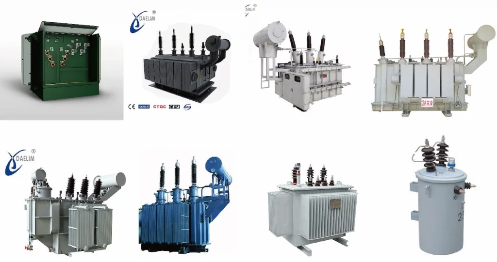
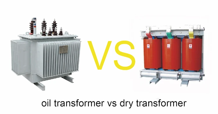
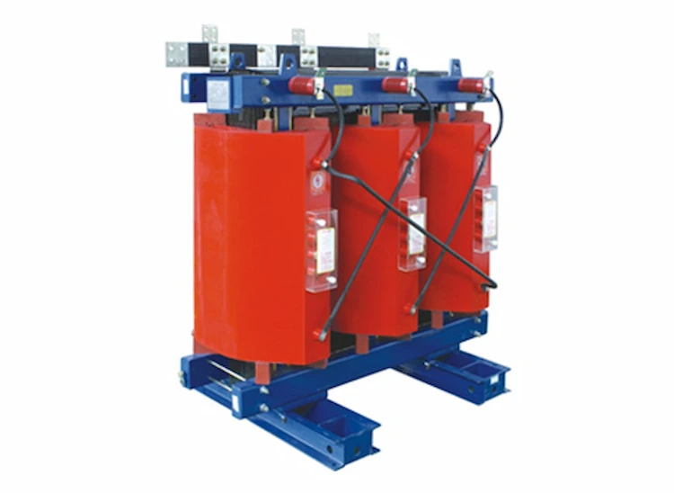
There are many types of transformers currently used, mainly oil-immersed and dry-type transformers.
No matter what kind of transformer, its internal basic structure and working principle are the same.
The oil-immersed transformer is to change the voltage level, use the principle of electromagnetic induction, and control the number of turns of the transformer to achieve the rise and fall of the voltage, in preparation for further transmission and use of electric energy.
Generally, the main transformer of the booster station is oil-immersed, with a transformation ratio of 20KV/500KV, or 20KV/220KV.
Generally, power plants are used to drive power plants with their own loads (such as coal mills, induced draft fans, air supply fans, circulating water pumps, etc.).
The factory transformer is also an oil-immersed transformer, and its transformation ratio is 20KV/6KV.
Oil-immersed transformers are widely used in the current power industry, and their operating conditions are directly related to the quality of power supply.
There is an iron core in the oil immersed transformer, and two mutually insulated windings are wound around the iron core.
Among them, the side connected to the power supply is called the primary winding, and the side that outputs electrical energy is called the secondary winding.
When the AC power supply voltage is applied to the primary side winding, an AC current flows through the winding, and an alternating magnetic flux is generated in the iron core.
This alternating magnetic flux not only passes through the primary winding, but also passes through the secondary winding, and induced potentials E1 and E2 are generated in the two windings respectively.
The ratio of the induced electromotive force on the primary and secondary sides of the transformer is equal to the ratio of the turns of the primary and secondary side windings.
Therefore, when the number of turns of the primary and secondary windings of the transformer is different, the voltage can be transformed.
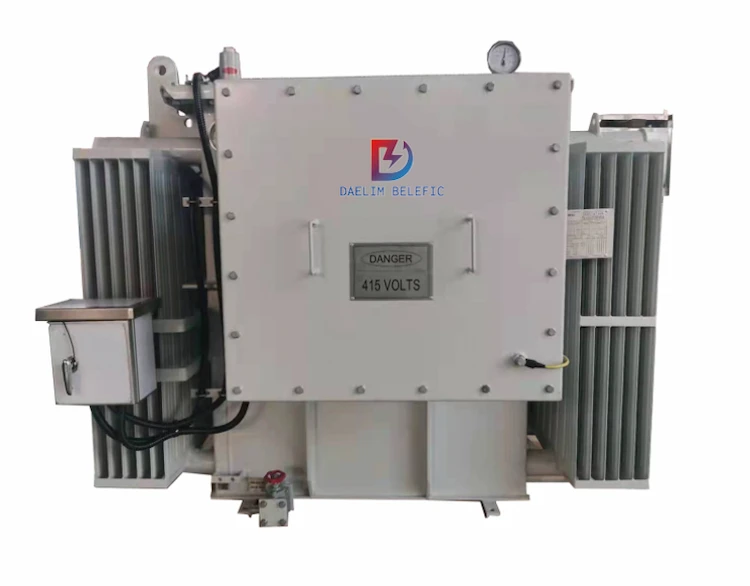
Compared with ordinary transformers, the cooling method is slightly different.
During the operation of oil-immersed power transformers, the heat of the windings and iron cores is first transferred to the oil, and then to the cooling medium through the oil.
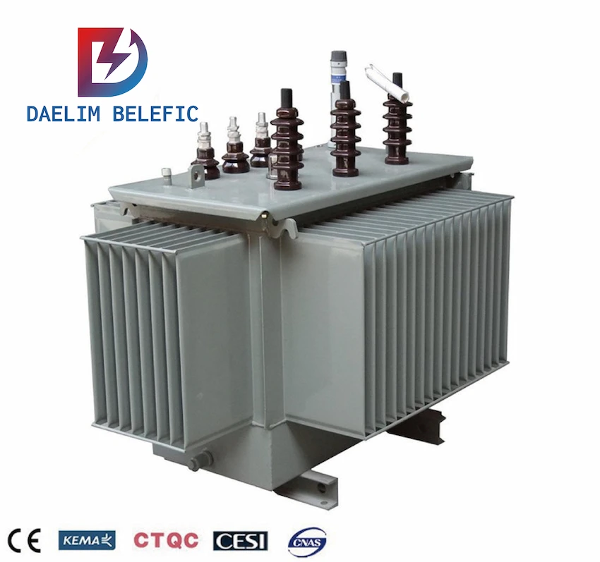
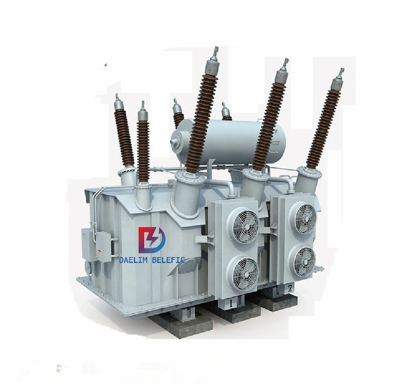
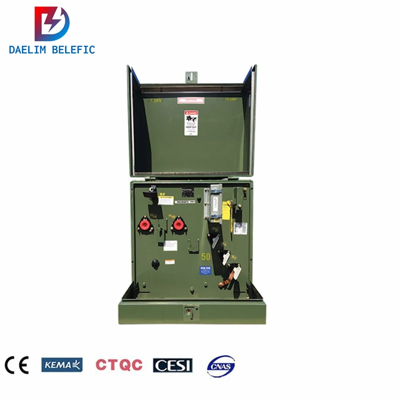
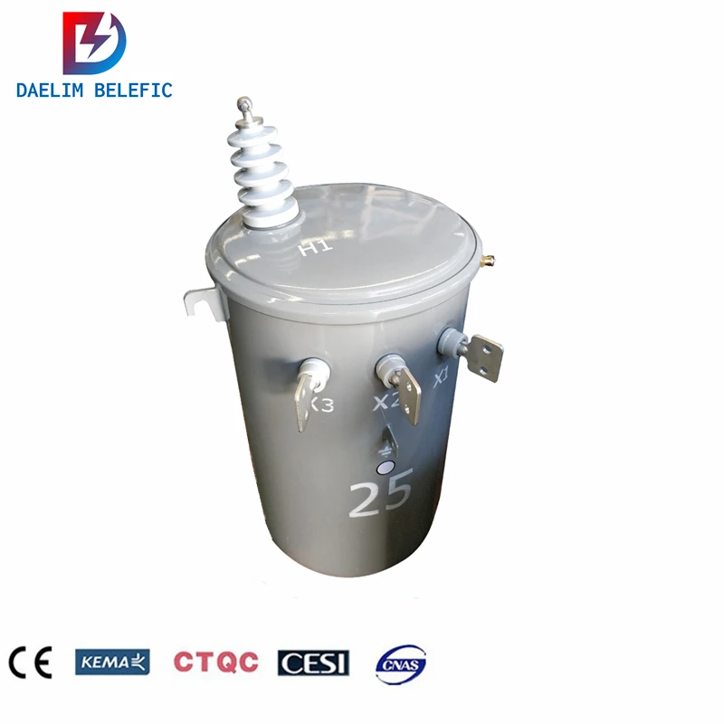
The models of oil-immersed transformers are from left to right:
Oil immersed transformers have a wide range of applications, both indoors and outdoors.
The main features of oil-immersed transformers are as follows:
(1) Most of the oil immersed transformers use cylindrical structure windings.
Except for small-capacity transformers, most of them are made of copper wire, and the pie structure is mainly used for high-voltage windings.
This structure can balance the ampere-turns distribution of the windings in the transformer to a certain extent, reduce the leakage magnetic flux, improve the mechanical strength, and also improve the short-circuit resistance.
(2) The iron core and windings should be reinforced and tightened.
Since the transformer has to withstand possible short-circuit faults in the power system and vibration during transportation, the body of the transformer must be fastened.
(3) The fuel tank adopts the structure of barrel type and bell type.
It is necessary to avoid the infiltration of oxygen, moisture and other substances, effectively isolate the contact between the transformer and the external environment, and play a sealing role.
It is also necessary to meet the influence of oil volume changes due to temperature changes and sufficient mechanical strength.
After the oil immersed transformer runs for a period of time, during the operation, due to many external effects such as electric field, humidity, temperature and mechanical force, the aging of the transformer insulator will be accelerated.
At present, the degree of polymerization of oil immersed transformer insulating materials is the most important basis for judging the aging degree of transformer insulation.
In practical work, the average degree of polymerization of insulating paperboard is mainly used to judge the aging degree of Oil immersed transformers.
At present, we use the following standards:
When a short circuit occurs on the outside of the Oil-immersed transformer, the tensile strength of the insulating paper will decrease to 60% of the initial value;
The danger level refers to the reduction of the maximum tensile strength of the Oil immersed transformer to 15% of the initial value.
That is, n L/n0 = ( 1 – r) L, where n0 is the average DP starting value;
n L is the mean DP after L; L is the number of years, a; r is the mean DP decline rate.
Large-scale power transformers generally use oil-paper insulation structure, while solid insulation has irreversible aging characteristics, and its performance status has a decisive impact on the operating life and maintenance strategy of the transformer.
Under the influence of physical aging, mechanical equipment and mechanical parts will experience obvious mechanical failures.
According to the use and maintenance characteristics of mechanical equipment, summarizing the basic laws of mechanical failures, analyzing the basic characteristics of mechanical failures, is conducive to the correct choice of maintenance methods for mechanical equipment.
At present, oil-paper insulation structures have been widely used in the design and production of large power transformers.
During operation, it has been subjected to electrical, thermal, mechanical and chemical stresses, and its performance is continuously degraded, which may easily lead to unplanned power outages or even catastrophic accidents.
Insulating oil can improve its insulating properties by filtering or replacing the transformer during its service, and the transformer cardboard has irreversible aging characteristics.
Therefore, the life of the transformer largely depends on the electrical and mechanical properties of solid insulating materials such as insulating cardboard.
The insulation of the transformer is mainly made of oil paper, that is, the insulating paper is impregnated with insulating oil, so that the air gap between the fibers of the insulating paper can be eliminated, and the electrical strength of the insulation can be effectively improved.
Power transformer insulation paper is often used for power cable paper, high-voltage cable paper and transformer turn insulation paper, insulation of transformers and other electrical products; high-voltage cable paper is generally used for 110 ~ 330kV transformer and transformer insulation;
Transformer turn insulating paper is a better electrical insulating paper for 500kV transformers, transformers and reactors.
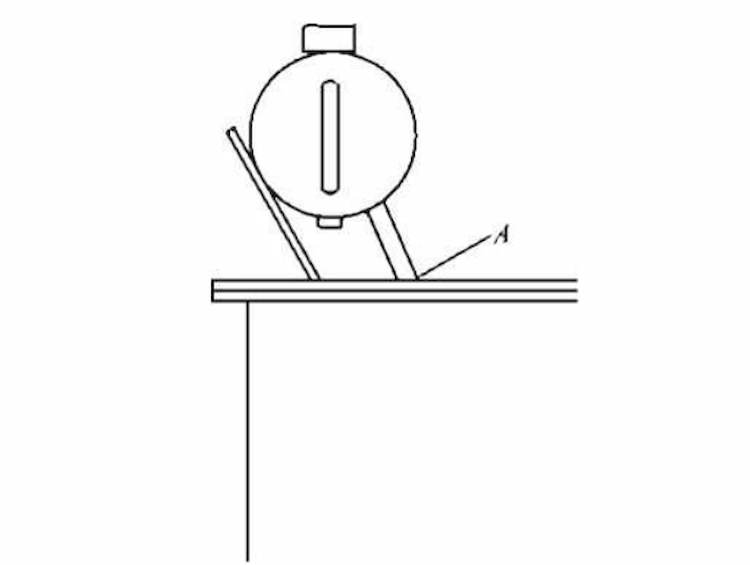
The oil conservator bracket of the oil-immersed transformer is mostly bent from flat steel.
During installation and transportation, the height and position of the oil conservator are suitable for the operation and movement of the entire transformer.
Therefore, it is easy to cause the flange from the oil conservator to the oil tank cover to be overstressed, as shown at A in the figure, the oil leaks due to the cracked weld.
And because such small transformers are often installed on the bench, when other installations are carried out, they are stepped on the oil conservator, which will also cause oil leakage from the connecting pipes and flanges.
During the operation of the oil-immersed transformer, the electric field and the magnetic field continue to stagger for a long time, interfering with each other, and the accumulation of quantity produces a qualitative leap, that is, the continuous accumulation of internal performance will lead to the failure of the transformer.
The faults of oil-immersed transformers are mainly divided into thermal faults and electrical faults.
There are many types of common faults, including internal faults and external faults, which are listed in Table 1.
| Fault type | Fault phenomenon |
Thermal Failure | Winding temperature rise is too high |
| Magnetic leakage causes overheating | |
| Poor grounding of the iron core causes overheating | |
| Overheating due to blockage of oil passages inside windings | |
| Overheating due to poor contact at lead connections | |
| Overheating caused by poor contact between the dynamic and static contacts of the decomposition switch | |
| Electrical Failure | Oil gap discharge in insulation |
| Winding short circuit to ground or phase to phase | |
| Bare metal discharge due to insulation rupture | |
| Insulation aging leads to discharge between windings | |
| Discharge at lead connections due to poor contact | |
| Discharge to ground due to poor grounding of each grounding part | |
| Discharge due to uneven distribution of electric field due to design |
The fault diagnosis method of oil-immersed transformer is to analyze the acquired fault information of the transformer, and judge the fault type of the transformer with the result of the data analysis.
In this process, the accuracy of the collected information plays a crucial role in the accuracy of fault diagnosis.
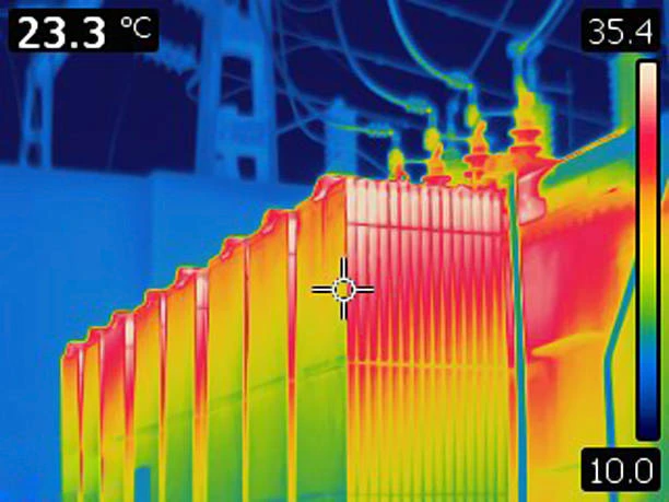
There are six types of diagnostic methods for transformer status in actual engineering: oil chromatography analysis method, partial discharge method, infrared temperature measurement method, electrical test method, oil chemical test method and winding deformation test method.
The most basic method proposed by Algorithms is oil chromatography, which is an effective method for judging transformer faults.
The rest of the methods are based on oil chromatography to expand analysis and research.
Check whether the transformer is disconnected, soldered, and desoldered, and whether the insulating material is burnt or damaged. Whether there is burnt smell or smoke after power-on;
Use a multimeter to check the continuity of the winding. To check whether the winding is short-circuited, a light bulb can be connected in series with the winding. Its voltage and power are determined according to the voltage capacity of the power transformer. No circuit breaker;
Use a megohmmeter to test the insulation resistance between the windings, between the windings and the iron core, and between the windings and the casing, and the value should be above 1M;
Connect the rated voltage to the primary winding of the Oil-immersed transformer, measure the no-load voltage on the secondary side, the general error is between ±(3%~5%)”;
The oil-immersed transformer is connected to a fixed load.
When energized for 1h, the temperature should not exceed the allowable temperature of the insulating material of the transformer.
The increase in temperature will cause the insulation to age, affect the service life of the transformer, or even extinguish
The oil temperature of the oil-immersed transformer will continue to rise under normal operation and cooling. The main reasons are as follows.
(1) Damaged eddy currents or the insulation of the core bolts for clamping the iron core can cause the oil temperature of the oil-immersed transformer to rise, and the eddy currents will make the iron core overheated for a long time.
In turn, the silicon steel sheet is damaged, resulting in a short circuit between the silicon steel sheet and the core bolt.
At this time, a large current will pass through the core bolt, which will cause the bolt to heat up, and eventually cause the oil temperature of the oil-immersed transformer to rise.
(2) There are large resistance short circuits on the secondary line, local interlayer and inter-turn short circuits of the windings, problems with internal contacts, and increased contact resistance, etc., which can increase the oil temperature of the transformer.
(3) The radiator valve is not opened in time, the oil is insufficient, the load is too large, the ambient temperature is too high, the oil pump and the cooling fan are faulty, etc.
In view of the phenomenon that the oil temperature of the oil-immersed transformer is too high, generally the oil level will drop significantly if the oil temperature is too high.
If the oil level is lowered due to excessive oil leakage, the gas protection should be immediately changed to only act on the signal, and effective measures should be taken to improve the current situation of oil leakage and replenish the oil in time.
Internal failure of oil immersed transformers and overheating of components can change the original smell and color.
(1) Discoloration and abnormal odor are generally caused by the loosening of the fastening part of the secondary sleeve terminal and the high temperature of the contact surface;
(2) The phenomenon of paint discoloration caused by local heating of the fuel tank is often closely related to the magnetic flux leakage effect of the transformer;
(3) The damaged porcelain casing will cause the cooling fan and oil pump to burn and emit a burning smell;
(4) The discoloration of the hygrometer is related to the excessive amount of water infiltrating the oil chamber, damage to the gasket, and excessive moisture absorption;
(5) The flash point of oil containing carbon particles and moisture will generally decrease, the acid value will increase, and the insulation performance needs to be improved, which is likely to cause breakdown of the winding and the casing.
The phenomenon of oil leakage during the operation of oil immersed transformer is relatively common, and the main reasons are as follows.
(1) The interface between the fuel tank and the parts is not well sealed, the castings and weldments are insufficient, the operating load is too large, and there is a shock phenomenon.
(2) The internal failure of the Oil-immersed transformer will cause the oil temperature to rise, making the oil volume larger, and causing oil injection or oil leakage.
The quality of the oil can be judged by observing the specific shape and color of the oil.
Judge whether the oil level is normal according to the ambient temperature standard line.
If the oil level is too low, the transformer will leak oil.
If the oil level is too high, the internal cooling device may be faulty.
Iron core fault is a relatively common fault in oil-immersed transformers. Mainly for the following two.
When this fault occurs, the iron core is partially overheated, characteristic gas appears and there is intermittent discharge inside the transformer.
The failure is mainly caused by the following factors:
(1) The iron core laminations are not fastened or the tightening bolts are twisted skewed, resulting in partial short-circuit and overheating of the iron core.
For this fault, it is necessary to loosen the clamps to straighten out the laminations at the loose places and then tighten them.
Align the fastening bolts, add insulating sleeves and insulating pads, and then tighten the nuts.
(2) The nut on the through-center screw is loose, and the laminations at the upper and lower ends of the yoke and side column are concave.
For this fault, it is necessary to remove the through-core screw and clamp, take out the winding, and conduct a comprehensive inspection of the iron core.
(3) The lamination burr is large, causing a partial short circuit of the lamination to generate eddy current, causing local overheating of the iron core.
This fault has a cutting feel on the laminated surface, and the burr is obviously exceeding the standard. The micrometer is used to measure the range of 0.08~0.13mm. It needs to be deburred and painted and dried.
When the fault occurs, it mainly shows that the paint film or oxide film on the surface of some iron core laminations falls off. After chromatographic analysis, it is found that the gas is CH4, H2, C2H4 and exceeds the standard.
The failure is mainly caused by the following reasons:
(1) The insulation of the threaded rod is broken or overheated and carbonized, the seat sleeve of the threaded rod is too long, and the seat sleeve collides with the iron core. Such failures require replacement of cracked or carbonized feedthrough insulation.
(2) Improper clamping position of the iron clamps will touch the iron core, resulting in partial short circuit and overheating of the iron core. For this kind of failure, it is necessary to loosen the iron clamp and adjust the position before tightening the nut.
(3) Due to carelessness in the final assembly of the transformer, other foreign objects such as welding slag and electrode tips fall on the iron core, causing a partial short circuit of the iron core. For such failures, staff should be arranged to remove the welding slag and metal falling into the iron core. foreign body.
(4) Install the grounding copper sheet. The copper sheet is too long.
After the connection, the copper sheet touches another part of the iron core lamination, forming two or more points of grounding and short circuit, which makes the iron core partially overheated.
For such faults, it is necessary to take out the ground copper sheet, cut off the excess length, and then insert it into the lamination to fix it firmly.
After an oil-immersed transformer is delivered or repaired, three tests are usually required: insulation resistance measurement, no-load voltage test and no-load current test.
Use a megohmmeter to measure the insulation resistance between the windings and the winding to the iron core, and the value should be greater than 1MQ;
When the primary side input voltage (AC220V), the allowable error of the secondary side no-load voltage is less than 10%;
When the primary side input voltage (AC220V), the no-load current should be 5%~8% of the rated current value. If the no-load current exceeds 10% of the rated value, the loss will be large; if the no-load current exceeds 20% of the rated value, the transformer will heat up seriously and cannot be used.
In order to ensure the safety and stability of electrical engineering and construction projects, many transformer manufacturers have begun to increase the R&D and design of dry-type and oil-immersed transformer equipment, which are increasingly widely used in electrical facilities.
However, dry-type and oil-immersed transformers have their own advantages and disadvantages.
Dry-type transformers are very easy to maintain and maintain, and their fire resistance is also very good, making them very safe to use.
However, compared with traditional dry-type transformers, oil-immersed transformers have obvious advantages in no-load and load energy consumption.
In the power grid system, oil-immersed transformers have been widely used. The only fly in the ointment is that the insulating oil is easy to burn, and it is not conducive to low-carbon environmental protection requirements.
Dry-type transformers usually have the characteristics of oil-free, moisture-proof, heat insulation and dust resistance.
The discharge capacity of some areas of the dry-type transformer is not very high, and it is not suitable for combustion. It has good fire protection advantages, effectively preventing fire hazards, and reducing the capital investment and expenditure for fire prevention and disposal.
This kind of dry-type transformer has no oil leakage phenomenon, does not need to be repaired and maintained frequently, and also reduces the manpower input for frequent inspection and processing.
In addition, this dry-type transformer is equipped in houses and buildings. During the operation and construction, it adopts the method of no hanging core, which does not need to take up too much space, and also saves the project cost.
At present, it is very common in the electrical facilities of many civil air defense lower rooms and large-scale housing construction projects with strict fire resistance requirements such as multi-storey and high-rise buildings.
In particular, the epoxy resin dry-type transformers produced by daelim in recent years have better solved the insulation and heat resistance properties of the production materials, preventing premature aging and damage.
The fireproof grade of epoxy resin dry-type transformers produced by daelim has reached the H level, and it has been widely favored by many users.
Usually, when temperature detection is performed, it is mainly based on pre-set temperature sensing facilities.
The base point does not change frequently, the value of the general temperature does not change significantly, and even if the heat is concentrated in some parts, it cannot be accurately identified.
Therefore, there is a large error, and this insulating material cannot be restored to its original state once it is damaged.
When the old damage accumulates to a certain extent, if there is a safety hazard, the transformer cannot be repaired in time, and has to be scrapped in advance.
Once the epoxy resin is scrapped, it cannot be completely recycled, so the economic effect is usually not very good.
When the oil-immersed transformer is developed and designed, it mainly uses the heat dissipation function of the transformer oil. The structure type is not very complicated, the design and manufacture are very simple and applicable, and the operation is relatively safe and stable.
Therefore, in recent years, the application has become more and more extensive, and many electrical projects are equipped with this oil-immersed transformer equipment.
Since transformer oil is used for heat dissipation, the heat is especially transferred to the external metal structure.
Therefore, the heat dissipation is relatively balanced and fast, and the insulation effect can be restored quickly and in time.
However, this kind of transformer oil itself is very easy to burn, and there is a shortage of heat resistance, and the aging phenomenon is more prominent.
Therefore, the design of daelim fully considers the above-mentioned characteristics, strictly follows the relevant provisions of fire protection regulations, scientifically sets fire protection grade standards and equips oil fire extinguishing facilities during research and development and later construction and application.
Daelim has established professional installation teams in many countries. This installation team can properly handle the problem of increased oil flow in the event of a fire. For insulating oil that may be aged and qualitatively changed, testing facilities should be installed and regularly inspected and replaced to promote the recycling of oil.
In recent years, Daelim has continuously developed new oil-immersed transformers, and has designed and developed a number of patented technologies.
Daelim’s fully enclosed oil-immersed transformer equipment has been rapidly developed, designed and used. Through the performance of the oil’s own cold and heat regulation performance, the external air circulation is blocked and oil leakage is prevented.
Because the oil-immersed transformer does not use breathing facilities, it avoids the hidden danger of oxidation and increases the service life.
At the same time, the design and installation does not require too much space, and the energy consumption is relatively small. The energy consumption is reduced by more than 30% at no load, the current loss is reduced by 50%, and the noise is reduced by 8 decibels.
Therefore, it is only necessary to optimize technical measures in the design of oil-immersed transformers to overcome the adverse effects of oil burning, and oil-immersed transformers will obtain a wider space for use than dry-type transformers.
For oil-immersed transformers, the core components are the iron core and windings, which constitute the overall framework of the transformer.
Specifically, for conventional oil-immersed transformers, the body needs to be immersed in a closed tank filled with transformer oil.
At the same time, relying on the insulating sleeve, the connection between the winding and the external circuit is realized.
Oil immersed transformer high and low voltage bushings are the main insulating devices outside the transformer box.
Most oil immersed transformer bushings are made of ceramic on the outside with conductive rods in the middle.
The insulating bushing is installed on the top cover of the transformer oil tank. One end of the conductive rod is inside the oil tank, which is connected to the terminals of the high and low voltage windings of the oil immersed transformer respectively, and the one end outside the oil tank is connected to the external circuit.
The higher the winding voltage level, the larger the size of the insulating sleeve and the more complicated the structure.
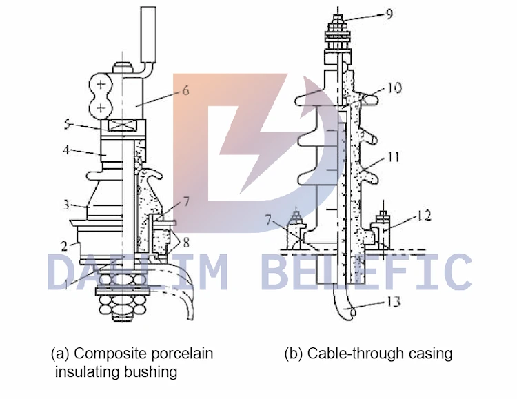
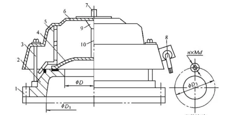
Figure (a) is a composite porcelain insulated bushing (BF type), its rated voltage is IkV and below, and the rated current is 300-4000AD. The bushing is composed of an upper porcelain sleeve and a lower porcelain sleeve to form an insulating part.
The upper porcelain sleeve serves as radial insulation and air side axial insulation, and the lower porcelain sleeve serves as oil side or air side axial insulation.
The conductive rod passes through the center of the porcelain sleeve, and the upper and lower porcelain sleeves are pressed on the box cover around the transformer installation hole by using the welding positioning piece at the lower end of the guide rod and the nut at the upper end.
The conductive rod is used to connect the lead wire. When the current of the lead wire at the tail of the bushing is 1000A and below, the single circuit is connected with a nut; when the rated current is 1200~4000A, the lead wire is connected into two circuits.
When the rated current is 600A and below, the connection of the external lead wire of the porcelain tube is directly connected with a nut; when the rated current is 800A and above, the lead wire is connected by a terminal, bolt, nut and external busbar.
The single-piece porcelain insulating sleeve is a guide rod type (BD type) and a cable-through type (BDL type). Figure (b) is a cable-through type structure. There is a porcelain sleeve. The clip is installed on the transformer box cover. There is a fixing groove on the upper part of the cable threaded sleeve, and a fixing groove on the lower part of the rod threaded sleeve, so as not to rotate when the lead wire is connected.
The grid voltage varies with the operating mode and the size of the load. The grid voltage is too high or too low, which directly affects the use of electrical equipment.
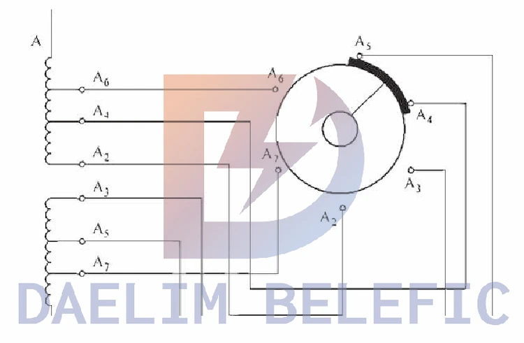
In order to ensure the rated output voltage of the transformer, the output voltage can be changed by changing the position of the tap tap of the primary coil, that is, changing the number of turns connected to the transformer coil.
In the three-phase coil on the primary side of the transformer, several taps are drawn according to the number of turns, and are connected to the tap changer according to a certain wiring method.
As shown in the figure. There is a contact that can be rotated in the center of the switch. When the voltage of the transformer needs to be adjusted, changing the position of the tap changer changes the transformation ratio of the transformer.
The radiator consists of heat pipes or fins mounted around the oil immersed transformer.
When the oil immersed transformer is running, when there is a temperature difference between the oil temperature of the upper layer and the oil temperature of the lower layer, the circulating convection of the oil is promoted through the radiator, so that the high temperature oil around the core of the oil immersed transformer is cooled by the radiator and then sent to the oil tank, which plays a The effect of reducing the operating temperature of the transformer.
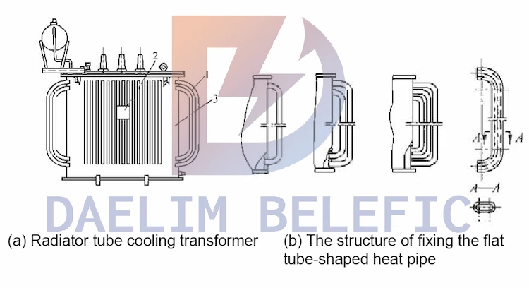
When the capacity of the oil immersed transformer is increased, the natural heat dissipation and cooling of the simple case cannot meet the requirements, and the heat dissipation pipe type should be used for heat dissipation, and many heat dissipation pipes are welded around the case, as shown in the figure.
The number of layers of the tube is generally 1 to 3 layers, and the flat tube flattened by the 040mm seamed steel tube is used as the heat dissipation pipe.
When the oil immersed transformer is running, the hot oil enters from the upper end of the cooling pipe, and the cold oil flows into the bottom of the transformer from the lower end of the pipe.
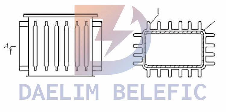
The corrugated fuel tank is welded with many corrugated grids on the outside of the tank wall of the fuel tank, and oil guide holes are opened on the corresponding tank wall of the convex part.
The corrugated grid is mainly used to dissipate heat and adjust the internal pressure of the transformer.
The corrugated grid is folded from a thin steel plate with a thickness of 1~2mm, each groove is more than ten millimeters wide, the spacing is 30~40mm, and the groove depth is 100~200mm.
One or more cooling fans can be installed in the removable radiator frame of large and medium oil immersed transformers, as shown.
When the hot oil circulates in the heat pipe, the fan blows the air to make the hot oil flowing in the pipe cool faster.
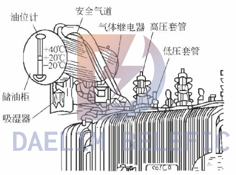
The explosion-proof pipe is also called the safety airway, which is located on the top cover of the transformer, as shown in the figure.
One end is connected with the box, the other end is sealed with an explosion-proof film (glass film or phenolic cardboard), and a small tube is connected to the upper part of the oil pillow.
The function of the explosion-proof pipe is that when a fault occurs in the transformer tank, the oil is decomposed to generate a large amount of gas, which causes the pressure in the tank to increase sharply. If the gas is not quickly removed, the tank may be damaged.
With the explosion-proof pipe, when the pressure in the fuel tank increases sharply to a certain value, a layer of glass film or phenolic cardboard at the outlet of the upper part of the pipe is broken, so that the oil flow can be ejected rapidly to protect the fuel tank from explosion.
The upper small tube is to ensure that the gas pressure in the upper space of the explosion-proof tube and the upper part of the oil pillow are balanced under normal operation conditions, so as to avoid the malfunction of the gas relay caused by the loose glass membrane, and at the same time to ensure the sealing of the glass membrane.
However, due to the high dispersion of the blasting pressure, the glass is easy to fall into the transformer after it is broken, and it is difficult to take it out, and it is difficult to seal when repairing. At present, the new transformers have adopted pressure relief valves instead of safety air passages.
The pressure relief valve is a safety protection valve, as an explosion-proof protection device for the fuel tank, it can cut off the power supply in time and avoid the deformation and bursting of the fuel tank.
The pressure relief valve has a metal diaphragm, which is normally pressed against the valve seat by the back pressure of the spring.
When the pressure of the oil tank rises above the spring pressure, the diaphragm will be lifted up, and the transformer oil will be sprayed out between the diaphragm and the valve seat, so that the internal pressure of the oil tank will decrease rapidly.
When the pressure drops to the closing pressure of the valve, the valve closes reliably, effectively preventing outside air, moisture and other impurities from entering the fuel tank. The action is more accurate and reliable than the safety airway, and no parts are damaged after the action, and no need to be replaced.
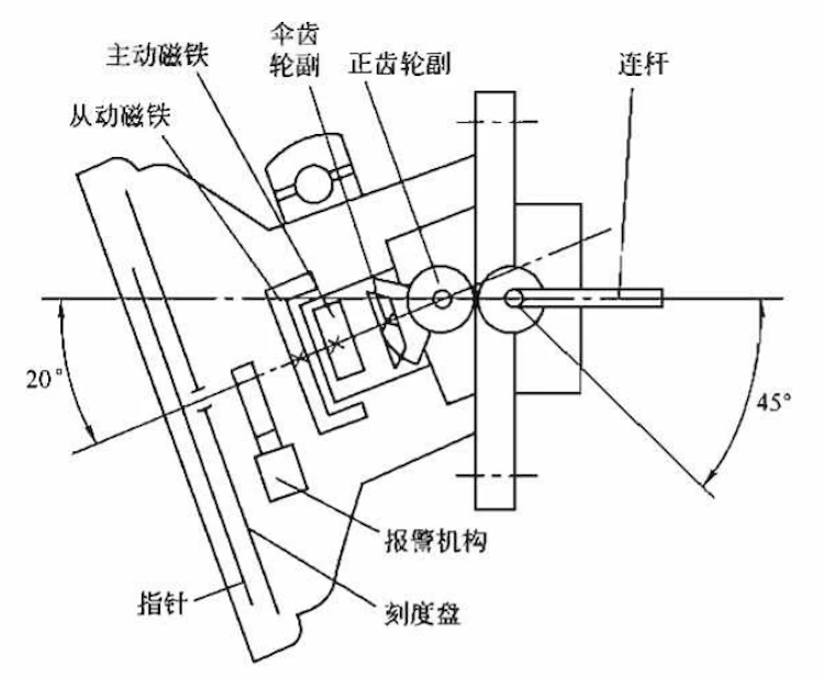
The fully sealed oil conservator generally adopts the pointer oil level gauge.
The pointer oil level gauge is also called the ferromagnetic oil level gauge. The basic structure is shown in the figure.
It is suitable for oil conservators of oil immersed transformers such as large diaphragm type, with alarms showing oil level and minimum and maximum limit oil levels.
The commonly used pointer oil level gauges are UZB type and UZF type oil level gauge, among which: U is an oil level gauge, Z is a pointer type, B is a transformer, and F is a floating ball type.
The pointer oil level gauge uses the oil conservator diaphragm or floating ball as the sensing element. The lower line displacement becomes the angular displacement of the connecting rod around the fixed axis, and then the pointer is rotated through a pair of magnets and other transmission mechanisms to indirectly display the oil level.
The table is equipped with a signal setting for the limit oil level, and a signal is sent when the oil level is too high or too low.
Transformer oil spilled from too high oil level will make the moisture absorber ineffective. The relay operates when the oil level is too low.
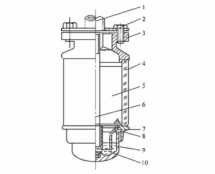
The moisture absorber is a small tank filled with moisture-absorbing substances.
When the air in the air chamber above the oil storage tank expands and contracts, the discharge of internal air or the inhalation of external air must be carried out through the moisture absorber.
The function of the moisture absorber is to absorb the moisture and impurities in the air when the oil in the oil pillow communicates with the atmosphere through it, so as to maintain the good performance of the insulating oil.
The structure of the dehumidifier is shown in Fig.
It is equipped with desiccant silica gel inside. The dry silica gel is blue and turns pink after absorbing moisture. It should be used again after replacement or drying.
The life of an oil immersed transformer depends on the operating temperature of the transformer.
During the operation of the transformer, the heat generated by the iron core and the winding changes the oil temperature of the transformer, and the thermometer is used to monitor the load condition of the transformer.
Thermometers include mercury thermometers, signal thermometers and resistance thermometers. Mercury thermometers are accurate but inconvenient to observe and are only suitable for small transformers.
Transformers above 1000kVA are equipped with signal thermometers (pressure thermometers).
Transformers of 8000kVA and above should also be equipped with a resistance thermometer (remote control thermometer).
Transformers of 40000kVA and above have a signal thermometer and a resistance thermometer at each end of the long axis.
For air-cooled transformers, two signal thermometers shall be installed, one is used to measure the temperature of the upper layer oil or winding, and the other is used to connect the automatic control loop of the cooler.
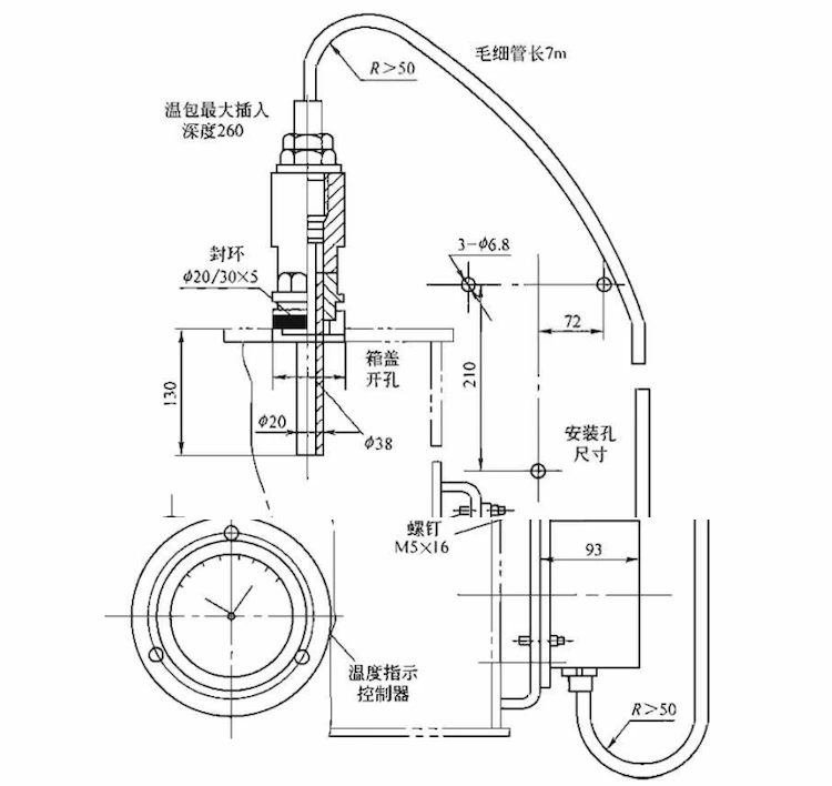
The signal thermometer is mainly composed of a temperature measuring bulb, a pressure gauge and a connecting capillary, as shown in the figure. It is made using the relationship between saturation pressure and temperature.
In addition to indicating the temperature, it can also realize temperature control or send a signal, also known as a pressure signal thermometer.
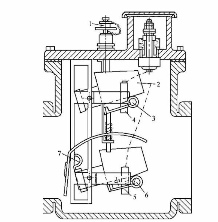
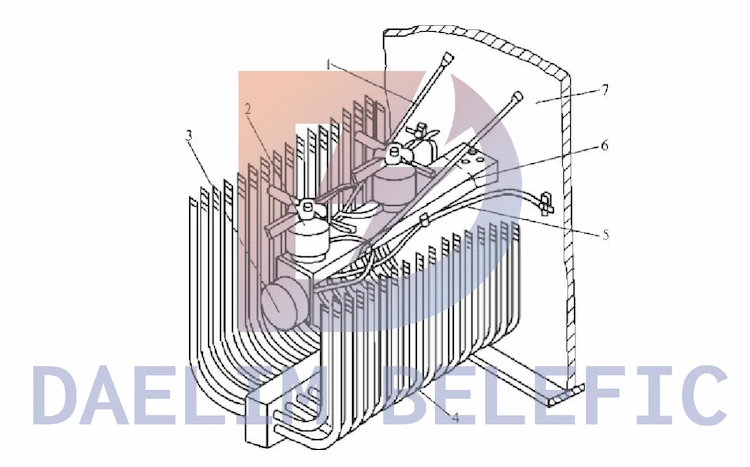
When a fault occurs inside the oil immersed transformer, the insulating material or oil at the fault will be decomposed, and gas will be generated.
The opening cup 2 is lowered, and the permanent magnet 3 is lowered to a certain position, so that the reed contact 4 is connected and an alarm signal is issued.
When there is a serious fault inside the oil immersed transformer, there is a large amount of gas gushing out, causing oil flow in the connecting pipe.
When the flow rate reaches a certain value, the baffle plate 7 is driven, and the baffle plate moves to a certain limited position, and the permanent magnet 6 makes the reed contact 5 connect, thereby cutting off all the power supplies connected to the transformer and protecting the transformer.
The bleed plug can release gas for testing.
Oil-immersed power transformer is an indispensable power equipment for power production and transportation. Transformer is also an important equipment for realizing flexible transmission of power grid. The production quality of transformer directly affects the operation safety of power grid.
In a word, the failure of oil-immersed transformers is caused by a variety of factors, and it is necessary to continuously summarize the causes of the failures to provide a scientific basis for future work, which will help improve work efficiency and quality, so as to achieve stable operation of oil-immersed transformers.
ELECTRIC, WITH AN ENGE-- DAELIM BELEFIC
After filling in the contact information, you can download the PDF.