
How to Choose Pad Mounted Transformer?
Table of Contents Selecting the right pad-mounted transformer requires careful consideration of several critical
ELECTRIC, WITH AN EDGE
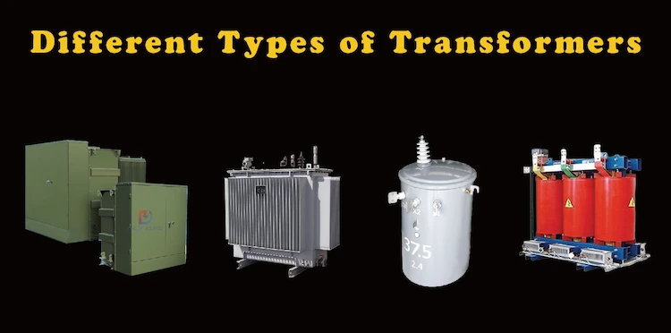
The transformer is the main equipment for power transmission and transformation. Different from other rotating machinery, it is considered a high-efficiency power conversion equipment. In real life, we see many different types of transformers. Including the two main types of power transformers and distribution transformers, and their specific products.
This article will tell you in detail what are the two main types of transformers, and explain 4 different types of transformers.
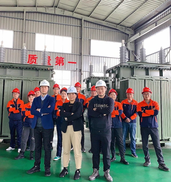
Daelim is a manufacturer with 16 years of experience in transformer production and sales, which allows Daelim to build up a strong and reliable team of engineers with rich experience.
This professional team of transformer design engineers can design and produce transformer solutions that meet your specific needs according to your needs, bringing you huge economic value.
At the same time, Daelim is deeply involved in the North American market, providing transformers for dozens of Bitcoin crypto farms. Therefore, their transformers have obtained many certifications such as IEEE, CSA, ANSI C.57, DOE, etc., which guarantees the quality of the transformers you purchase.
Power transformers are required in transmission networks with higher voltages.
400 kV, 200 kV, 110 kV, 66 kV, and 33 kV are the voltage ratings of the power transformer (kilovolts per second).
More than ninety percent of them have an MVA rating of 200 or higher.
It is mostly found in the grid’s production facilities and transmission facilities. They’re designed from the ground up to be as effective as possible all the time.
They have a substantially larger volume when compared to the distribution transformer.
There are several ways to do this, the most common being a step-down power transformer.
Core loss occurs because the transformer is underutilized throughout the day. Even yet, the copper loss is a function of the load cycle of the distribution network.
However, when a power transformer is connected to the transmission network, it is unlikely that there will be major fluctuations in load because it is not directly connected to the consumer end.
There will be constant losses in the transformer’s core and copper conductors due to its 24-hour operation.
If the voltage is low, a power transformer is more cost-effective. A decrease in the power transformer current causes an increase in I2R losses and voltage regulation.
In this class of transformer, lower voltages are available, such as 11 KV, 6.8 KV, 3.0 KV, and the standard voltage of 440 volts.
By lowering voltage levels at the end user’s end, distribution networks can change voltage levels in the power system by a factor of more than 200 MVA.
The primary coil of a distribution transformer is wound using insulated copper or aluminum wire.
An aluminum and copper ribbon is used to make the secondary winding of the transformer. Insulation is provided by a combination of oil and resin-coated paper.
440 220 V is used in the home, while distribution transformers of less than 33 KV are used in industrial applications.
Because it is smaller, quicker to install and has fewer magnetic losses, it is rarely utilized to its full potential.
Because its load is at its highest during the day and at its lowest during the night, the efficiency varies on the load cycle.
It is computed as All Day Efficiency because it does not operate under a steady load for 24 hours of the day.
Maximum efficiency of 60-70 percent is the goal for distribution transformers.
It is possible to categorize this transformer type based on the primary and secondary winding turns and the induced electromagnetic field.
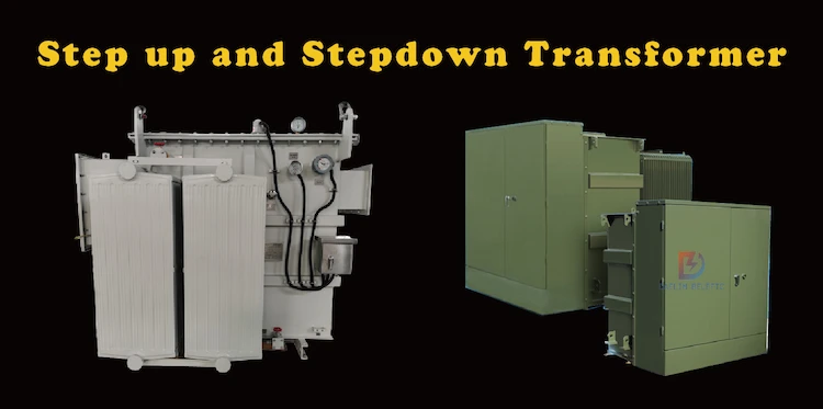
With the use of a step-up transformer, AC systems with high currents but low voltages can be converted to the opposite.
The primary winding of this transformer has fewer turns than the secondary winding, which has a greater number of turns.
There are various varieties of step-down transformers, including low-voltage, high-current, high-voltage, and low-current transformers.
The primary winding of this transformer has more turns than the secondary winding.
The output voltage can be reduced by a factor of two using “step down transformers,” as they are known.
Use the current transformer to monitor and prevent overheating and short circuits. High currents in a course that can’t be measured directly necessitate the employment of a current transformer.
The primary winding of the current transformer is wired with several measurement equipment, including an ammeter, voltmeter, wattmeter, and a protective relay coil. A proper current-to-phase ratio and right current ratio are required for secondary accuracy of the meter. The concept of “ratio” is very important in CT.
Vector sum of both excitation and secondary current reversals multiplied by current transformer turn ratio.
Instrument transformers can be used to modify the direction and amount of the current flow.
An instrument transformer’s most common purpose is to shield the secondary winding from high voltage and current. Instruments such as energy meters and relays can be securely isolated from the primary winding.
There are two types of instrument transformers.
When it comes to single-phase transformers, Faraday’s law governs the operation of the transformers.
Using alternating current (AC), the transformer transfers the current from one circuit to another while maintaining a stable frequency and voltage variation.
The transformer has two separate windings, as you can see. The load is connected to the secondary winding of an alternating current (AC) circuit after it has passed through the primary winding.
It is possible to convert three single-phase transformers into one three-phase transformer by connecting their primary and secondary windings in the same way as a three-phase transformer.
The secondary windings have been connected to each other.
A three-phase supply is the most prevalent method of generating, transmitting, and distributing electric power in industrial settings.
For the price of one three-phase transformer, three single-phase transformers can be built instead.
For three-phase transformers, you can utilize Star (Wye) or Delta (Mesh) three-phase connectors.
Current transformers quantify the total amount of current flowing via a single line conductor. It is impossible to separate the primary from the secondary.
Current transformers are believed to be the load circuit’s cable or busbar primary. The primary winding is typically defined as a single straight line.
They are linked in a way that only nature can. There is no physical interaction between them. When the transformer is powered up, it is impossible to remove the secondary.
CBCT is an example of a core-balanced transformer; these current transformers are used to sense the unsteady current flow in the circuit.
Using the multiple current transformer’s outputs, a single transformer converts numerous outcomes to a single result.
Measuring complexity, equipment installation costs, wiring costs, and so on are all reduced.
There is no primary winding in these. Instead, a window or hole in the toroidal transformer is used to carry the network’s current. In the case of a current transformer, the secondary can be taken with you. Digital tong tester, for instance.
Among the most common and essential transformer designs are the core-and-shell and core-and-shell types.
The primary and secondary windings of a closed-core transformer are wrapped around the ring of the core itself.
Laminations are used to build the transformer’s magnetic core, rectangular. Layers of laminated wood are butted against one another, creating a high resistance at the joints. Thus the alternate layer is built differently to avoid continuous joints.
By interlacing the primary and secondary windings, leakage flux is kept to a minimum.
As seen in the illustration below, half of each winding is placed on the core’s leg.
For convenience of construction, the primary and secondary windings are placed on separate limbs of the essence.
Thus, the insulation layer is sandwiched between the primary and secondary windings.
The low winding is almost always placed in front of the core, which results in less insulation being provided. The lamination is then inserted into the winding process.
The E and I laminations’ lengthy strips have been cut off. To reduce high-reluctance joints and eliminate continuous connections between sections, laminated parts facing one another are stacked differently.
The shell transformer has three legs.
The primary stem has all the flux, but only the core limbs convey it. Because of this, the central portion of the lb is roughly two times wider than the rest of it.
As a result, the central limbs have primary and secondary windings.
The high voltage winding is positioned outside of the low voltage winding in order to save money on insulation. It is placed on top of the cylindrical windings.
In an inner core transformer, the core is enveloped by the windings, even if the core is protected by an outer shell.
Once the laminations are cut, core type transformer laminations are cut in an L-shape, whereas shell type transformer laminating is elongated.
The cross-sectional area of a core-type transformer is square, but the cross-sectional area of a shell-type transformer has a cruciform two-slipped or three-stepped shape.
The core-type transformer necessitates a greater quantity of copper conductor since the windings are distributed over distinct legs.
Since the core type transformer has concentric coils, it is also a cylindrical or core winding transformer. Sandwich or disc winding transformers have low- and high-voltage windings in a shell-type transformer.
In addition, the core and shell varieties each have two limbs of change.
The core-type transformer’s mechanical strength is lower than the shell-type transformer’s because of the bracings in the shell.
The three limbs of the shell-type transformer meant that the core type transformer needed less insulation.
The lateral limbs of a shell-type transformer each carry half of the change, whereas the center limb carries the entire flux. The flux is uniformly distributed in a core type transformer.
Core-type transformer primary and secondary windings are on either side, while shell-type transformer windings are centrally situated in their respective transformers.
As a result, unlike a shell-type transformer, a core-type transformer has two independent magnetic circuits.
Since it contains two magnetic circuits, the core-type transformer has more losses than a shell-type transformer, which has only one.
Therefore, just a few of the core type transformers windings are removed for routine maintenance. Removing the transformer winding numbers for routine maintenance is a need.
Due to increased losses, a core-type transformer’s output is lower than a shell-type transformer’s.
Lastly, unlike a core-type transformer, the shell-type transformer winding is spread, allowing heat to be naturally dissipated.
A single-phase core type transformer can only be made with a single window. There appear to be two arms and two legs in all, based on this evidence. Both limbs are wrapped in both LV and HV windings.
Typically, one half of each winding is wrapped around one core limb, while the other half is wrapped around the other limb.
Additionally, the winding is first wrapped around the limb surface to insulate the core properly. All windings are shielded from each other by insulating the LV and HV windings adequately. LV and HV windings are arranged to cover both limbs of the device.
The transformer is more cost-effective in this configuration. Insulation costs between the grounded core and the HV winding are at their highest. The LV winding is positioned closer to nature to save on insulating costs.
On the other hand, cores with square or rectangular cross-sections are employed in smaller core type transformers.
Because a laminated square or rectangular cross-sectional center is simpler to create, wrapping around limbs with a square or rectangular cross-section is not tricky.
Using this method, it is possible to produce smaller transformers at a lower cost.
However, wrapping the winding conductor in square or rectangular shapes is difficult when dealing with large transformers.
Round cylindrical windings are ideal for getting the most out of copper conductors.
Because of this, there is a substantial amount of unutilized space between the cylindrical winding and the core. Because of the transformer’s size, this is not an intelligent strategy.
In addition, a stepped cross-sectional nature decreases these empty areas by carefully staging laminations of varying dimensions to achieve a nearly circular cross-section.
A one-, two-, or multi-stepped cross-section can be used, depending on the transformer’s dimensions and design and its cost-effectiveness and efficiency.
Transformers with cores suffer from flux leakage, which is their most significant shortcoming.
This configuration has a higher leakage flux than a shell-type transformer does. It harms the transformer’s performance and efficiency. However, it is still the ideal option for big transformers due to the ease of accessing the windings for maintenance.
If the outside winding of a shell-type transformer is damaged, the inner winding cannot be repaired without removing the outer winding.The center of a three-phase transformer has three limbs, which is significant. An LV and HV are winding for a phase in the three-phase system for each leg.
The center of a three-phase transformer has three limbs, which is significant. An LV and HV are winding for a phase in the three-phase system for each leg.
Table of Contents Selecting the right pad-mounted transformer requires careful consideration of several critical

The primary function of the pad mounted transformer is to serve as a critical distribution

A pad mounted transformer operates through electromagnetic induction, serving as a crucial distribution component that
After filling in the contact information, you can download the PDF.