ELECTRIC, WITH AN EDGE
A lot of consumers prefer 3 phase step-up transformers compared to 1 phase transformers.
But this depends on your situation and use case.
Usually, 220v to 480v step-up transformers are the ones commonly bought which can be utilized to turn step-up transformer single phase to 3 phase with the right 3 phase step-up transformer 240 to 480 wiring diagram.
To help you make the right purchase decision, DAELIM, a professional 3 phase step-up transformer manufacturer from China, will help you understand what 3 phase step-up transformers are capable of by explaining the elements above.
For starters, it is important to know what are the different kinds of transformer phases. So that you will not be confused as you go deep into the article.
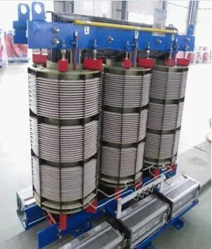
Three-Winding Transformer | Three-Phase Transformer
-Learn the fundamentals of the Three-Winding Transformer, including what is it, how does it work, common Three-Winding Transformers, Applications, and custom options.
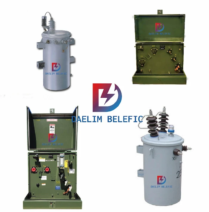
Electric Pole Transformer | Single Phase Transformer
-Learn the fundamentals of Electric Pole Transformers, including What is pole mounted distribution transformer, pole mounted transformer specifications, pole mounted transformer drawing, pole mounted transformer sizes and custom options.
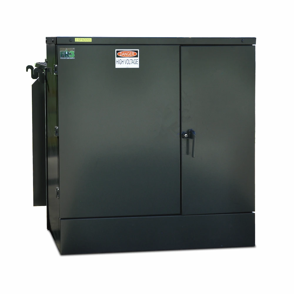
15+FAQ ABOUT THE 3 PHASE PAD-MOUNTED TRANSFORMER
-3 PHASE PAD-MOUNTED TRANSFORMER is a highly integrated transformer. It is widely used in power systems. Learn more about 3 PHASE PAD MOUNTED TRANSFORMER (including how to buy them) in this new guide.
To begin with, transformers are primarily AC or alternating current devices, which means that we need to know the phase relationships between primary and secondary circuits.
With DAELIM’s assistance, you will be able to plot the waveshapes for primary and secondary circuits and see the phase relations for yourself accurately.
When it comes to going from primary to secondary, the voltage will be stepped down with the use of a factor of ten, the current will then be stepped up by a factor of 10 which means that both current and voltage waveforms will be in-phase when going from primary to secondary.
For the transformer convention, it would seem like both voltage and current for two transformer windings are in sync or in-phase with each other, at least for the resistive load. This is considered sufficient.
What are the types of transformer windings ? What are the types of concentric windings?
However, it would be better to have an accurate idea of which way should it be connected to ensure proper phase relationships.
A transformer is actually nothing more than a set of magnetically-linked inductors, and as you know, inductors do not come with polarity marking of any kind.
If you were to look at a transformer that is unmarked, you could definitely not tell which way is it to hook or link a circuit to get it in-phase (or 180-degree out-of-phase) voltage and current.
Since the most common concern is practical, this means that transformer manufacturers have come up with a polarity marking that is standard to denote phase relationships.
This is also known as a dot convention, and it is nothing more than just a dot that is placed next to each corresponding leg of a transformer winding.
In a usual setting, transformers like the 3 phase step-up transformer, will usually come with a 3 phase step-up transformer 240 to 480 wiring diagram that will label where the wire will lead for primary and secondary wings.
In the 3 phase step-up transformer 240 to 480 wiring diagram, it is expected that there will be a pair of dots that is formed in an organized pattern that matches the transformer’s wirings.
However, there are times that the dots will eventually fade when “H” and “X” labels are being used as transformer winding wires, subscript numbers are usually used to represent both winding polarities.
The “1” wires or the H1 and X1, will represent where the polarity-marking dots will be usually be located.
The placement of these dots will be next to the top ends of both primary and secondary windings that will tell us whatever instantaneous voltage polarity is seen across the primary windings that are expected to be the same as that across to the secondary windings.
In simpler terms, the phase will shift from primary to secondary will be in zero degrees.
On the other hand, if the dots are on each winding of the transformer and are not compatible, the phase shift will be at 180 degrees between the primary and secondary.
This means that the dot convention will tell you which end of the winding is which that is relative to the other windings.
In the case that you want to reverse the phase relationship, you have the ability to swap the winding connections, but it must be done correctly in order to function right.
Basically, a phase-shifting transformer is like a step-up transformer single phase to 3 phase.
This type of transformer is primarily used to control the flow of active power on three-phase electric transmission networks.
Moreover, it does this through or by regulating the voltage phase angle difference between two nodes of the system.
This principle will rely on a phase-shifted voltage source injection into the line by a series-connected transformer, which is fed by a shunt transformer.
The configuration of this will be associated with a series transformer unit that will be responsible for inducing the phase shift.
In other words, it is a simple, robust, and reliable technology.
Preventive and curative control strategies that are implemented for power flow controllability. In terms of the preventive mode, the permanent shift will allow the redistribution of power flow, and this will relieve the network stresses in the event that there is a line outage.
In the curative mode, the phase shift is basically small, there are even times that its size is down to zero in normal operations, but this is automatically controlled to reduce the power flow on overloaded lines to prevent it from tripping out.
Active redirection of power flows will allow exploiting lines to be closer to their thermal limits.
Phase-shifting transformers are usually classified based on characteristics. Below are their characteristics:
Asymmetrical phase-shifting transformer is basically a transformer that generates an output voltage through a changed phase angle.
It basically creates an output voltage with an altered phase angle compared to the input voltage, but it has the same amplitude.
Symmetrical phase-shifting transformers generate an output voltage through a changed phase angle as compared to the i/p voltage, however with a similar amplitude.
On the other hand, an asymmetrical phase-shifting transformer does the opposite, and it creates an output voltage with an altered phase angle and amplitude that is in comparison to the input voltage.
Direct phase-shifting transformers are based on a core that is similar to 3 phase step-up transformers.
This means that the phase shift is obtained by connecting the windings in an organized manner.
For indirect phase-shifting transformers, this type of transformer is based on construction with two separate transformers.
The first one is a variable tap exciter that is used to regulate the amplitude of the quadrature voltage and one series transformer to inject quadrature voltages in the right phase.
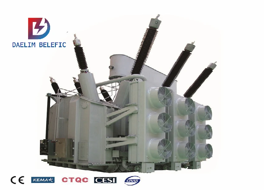
If you have been skimming through the different types of transformers, chances are, you have come across a step-up transformer, which is a very useful device that is commonly used by electrical companies, businesses, commercials, and other industries.
3 phase step-up transformers are very useful devices since you can easily multiply or divide voltages and currents in alternating circuits.
This type of transformer is capable of making long-distance transmission of electric power a practical reality.
An Alternating voltage can be increased or “stepped up” and current decreased or “stepped down” for reduced wire resistance and power losses along power lines that are connecting and generating stations with loads.
When an alternating current is being passed through the primary coil or the input of the transformer, there is a changing magnetic field that is created in the iron core.
The magnetic field that was produced will trigger the A.C current with the same frequency in the secondary coil or the output in the secondary that increases the received voltage in the secondary coil.
This way, this is called a step-up transformer as the secondary output voltage is significantly larger than the primary input voltage.
The amount of the output voltage in comparison with input voltage also increases twofold if the secondary coil has twice as many turns of the wire.
In simpler terms, a step-up transformer is capable of increasing the electricity voltage from low to high in the secondary coil that according to the requirement or the application.
The voltage will then be increased from the primary winding to the secondary winding in a way that it will make the power supply updatable with the said equipment.
This means that in a situation where an electrical device is being used that operates with 220v and the main power supply is only at 110v, a step0up transformer will help increase the 110v to a level that will with a lower requirement of the given device.
However, before you use any form of transformer with an electric appliance, make sure to match its wattage capacity.
At either the end of the generator or at the loads, voltage levels are normally reduced by transformers for safer operations. Moreover, this is less expensive equipment.
Now that you know what a transformer that steps up or increases the voltage from primary to secondary, on the other hand, are step-down transformers.
Which is specifically designed to be the opposite of a step-up transformer like 3 phase step-up transformers.
Basically, the operation of step-down transformers involves stepping down or decreasing the voltage from transmission levels to distribution levels.
Step-down transformers consist of a high turn count of the primary winding and a low turn count of the secondary.
A step-down unit converts high-voltage and low-current power into low-voltage high current power.
The larger gauge wire is used by the secondary winding which is necessary for increasing the current.
The primary winding that does not have to conduct a current may be made of smaller-gauge wires.
As mentioned, a step-down transformer is basically a type of transformer that converts high voltage current or H.V to low voltages or L.V.
This process starts from the primary side of the transformer to the low voltage and high current value on the secondary side of the transformer.
The reverse or opposite of this is the step-up transformer, which you just recently learned about.
In other words, this type of transformer still belongs to the static electrical equipment category that transforms electrical energy from the primary side windings to the magnetic energy.
And just like other transformers, this is not only its function or application since it is also a versatile device that is capable of doing many jobs.
Single-phase transformers are designed with cores that have two limbs that each carry equal parts of the primary and secondary windings or a center limb that carries both windings and two outer limbs.
A 1 phase transformer utilizes a single-phase alternating current.
This means that the transformer will have to rely on a voltage cycle the operates in a unified time phase.
The ratio of the primary or input windings to the secondary or output windings will determine the change in current.
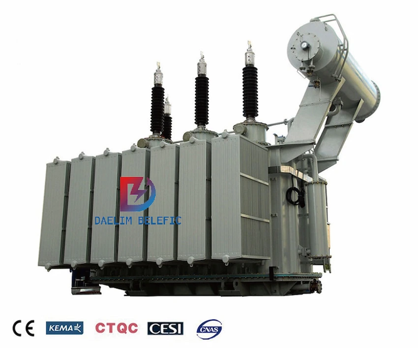
When it comes to the 3 phase step-up transformer, it is possible to make one through step-up transformer from single phase to 3 phase.
This means that three single-phase units can be interconnected to form a three-phase unit.
This is fed from a three-phase supply. It is expected that with this formation, there should be high reliability of modern transformers.
It even seems like there is little to almost none to be acquired by using them in preference or comparison to an actual three-phase unit.
The latter unit is much cheaper.
Moreover, there will be less weight, and lower energy losses as well than three single-phase transformers.
In terms of the installation costs, it would be cheaper as well.
When you need to find more than just existing transformers, Daelim’s Transformer Service Center can help you design and produce distribution transformers that meet your unique needs.
We have our own factory and a professional team of engineers, which can design and modify application requirements that meet all your conditions.
Download Resource
ELECTRIC, WITH AN ENGE-- DAELIM BELEFIC
After filling in the contact information, you can download the PDF.