
How to Choose Pad Mounted Transformer?
Table of Contents Selecting the right pad-mounted transformer requires careful consideration of several critical
ELECTRIC, WITH AN EDGE
Electronics transformer is widely used in electronic components, semiconductor devices and other connections.
Its principle is to convert alternating current into direct current.
Electronic Transformers are also known as electronic power transformers, solid state transformers.
This article will tell you in detail how it works, what it consists of, and how to link.
Low-power applications such as voltage step-up or voltage step-down, isolating circuits, impedance matching, and so on can benefit from electronic transformers.
When it comes to working with low voltage and low current, an Transformer and Electronics is just like an electrical transformer.
Kilo Herth (kHz) and Mega Herth (mHz) are two examples of high-frequency electrical transformers (MHz).
In addition, low-power electronic transformers are specifically built by Dealim for this purpose.
They are utilized in computers, RF equipment, and lights.
Electronic Transformers are used to supply high to alternating but low impedance in electronic circuits.
When applied to fluctuating potentials, they can be utilized to alter or maintain frequency responsiveness and wave form.
Moreover, electronic transformers, which are used to supply bias voltage to electron tubes in electronic equipment, must have the necessary bias voltage values to function properly.
Electronic transformers are smaller and lighter than traditional power transformers because weight and space are major considerations in the design of electronic equipment such as mobile devices.
In the world of electronic transformers, there are a variety of options given by Dealim.
To produce a high voltage from a low input voltage, flyback transformers (FBT) or line output transformers (LOPT) are used.
A pulse forming network (PFN) and a load are connected using pulse transformers.
They maximize power transfer efficiency by matching the impedance of the load to the PFN.
In order to drive a diode or a thyristor, a rectifier transformer generates a DC voltage or current.
RF transformers are used to match impedance across the RF band.
For the transfer of energy from one input to another in discrete packages, switching transformers, also known as switch mode transformers, serve as a storage element.
Transducers, regulators, and converters all utilize these electronic transformers.
For example, there are toroidal core and toroidal core electronic transformer kinds.
Applications that require high bandwidth and quick switching speeds use local area network (LAN) or telecommunications transformers.
Primary and secondary grounds are separated by the signal.
Hence, Electronic Transformers used to power high-speed switching devices like FETs and insulated-gate bipolar transistors are called gate drives (IGBTs).
Copper wire is wrapped around a cylindrical wire in a toroidal core transformer.
To avoid the magnetic flux from leading, electronic transformers are designed in this manner.
Analyzing winding turns and specs is essential to choosing electronic transformers and Dealim finds great pleasure performing this for the clients.
Step-up, step-down, variable, and one-to-one are all options for winding turns.
The operating temperature, power rating, operating frequency range, maximum primary voltage rating, and maximum secondary voltage rating are all characteristics of electronic transformers.
As more than one primary winding is required for Electronic Transformers that use different nominal voltages, the maximum voltage for the application is necessary.
The cost of an electronic transformer is determined by a variety of factors, including its kind, size, and intended use.
For example, a typical step-down transformer can be purchased for as little as 2$ to 3$.
While RF transformers or other specialized application transformers can be purchased for more than $15..
The principle of electromagnetic induction governs a standard step up and step down transformer.
The primary winding and secondary winding make up a step-down transformer.
The number of turns in the primary winding is higher than in the secondary winding.
The input power supply and the load are connected to the primary and secondary windings, respectively.
The step-up Electronic Transformer is the exact opposite of the step-down transformer in terms of function.
There are fewer turns on the primary winding than on the secondary winding of this coil.
As a result, it will deliver a higher output voltage to the primary winding than the input voltage.
Isolation transformers differ from typical transformers in that they are not connected to one other.
The number of turns on both of this transformer’s windings is the same. As a result, it does not alter the voltage in any way.
Basically, it acts as an electrical barrier between two separate circuits.
We know that electromagnetic induction is used to transfer electrical energy from a transformer’s primary winding to its secondary winding.
The primary and secondary windings are not electrically connected.
In this way the windings are completely isolated.
One sort of step-up transformer, the flyback, is constructed with electronic components.
It may step up the voltage from a low value, like 9V or 12V, to a high number, such up to 20000 V.
As a general rule, a transistor-based electrical switching circuit is linked to its primary side, which either turns on or shuts down the power supply.
A diode is attached to the secondary side of the circuit to prevent the reverse flow of electricity.
Basically, the flyback transformer transforms the DC supply into a higher voltage AC supply.
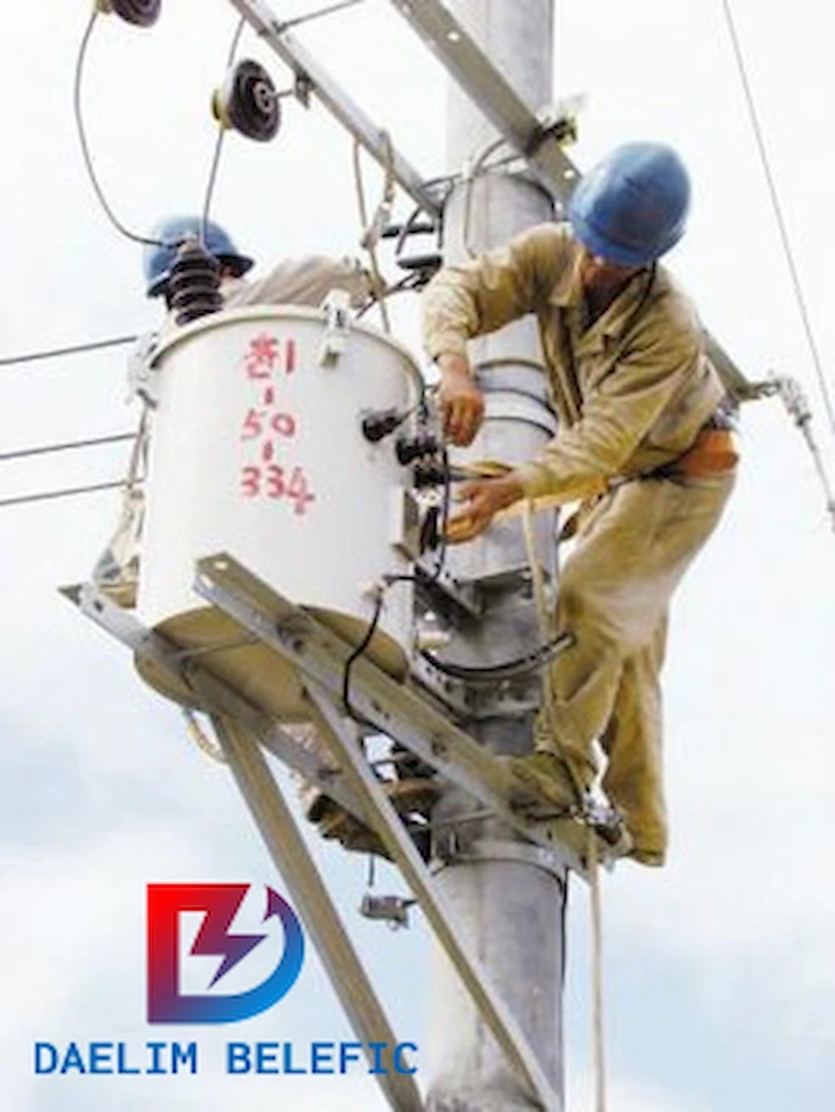
•Portable devices such as emergency lights, battery charger circuits, and so on use small electrical step-down transformers for voltage step-down applications.
•Flyback In Switch Mode Power Supply Circuits, transformers are employed.
•In order to maintain electrical isolation between two distinct circuits, transformer-based isolation is employed.
• Power supplies and power electronics often make use of pulse transformers.
To provide some context, the 69-KV transmission station is the source of this 34.5-KV subtransmission system. It’s (the source station).
Two delta to wye transformer banks make up the system.
For example, a 69 KV delta to a 34.5 KV wye Each Electronics Transformer’s wye-connected windings are grounded exclusively to the station grid.
There isn’t a neutral system that travels with the trains once they leave the station.
On the other hand, one 34.5 KV transmission line is fed by each transformer.
Lines A and B of the document.
The two lines travel to different stations on the same infrastructure.
This subtransmission system is linked to five different distribution substations.
A tie circuit breaker is installed at the 34.5 KV substation farthest from the source to connect the two lines (34.5 KV to 13.8 KV).
The five 34.5 KV substations are now linked together in a loop.
There are radial feeds for the three 34.5 KV substations that are fed by line B.
As such, there is a T-tapped connection between line B and line C about halfway between the source substation (69 kilovolts) and the furthest substation (34.5 kilovolts).
Two distribution substations are served by Line C, a radial.
A 34.5 KV-to-4.16 KV grounded wye to grounded wye bank, while the other has a 34.5 KV-to-4.16 KV delta-to-delta bank.
The bank in question is this one.
Therefore, there is a neutral conductor above the phase conductor on the transmission line.
Other names include “shield” and “static.” The transformer neutral is connected to the grounding grid, but you’ll observe a wire running up the pole and out with the phase conductors where the 34.5kv disconnects from the bus.
This wire is coming from the ground grid.
At 480VAC input, these Three-Phase transformers deliver voltage conversion that is smooth and steady.
The adoption of 15kVA and greater transformers that comply with the DOE 2016 regulations will cut operating expenses, lower the cost of ownership, boost profitability, and reduce overall greenhouse gas emissions.
Additional transformer types, such as drive Isolation Transformers, which reduce line current waveform distortion and thus improve the power factor of a motor drive load, are available in addition to energy-efficient and general-purpose three-phase transformers.
In addition to reducing voltage distortion, these transformers also help to prevent motor drives from negatively impacting other sensitive loads on the network.
Harmonic Supply voltage flat-topping is reduced and the overall power factor of the supply system is improved by using mitigation transformers.
The Environment Transformers are specifically developed for use with external control panels.
The range of applications, construction, rated power, and voltage level all have a significant impact on the design of 5 kV transformer oil capacity.
The range of 5 mva transformer parts types begins with generator transformers and finishes with 5 kv transformers for distribution.
A generator 5 kv transformer is a 5 kv power transformer that is directly linked to the power station’s generator.
Subsequently, the 5 MVA transformer current ratings are capable of powering up to 1000 MVA.
Approximate 1500kV can be reached by the 5 mva transformer current capacity voltage range.
A 5000-kva transformer price list can be found by clicking here.
In the range of 50 to 2500 kVA and a maximum voltage of 36 kV, distribution transformers of this type are typically manufactured.
Distributing electricity to users is done by the 5 MVa transformer at full load current.
The 5 mva inverter duty transformer is fed into a low voltage distribution network from the high voltage network.
Transformers with a 5 mva load capacity are available in two configurations: liquid-filled or dry.
At 2.5 MVA and up to 36kV, distribution transformers can be categorized as power transformers; at greater ratings, they’ll be called distribution 5 MVA transformer weight.
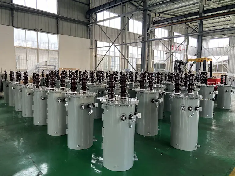
We are a top-tier 5 kV Electronics Transformer producer.
When it comes to the 5 kv power transformer price, our customers come from all walks of life and from all corners of the globe.
Different transformer specifications are frequently purchased by our buyers.
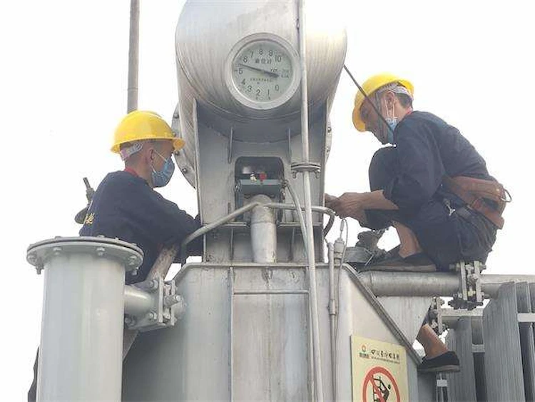
Also, we are certified to perform 5 kv transformer testing.
The 212.5 MVA transformer and 50-60 Km inter-substation distance were the original specifications for the 25kV traction system, which is commonly referred to as 25kV system.
Electric Traction has a unique ability to lure traffic via B routes, which gradually overloads the traction system.
Many new substations have been installed to the system in order to address the issue of voltage regulation.
This additional neutral portion in the system necessitates the Circuit breaker to be switched off and on while traveling through these neutral sections.
If the loco pilot is not warned at 500 meters and 250 meters, even though measures are taken, a flash-over may occur as the train passes from a live to a dead zone.
After careful consideration, the booster Electronics Transformer was removed, thus eliminating unneeded resistance and reducing voltage drop.
As a result, researchers are putting substantial effort into figuring out how to go from a 1x25kV pulley system to a 2x25kV one.
Since the present mast cannot accommodate extended period blocks, running a return conductor is the primary obstacle.
This is nearly impossible given the volume of traffic.
Running the return conductor on a different mast, of course, will be a pricey endeavor.
Hence, using a 25 kV traction voltage system allows locomotives to run from a single 25 kV traction system to two 25 kV traction systems without interruption.
However, the additional feeder wire and Auto-transformer provided at each SP and SSP come at a higher cost.
For overhead traction systems, 25 kV Single Phase is the most popular and globally accepted voltage standard.
All of the above must be designed, including the traction power supply system, overhead equipment, and the traction system for the vehicles.
Increasing OHE voltage is necessary.
The 225 kV system is designed so that the voltage at vehicle level remains at 25 kV. 50 kV is the chosen system for heavy-haul dedicated rail systems, when the locomotive is likewise restricted to that territory.
This traction system has a small number of manufacturers.
India’s Dedicated Freight Corridor project was originally intended for heavy haul, however the locomotive must operate in DFC and IR area, hence the 2x25kV power supply system was chosen.
In addition to developing and demonstrating the 25 kV Traction power system, SNCF also conceived, developed, and implemented it.
In order to speed up the electrification of the HWH-Bardwan section of the Eastern Railway, India worked with SNCF to switch from a 3000 V DC system to a 25 kV system as soon as it was finished.
Converted from 3000V DC to 1500V DC, the imported rolling stock was employed in the Mumbai Sub-urban system.
Download Resource
Table of Contents Selecting the right pad-mounted transformer requires careful consideration of several critical

The primary function of the pad mounted transformer is to serve as a critical distribution

A pad mounted transformer operates through electromagnetic induction, serving as a crucial distribution component that
After filling in the contact information, you can download the PDF.