
How to Choose Pad Mounted Transformer?
Table of Contents Selecting the right pad-mounted transformer requires careful consideration of several critical
ELECTRIC, WITH AN EDGE
Delta Wye Transformer is a three-phase electric power transformer design that uses delta connected windings on its primary and wye or star connected windings on its secondary.
The delta-wye transformer is the most common transformer connection globally because of its electrical configuration. The delta-wye connection is the most commonly used 3-phase transformer connection in power distribution by industry professionals when it comes to making proper transformer connections. To supply line-to-neutral, you can use the secondary as a neutral point.
In addition, industrial facilities frequently use Delta-Wye transformers. This setup is cost-effective because of the lower amp draw and lower heat generation associated with Delta configurations. As a result, less insulation is needed on the primary side. On the primary coils, minor wiring can be used and a neutral is available on the other side.
On the output side, a neutral wire can be provided. It can either be a single three-phase transformer, or three separate single-phase transformers that are connected together in series.
Delta-star transformer is a moniker for this type of transformer.
In addition, commercial, industrial, and high-density residential areas commonly use delta-wye transformers to supply three-phase distribution systems.
There are several examples, but one would be an 11-kV delta primary distribution transformer with no neutral or earth and a star secondary delivering a 3-phase supply at 415 V, with residential voltage 240 available between each phase and earthed neutral point.
On the other hand, when the transformer delta winding is used, third-harmonic currents can flow within the transformer, but they can’t flow out.
When using delta-wye transformers, the phase shift might be 30, 150 or 210 degrees.
As a result, they are incomparable to wye-wye transformers.
However, they can be paralleled with other delta-wye transformers of identical configurations and some different configurations.
The delta-wye transformer is the most common transformer connection in the world because of its electrical layout.
Moreover, the delta-wye connection is preferred by more power distribution industry specialists than any other 3-phase transformer connection. Why is it so well-liked?
In order to supply single-phase loads with line-to-neutral power, you can ground the neutral point using the secondary.
There are numerous uses for the delta primary.
The delta primary winding provides a better current balance for the primary source if the transformer secondary serves a considerable number of unbalanced loads.
Additionally, dry-type and liquid-filled transformers are the two main types.
Air is the most common cooling medium for dry-type transformers; some sealed dry-type transformers use nitrogen for cooling.
Most of the time, they’re used indoors with voltages up to 34.5 kV.
As a rule, liquid-filled transformers are best used in outdoor medium and high voltage systems.
The liquid is a great way to keep things cold.
Thus, the characteristics of the core and winding Voltage transformation necessitates the use of a transformer winding and magnetic core.
The core is made up of thin silicon steel laminations that minimize eddy current losses.
Exposure to an alternating magnetic field causes eddy currents to form in the core structure.
For transformer windings, copper and aluminum are the most popular materials. In terms of weight, aluminum is lighter than copper, but it has a higher resistance.
There are some advantages to using copper-wound transformer rotor coils over aluminum-wound rotor coils in terms of mechanical rigidity.
Hence, facilities that hold computer, communication, and data processing equipment frequently have third harmonic currents.
This third harmonic current should be trapped in the delta primary windings; yet, a small amount of third harmonic current continues to flow through the primary lines.
It is seen in the figure that the third harmonic currents remain trapped in the primary delta winding of a delta-wye transformer.
The delta–wye three-phase transformer connection is the most frequent.
Single-phase load can now be spread evenly among the three phases to neutral, rather than being confined to a single winding as is the case with traditional four-wire delta secondary configurations.
But, the entire delta–wye bank is rendered inoperable if one of the single-phase transformers fails.
In some cases, Delta–wye transformers can’t be paralleled with delta–delta and wye–wye transformers that don’t create any phase shift, as can be observed by the phasing symbols in this diagram.
There are several fundamental principles about the operation of polyphase transformers that may be learned by studying the delta–wye transformer.
On a voltage or current basis, the analysis can be carried out.
We’ll utilize current (or the flow of charge) instead of voltage (the potential difference or subtraction of two phasor variables) because current is more concrete and easy to understand.
Therefore, the delta–wye transformer has winding currents.
The arrows show the direction of the AC current at any given time, which is compatible with the dot convention.
Delta-connected high-voltage or wye-connected low voltage circuits must be examined first to begin the investigation.
In order to begin with, the wye-connected circuit is chosen since the line and phase currents in a wye-connected circuit are equal.
As a result of this connection between line and phase currents, the analysis becomes more simple.
Line currents in the low-voltage circuit are indicated by lower-case subscripts, whereas those in the high-voltage circuit are shown by uppercase subscripts.
To designate the low voltage circuit’s phase currents, we use the same convention as the line currents.
It is common practice to connect a high-voltage winding to a low-voltage winding in parallel when wiring a transformer.
The direction of the phasor angles changing from one electrical circuit to the next is specified by Daelim.
The positive-sequence currents and voltages on the high voltage side of a delta–wye (or wye–delta) transformer are 30° ahead of the positive-sequence currents and voltages on the low voltage side.
Furthermore, you should keep in mind that the 30° rule for determining standard connections is important to keep in mind.
No mention of primary or secondary is made.
These are the windings to which voltage is applied in a transformer’s primary windings.
Across the secondary windings, a voltage is induced.
The primary windings are usually the high-voltage windings, but this is not always the case in all cases.
A generator step-up transformer is a nice illustration of an exception.
Procedures for simplifying complex resistor networks are commonly called “delta-star” transforms because of the structure of their circuits.
The purpose of this computation is to convert a wye configuration to a delta configuration or a delta configuration to a wye configuration.
To convert an AC voltage to a stable DC voltage, the first step is to use a bridge rectifier circuit, which is a three-phase power system’s Delta design by Daelim.
Subsequently, the lead from the secondaries of three single-phase transformers connects them to a common point (neutral) in a wye configuration.
The line conductors are linked to the other lead from each of the single-phase transformers.
A wye is an arrangement that appears like the letter Y in an electrical schematic. It does not have a high leg like the delta transformer.
Primary winding turns divided by secondary winding turns is the ratio of a transformer’s primary phase voltage to the voltage of its secondary phase, which is expressed as a percentage.
There is a 2:1 ratio for standard delta/delta systems; however, a 4:1 ratio is used for standard delta/wye systems.
Adding to these, in a delta/delta system, the major phase voltage is typically 480V, and the secondary phase voltage is typically 240V.
In a typical delta/wye system, the secondary phase voltage is 120 volts if the primary phase voltage is 480 volts.
As far as phase voltage and current are concerned, delta and wye transformers are very different.
Moreover, more than simply the formulas you employ for transformer calculations are impacted by these discrepancies.
Harmonic distortion in an electrical system can be reduced using a combination of delta/delta and delta/wye transformers.
The secondary transformer phases (windings) or line conductors must be balanced before you can appropriately size a delta/wye transformer.
For wye transformers, the process of balancing the panel is the same as balancing the transformer.
You can size the wye transformer based on the load on each phase after you’ve balanced it.
However, unbalanced loads can be higher than the nominal kVA when dealing with high-harmonic loads.
As a result, the transformer must be precisely matched to the projected load in order to achieve a suitable level of efficiency or power quality.
When faced with a situation like this, one solution is to use their own delta/delta transformer to power high-harmonic loads.
Another option is to double the neutral and supply them from their own delta/wye.
The method you select will be determined by the nature of your loads and the efficiency with which your power distribution system is laid out…
As an illustration, you may connect your computer’s switching power supplies (which are connected to a delta/delta transformer) to a delta/wye transformer for power.
The absence of a neutral connection would considerably minimize the presence of harmonics in the primary system.
Depending on the individual loads and the overall electrical system design, grounding considerations can make it an unsatisfactory solution.
Keep in mind that this is just one method of resolving poor power quality by combining various transformers.
Further, some transformer layouts may be necessary because of uptime or power quality concerns with complicated loads, as in the prior example.
Because only those who are fluent in both delta and wye computations are capable of doing so.
The appropriate loading of transformers is a further concern.
As a general rule of thumb, aim for a loading percentage of at least 80%.
Overloading the transformer, on the other hand, causes core saturation, which results in distorted waveforms as the output.
In addition, overheating of the loads is caused by the clipped peaks common to saturated transformers.
In order to obtain basic power quality and fair efficiency, you’ll need to run transformer calculations because of the problem with transformer loading.
As a result, choosing a transformer shouldn’t be overly simplistic.
The nameplate kVA is usually the best way to perform all computations.
The distribution system should then be designed as though all loads were linear.
Determine which loads are high harmonics after that, such as electronic ballasts, computer power supplies and motors with variable loads.
A transformer supplier can help you build a good solution at this stage.
Therefore, Delta and wye transformer calculations are critical to making sure that you get a quality installation if you’re specifying transformers or considering adding loads to existing transformers.
If you’re having trouble with “unexplained” system trips or poor power quality, this skill will come in handy.
If you want to improve your electrical calculations skills, you can buy a workbook or do the work yourself when working on electrical projects.
Daelim electrical setups that use solar, wind, or traditional generators necessitate the use of grounding transformers.
When it comes to providing effective grounding, a magnetic grounding device is a cost-efficient option.
A grounding transformer, also known as a neutral grounding transformer or ground separation, is often required in systems where a delta or ungrounded wye connection is employed.
Typically, these bespoke magnetics are supplied by Daelim in a zig-zag or autotransformer design.
Because there is virtually no current flowing through the windings of a grounding transformer during normal operation, transformers of this type are not sized in terms of kVA.
Depending on the monitoring and interrupting mechanisms employed, the current will surge significantly during a fault but only for a few cycles or seconds.
Additionally, the grounding transformer is frequently required to supply a small quantity of continuous electricity.
However, systems are designed to trigger when the neutral current exceeds a predetermined threshold.
If the transformer’s design doesn’t overheat during regular operation, this trip limit would be regarded as the continuous rating.
If the continuous rating is unknown, a minimum value of 3% of the short-duration fault current should be taken into account.
As a first step, the distribution transformer is susceptible to a number of malfunctions.
As soon as a problem is discovered, a parameter’s value may change from its normal state to a different state.
Weather-related factors such as high winds, trees crashing into power lines, and malfunctioning machinery all contribute to outages.
Under normal or safe operating conditions, the transformer covered by the power system network operates at normal voltage and current.
The values of voltage and current depart from their limitations when there is a problem.
That’s why the transformer could be killed if you don’t ground the transformer neutral.
On the other hand, electric devices in power systems may have failures, as previously stated.
The transformer is not an exception in this scenario.
In the power system, short circuit faults are a typical problem.
The three-phase line to ground fault is the danger in a short circuit fault.
This is a common defect that develops between the ground and the three phases.
Although it is rare to see such a mistake arise.
There is a 2-3% chance of this happening.
Electricity, on the other hand, must be absolutely safe.
A person can experience a huge shock if any of the points in the system accidentally connect to the ground.
It’s possible that this is the end.
You should know that soil resistance is substantially higher, despite the fact that soil type affects it.
For this reason, ground faults can be greatly minimized in the event of short circuits or 3-phase line to ground accidents because of their high resistance.
However, if the soil has a lot of stones, the resistance will be higher.
As a result, the majority of substations are built using stones.
Earthing the neutral point has another purpose as well.
Creating a reference voltage is what this is all about.
Delta wye grounding is an unusual arrangement.
There is no way this system can handle a single-phase load.
It has its advantages as a well-established framework. There are several drawbacks to this grounding setup.
It is not possible to have equal phase-to-ground voltages.
The phase-to-neutral winding voltage sets the system voltage relative to ground.
System configurations like this one are rather common, though.
There are no differences in phase-to-ground voltages.
480 Y/277 V and 208 Y/120 V are the most common voltages in this area.
Electrical substations typically employ this arrangement.
A result of its effectiveness in protecting against line-to-ground problems.
First, you should take note that on the primary of a delta-wye transformer, there are delta-connected windings. At the same time, on the secondary, there are wye/star-connected windings. On the wye output side, a neutral wire can be provided. It can either be a single three-phase transformer or three separate single-phase transformers. The term “delta-star transformer” can describe the same thing.
For three-phase distribution systems, delta wye transformers are commonly found in commercial, industrial, and high-density residential buildings.
However, consider a distribution transformer with an earthed neutral operating on three 11-kV phases, a delta primary supplying three-phase 415 V power with the domestic voltage of 240 available between each phase and the earthed neutral point, and a star secondary providing a 3-phase 415 V power supply.
You can ground the neutral point using the secondary to supply single-phase loads with line-to-neutral power.
Hence, the primary delta serves a variety of purposes. The delta primary winding provides a better current balance for the primary source if the delta-wye transformer secondary supplies many unbalanced loads.
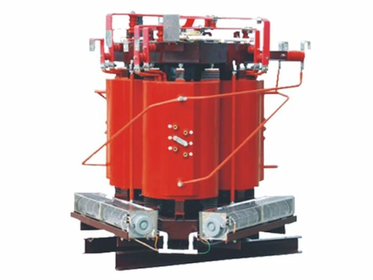
Dry-type and liquid-filled transformers are the two main types. Air is the most common cooling medium for dry-type transformers, some sealed dry-type transformers use nitrogen for cooling. They’re typically used for indoor use and up to a maximum voltage of 34.5kV.
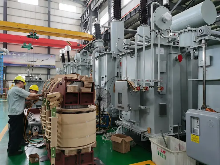
On the other hand, delta-wye transformers filled with liquid are commonly found in medium- and high-voltage settings, such as the outdoors. It’s a great way to cool things down. The next step is to examine a standard delta wye transformer costume.
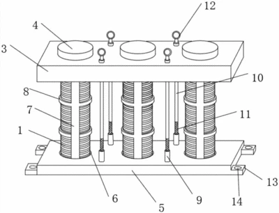
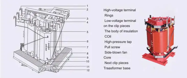
Winding and magnetic core are required for voltage transformation. A silicon steel core reduces eddy current losses by using thin laminations. Electromagnetic fields induce eddy currents that travel through the core structure.
For transformer windings, copper and aluminum are the most common materials.
In terms of weight, aluminum is lighter than copper, but it has a higher resistivity.
There are some advantages to using copper-wound transformer rotor coils over aluminum-wound rotor coils in terms of mechanical rigidity.
Computer, communication, and data processing facilities are common locations for harmonic currents. This third harmonic current should be trapped in the delta primary windings; however, a minor third harmonic current flows through the primary lines. The primary delta winding of this delta-wye transformer is where the third harmonic currents are held in check.
Therefore, if you’re unsure which delta wye transformer connection is best for you, do some research before purchasing.
When the transformer delta winding is used, third-harmonic currents can flow within the transformer, but they can’t flow out.
Thus, the phase shift introduced by a delta-wye transformer can be 30, 150, 210, or 330 degrees. Consequently, wye-wye and delta-delta transformers cannot be used parallel with these devices. However, delta-wye transformers can be paralleled with other delta-wye transformers with identical configurations and some other configurations.
In terms of connections, the delta–wye is the most common. In contrast to a four-wire delta secondary, which places the entire single-phase load on a single winding, the wye-connected secondary allows the three phases to be neutral to share the single-phase load.
The delta–wye bank will go out of service if just one of its single-phase transformers fails.
For this reason, it is impossible to compare the delta wye transformer with other types of transformers, such as delta–delta or wye–wye, which have no such phase shift.
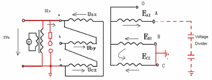
The delta–wye transformer is an excellent example of how polyphase transformers work, and it teaches us a lot. Either a voltage or a current basis can conduct the analysis. This is because voltage, potential difference or phasor subtraction is challenging to visualize, so current is used as a basis for analysis because current can be easily understood.
To add, Delta-connected high-voltage or wye-connected low voltage circuits must be examined first to begin the analysis. Wye-connected circuits are chosen because they have a similar line and phase currents, in the transformer winding, that can be used as starting points for analysis. As a result of this connection between line and phase currents, the analysis becomes more straightforward.
Lower-case subscripts denote line currents in the low voltage circuit. In contrast, line currents in the high voltage circuit are denoted by upper-case subscripts. All phases are labeled in a low voltage circuit because they share the same corresponding line currents. An exceptionally high voltage winding corresponds to the low voltage winding drawn parallel to it when drawing transformer windings.
Furthermore, it specifies how the phasor angles change from one electrical circuit to the next. There is 30° more current and voltage on the high-voltage end than on the low-voltage end in a standard delta–wye, or wye-delta, transformer configuration.
To establish a standard connection, placing the high-voltage phasors 30 degrees ahead of the low-voltage ones is customary. There’s no mention of elementary or secondary education in this passage. These are the windings to which voltage is applied, the primary windings of a delta wye transformer. The secondary windings receive an induced voltage.
The primary windings are usually high-voltage windings, but this is not always the case in all cases.
Delta Wye Calculation is known as the “Y-” or “delta star” transformation because of the shape of the circuits simplified by this transformation. Converting wye to delta or delta to wye is the goal of this calculation, which is used for circuit analysis to make it easier.
This first step in converting AC voltage to stable DC voltage is performed by a bridge rectifier circuit that uses a Delta configuration, a three-phase power system.
For high-harmonic loads, the maximum unbalanced load may be larger than the nominal kVA. When matching the delta wye transformer to the projected load, you’ll need high precision if you want decent efficiency or power quality.
Their delta wye transformer, in this case, can supply High-harmonic loads. Instead of double the neutral, you might use a delta/wye to supply both the neutral and the supply. The method you select will be determined by the characteristics of your loads and the efficiency with which your power distribution system has been designed and implemented.
You could use a delta/delta transformer to feed your computer loads, switching power supplies, from a delta wye transformer. Because there is no neutral connection, harmonics would be considerably reduced in the primary system.
In addition, the delta/delta transformer itself and the interplay between delta/wye and delta/wye will also reduce harmonics. If you notice, the question of whether or not to implement a design like that uses the word may. Because of grounding considerations, the total electrical system may not be able to support this method. Keep in mind that this is just one of several approaches to fixing power quality issues by combining transformers.
Complex loads may need a mix-and-match approach to transformer layouts due to uptime or power quality concerns. Only those fluent in both delta and wye computations can do so.
On the other hand, the proper loading of the transformer is also a concern. A good rule of thumb is to aim for 80% loading. On the other hand, overloading the transformer causes core saturation and produces distorted waveforms as a result. Saturated transformers’ clipped peaks induce overheating in their loads. For essential power quality and appropriate efficiency, you will need to make transformer calculations because of this issue of transformer loading.
As a result, it’s critical to avoid simplifying the selection process for transformers. The nameplate kVA is usually the best way to perform all computations. Finally, you should design the distribution system as if all loads are linear. Then you can figure out which devices, such as computer power supply and variable-load motors, have significant harmonic content. You can now effectively collaborate with a transformer supplier to build an adequate remedy.
The use of solar, wind or traditional generators and grounding transformers is essential in many electrical installations. In three-phase three-wire systems, a magnetic grounding device is cost-effective to provide effective grounding.
In connection, it is common for grounding transformers to be used in systems with a delta or ungrounded wye connection, requiring a neutral ground path or ground isolation. Typically, these custom magnetics are supplied by Hammond Power Solutions in a zigzag or autotransformer configuration.
When used in ungrounded wye or delta-connected power systems, grounding transformers provide a path to ground that is relatively low in impedance, which keeps the system neutral at or near ground potential, as well as a source of ground-fault current during line-to-ground faults and a limit to the magnitude of transient over-voltages when restrained.
On the other hand, the zigzag autotransformer is the most common design in terms of flexibility, size, and cost. Since the windings of a grounding transformer carry little to no current in regular operation, their kVA ratings are not used to determine their size. Depending on the monitoring and interrupting methods used, the current will increase significantly during a fault but only for a few cycles to a few seconds.
Additionally, a small amount of current should flow through the grounding transformer. The neutral current will be zero in a perfectly balanced system. Still, systems are designed to trip at a higher limit than this. To ensure that the design of the transformer does not overheat during regular operation, this trip limit is considered the continuous rating. It is recommended that a value of at least 3% of the short duration fault current be used if the continuous rating is unknown.
When the distribution line’s power transformer is in use, it is susceptible to many problems. The parameters’ values can fluctuate between normal and abnormal when a problem arises until the problem is resolved. Stormy winds, falling trees on the line, and other mechanical failures are responsible for power system outages.
Hence, power system transformers operate at their standard voltage and current ratings in safe conditions. The voltage and current values deviate from their limits when there is a problem. Transformation can suffer fatal damage if they aren’t grounded properly.
The transformer isn’t an exception in this case. A short circuit fault is a common problem in the power system. The three-phase line-to-ground fault is the greatest danger in a short circuit. Faults between phases and the ground are most common, even though these faults are sporadic. The chance of this happening is between 2% and 3%. Electricity, on the other hand, must be safe. Any of the system’s points that accidentally connect to a surface can cause a significant shock to a person’s body.
As such, soil resistance is much higher, even if the soil type is different. Because of the high resistance of the ground, a short circuit or three-phase line-to-ground accident can be significantly reduced when the soil is littered with rocks and the resistance increases. As a result, the majority of substations are built with stones. Earthing the neutral point serves a second purpose, as well. Creating a reference voltage is what this is all about.
A power system’s neutral grounding is critical because it affects its availability, short circuit withstands, transient overvoltages, basic insulation level, and other factors.
Additionally, a ground-fault zero-sequence current path is provided by grounding transformers, which create a grounded neutral connection on an ungrounded three-phase system, similar to a three-wire system supplied from a delta secondary. In an ungrounded transformer, they also allow the flow of the exciting current’s triplen-harmonic harmonics.
Low zero-sequence impedance and low no-load losses are two of the primary goals of grounding transformer design, hysteresis and eddy current losses. These factors directly impact grounding’s efficiency and cost.
Three-phase systems can benefit from grounding transformers, which are used to connect an ungrounded wye or delta-connected system with the ground.
Furthermore, an earthing system for the network includes grounding transformers. By providing a return path for current to a neutral, delta-connected systems can accommodate phase-to-neutral loads.
Because of their low impedance, grounding transformers help keep systems neutral by dissipating transient overvoltages when they are restricted to the ground. They also act as a source of ground-fault current in the event of a malfunction involving a connection to the earth.
For most grounding transformers, a single-winding transformer is used with zigzag windings. Still, wye-delta winding transformers can also be used.
In power plants and wind farms, neutral grounding transformers are standard.
Finally, when a delta-connected transformer feeds a system, a neutral grounding transformer may be used on a high-voltage (sub-transmission) system, such as a 33 kV system. In the event of a line-to-ground fault, a resistor or arc suppression coil can be used to limit the fault current flowing through the transformer’s grounding point.
Download Resource
Table of Contents Selecting the right pad-mounted transformer requires careful consideration of several critical

The primary function of the pad mounted transformer is to serve as a critical distribution

A pad mounted transformer operates through electromagnetic induction, serving as a crucial distribution component that
After filling in the contact information, you can download the PDF.