The power transformer is the most critical primary equipment in the substation. Its main function is to increase or decrease the voltage of electrical energy in the power system to facilitate the reasonable transmission, distribution, and use of electrical energy.
This article analyzes the selection and operating characteristics of power transformers in power supply and distribution systems.
Selection of Power Transformer: The Ultimate FAQ Guide
Classification of Power Transformers
There are many types of power transformers, which can be classified according to the number of phases of the power transformer, voltage regulation mode, winding form, winding insulation and cooling mode, connection group label, etc.
Power transformers can be divided into single-phase transformerand three-phase transformer according to the number of phases.
According to the voltage regulation method, power transformers can be divided into two types: no-load voltage regulation and on-load voltage regulation.
Power transformers can be divided into two-winding transformers, three-winding transformers, and autotransformers according to the winding form.
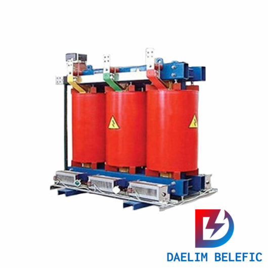
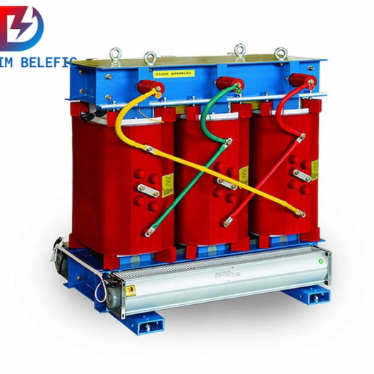
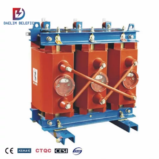
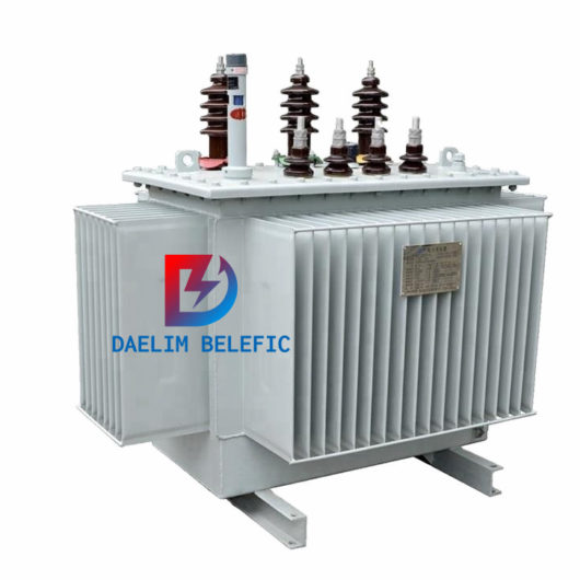
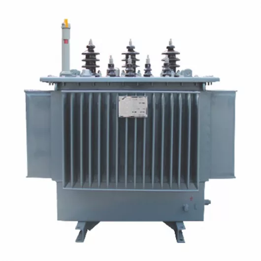
Power transformers are classified according to winding insulation and cooling methods, including oil-immersed transformer, dry-type transformer, etc.The cooling methods of oil-immersed transformers include self-cooling, air-cooling, water-cooling and forced oil circulation cooling methods. There are two cooling methods for dry-type transformers: self-cooling and air-cooling. Air-cooling can improve the overload capacity of dry-type transformers.
Distribution transformers are classified according to the connection group number, and there are two common types: Yyn0 and Dyn11. Compared with Yyn0 transformer, Dyn11 transformer has the following advantages:
1) The low-voltage side single-phase grounding short-circuit current is large, which is beneficial to the removal of the low-voltage side single-phase grounding short-circuit fault;
2) Strong load capacity to withstand single-phase unbalanced load;
3) The delta connection on the high-voltage side is beneficial to inhibit the 3n harmonic current from being injected into the power grid. Therefore, Dyn11 transformers are used more and more widely in low-voltage power grids in the form of grounding of TN and TT systems.
In addition, taking into account the requirements of lightning protection, Yzn11 transformers should be used in areas subject to thunderstorms and areas with high soil resistivity. The basic structure of a power transformer includes the core and the primary and secondary windings. The new S11-MR three-phase coil-core fully sealed distribution transformer has great improvements in structure and materials. Its main feature is that its core is coiled and annealed from crystalline-oriented high-quality cold-rolled silicon steel sheets, which reduces the traditional core. The air gap of the joint, the noise is significantly reduced, and its no-load loss is 30% lower than that of the S9 product on average.
Rated Capacity and Actual Capacity of Power Transformer
The rated capacity of a power transformer is the maximum apparent power that can be continuously output within the specified service life under specified ambient temperature conditions.
The service life of a power transformer mainly depends on the life of the insulation material of the transformer winding, which is directly related to the temperature of each part of the power transformer during operation.
In operation, if the allowable temperature rise is exceeded for a long time, the speed of insulation aging will be accelerated. Even if there is no insulation damage accident at that time, its life will be greatly shortened. The insulating materials used in power transformers are classified into 5 grades according to their heat resistance, as shown in the following table.
Insulation class
A
E
B
F
H
Heat resistance temperature /℃
105
120
130
155
180
Stable temperature rise /℃
65
80
90
115
140
When the transformer is in operation, the temperature difference of each part is very large, the temperature of the wire is the highest, the core is the second, the temperature of the insulating oil is the lowest, and the oil temperature of the upper layer of the transformer is higher than the oil temperature of the lower layer. Generally, when the hottest temperature of the transformer winding insulation is between 95°C and 98°C, the transformer can operate continuously for about 20 years. The test shows that: every 8°C increase in the temperature of the transformer windings, its life will be reduced by half. The temperature of the winding is not only related to the load of the transformer but also affected by the ambient temperature.
The ambient temperature conditions for normal use of power transformers are: the highest temperature is +40°C, the highest daily average temperature is +30°C, and the highest annual average temperature is +20°C. The temperature rise of the top oil of the oil-immersed transformer must not exceed the surrounding temperature. 55°C.
It is generally stipulated that if the annual average air temperature θ0.av ≠ 20°C at the installation site of the transformer, the capacity of the transformer will be reduced by 1% for every 1°C increase in the annual average temperature. Therefore, the actual capacity of the transformer should be included in a temperature correction coefficient Kθ.
For a transformer installed outdoors, its actual capacity is:
ST=KθSN=[1-(θ0.av-20)/100]SN
In the formula, SN is the rated capacity of the transformer. For transformers installed indoors, due to poor heat dissipation conditions, the ambient temperature of the transformer in the center of the room is generally about 8°C higher than the outdoor temperature, so its capacity has to be reduced by 8%. That is, the actual capacity of the indoor transformer is:
ST=KθSN=[0.92-(θ0.av-20)/100]SN
The normal overload capacity of power transformers
The overload capacity of a power transformer refers to the output power of the power transformer in a short period of time, and its value may be greater than the rated capacity. For many times, the actual load of the transformer is less than its rated capacity, the temperature rise is lower, and the insulation aging speed is slower than the normal speed. Therefore, the transformer has a certain short-term overload capacity without shortening the normal service life of the transformer insulation.
The overload of indoor oil-immersed transformers should not exceed 20%, and the overload of outdoor oil-immersed transformers should not exceed 30%. Dry-type power transformers generally do not consider normal overloads.
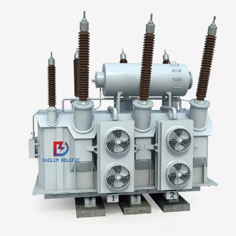
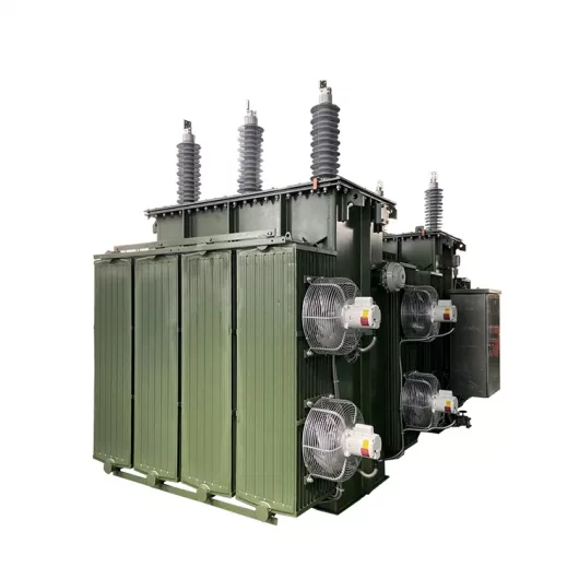
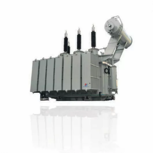
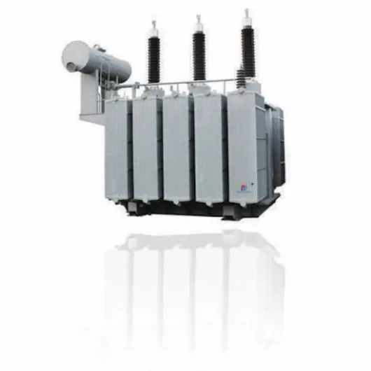
220 kv power transformer
Accident overload capacity of power transformers
When an accident occurs in the power system or factory substation, in order to ensure the continuous power supply of important users and equipment, the transformer is allowed to operate with a large amount of overload in a short time, which is the accident overload. The allowable accident overload multiples and times of oil-immersed transformers are shown in the following table.
If the overload multiple and overload time of the transformer exceed the allowable value, the load of the transformer should be reduced according to regulations
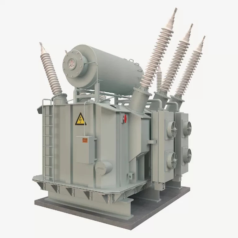
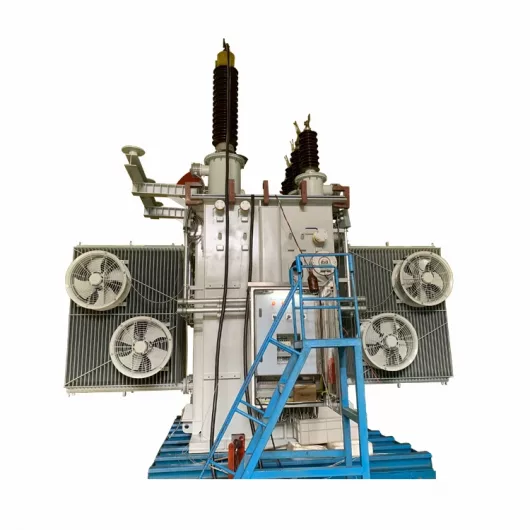
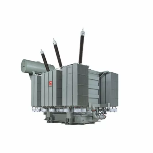
138 kv power transformer
Selection of the number of main power transformers in the substation
The following principles should be considered when selecting the number of main transformers:
Under normal circumstances, you should first consider choosing a transformer;
There are the following situations for choosing two or more transformers.
(1) For substations with a large number of primary and secondary loads, two transformers should be used so that when one transformer fails or is overhauled, the other transformer can continuously supply power to primary and secondary loads to meet the requirements Power supply reliability requirements.
(2) For substations where seasonal load or day and night load changes greatly and are suitable for economic operation, two transformers can also be considered.
(3) For general user substations other than the above, if the load is concentrated and the capacity is quite large, although it is a three-stage load, two or more transformers can also be used.
When determining the number of main transformers in the substation, the development trend of the load should be taken into consideration and an appropriate balance should be reserved.
Selection of Main Transformer Capacity in Substation
The mainstream transformer capacity grade on the market adopts the R10 capacity series. The transformer capacity grade of this series is increased by 1.26 times, such as 100kVA, 125kVA, 160kVA, 200kVA, 250kVA, 315kVA, 400kVA, 500kVA, 630kVA, 800kVA and 1000kVA.
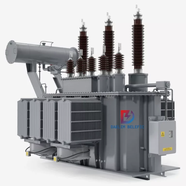
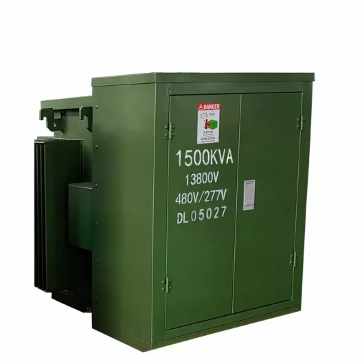
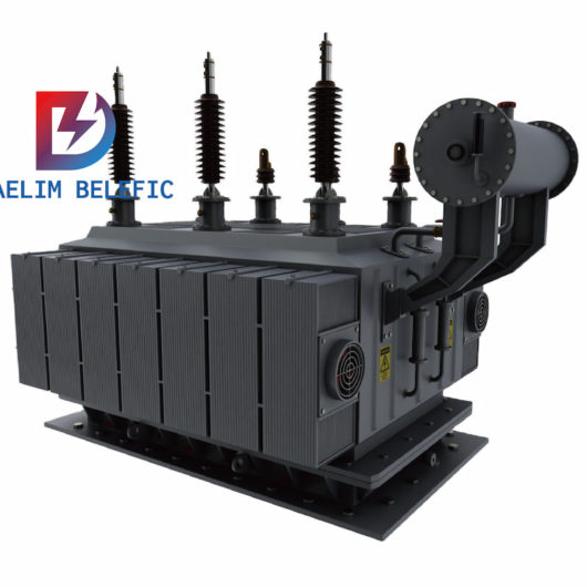
69 kv power transformer
Substation with only one main transformer. The transformer capacity ST should meet the needs of the total calculated load S30 of all electrical equipment, that is, ST ≈ SN ≥ S30;
For substations with two main transformers, the capacity ST of each transformer should meet the following two conditions:
(1) When any transformer is operating alone, it should meet the needs of 60%~70% of the total calculated load S30;
(2) When any transformer is operated alone, it should meet the needs of all primary and secondary loads.
Generally, the single capacity of the main transformer of the workshop substation should not be greater than 1000KVA (or 1250KVA). This is mainly considering that the transformer can be closer to the load center of the workshop to reduce the power loss, voltage loss and non-ferrous metal consumption of low-voltage distribution lines.
Appropriate consideration should be given to the development of the load. Generally, the growth of the electric load in the next 5 to 10 years should be considered, leaving a certain amount of leeway. At the same time, the normal overload capacity of the transformer should be considered.
Through the analysis of the operating characteristics of power transformers and how to choose the main transformer, it is hoped that workers engaged in substation operation will combine the actual situation of the unit, such as the selection of the main wiring scheme of the substation, and through the technology of several more reasonable schemes.
After economic comparison, the best is determined, and at the same time, the mastery of the performance of the power transformer is improved during operation.
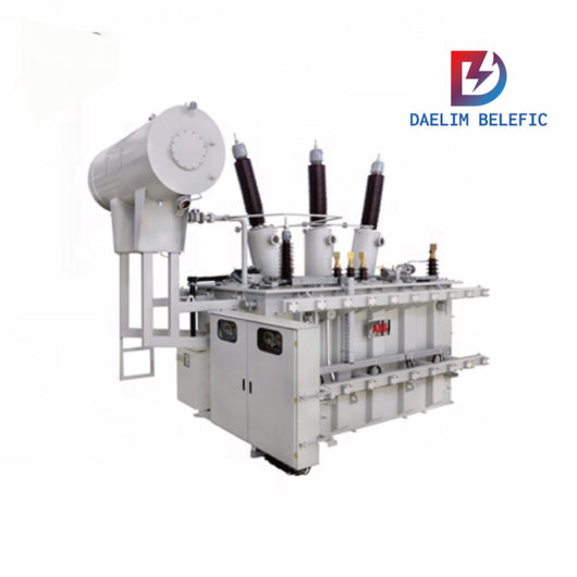
Custom PowerTransformer
When you need to find more than just existing transformers, Daelim’s Transformer Service Center can help you design and produce distribution transformers that meet your unique needs.
We have our own factory and a professional team of engineers, which can design and modify application requirements that meet all your conditions.