
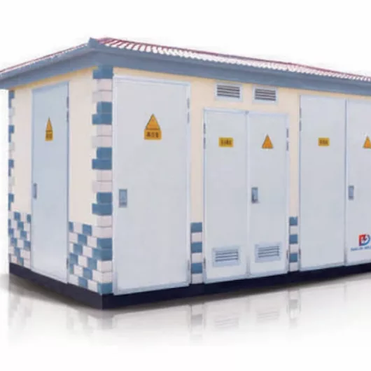
How to Choose Pad Mounted Transformer?
Table of Contents Selecting the right pad-mounted transformer requires careful consideration of several critical
ELECTRIC, WITH AN EDGE
A large number of complete sets of automatic tracking compensation arc suppression devices and low-resistance grounding devices are installed in the distribution network, and the Neutra grounding transformer is an important part of its matching.
The performance of the grounding transformer directly affects the performance index and safe operation of the automatic tracking compensation arc suppression complete set and the small resistance grounding device, and even affects the setting and safe operation of the power grid relay protection.
The main transformer of 6kV and 10kV distribution network has no neutral point. When choosing arc suppression coil or small resistance grounding method, a matching grounding transformer must be installed.
The grounding transformer is used to provide a grounded neutral point for the three-phase power grid. The neutral point of the Earthing Transformer can be grounded by the following methods.
(1) Directly grounded.
(2) Ground through the current limiting reactor.
(3) Ground through resistance.
(4) Ground through the arc suppression coil.
When the grounding transformer is the only grounding method of the power grid, the zero-sequence impedance of the Earthing Transformer plus the impedance between the neutral point and the ground determines the current flowing in a single-phase-to-ground fault.
It can be seen that the zero-sequence impedance of the transformer is an important parameter that determines the performance of the Earthing Transformer, which directly affects the safe operation of its supporting devices.
Suppose you have an ungrounded or delta-connected three-phase electricity system. In that case, you’ll need an additional transformer called a grounding transformer, also known as an earthing transformer.
As such, a network’s earthing system includes grounding transformers.
They provide a return path for current to a neutral, allowing three-phase (Delta linked) systems to accommodate phase-to-neutral demands.
By providing a low-impedance path to the ground, grounding transformers keep the system neutral at or near ground potential, limit the magnitude of transient overvoltages caused by restriking ground faults, provide a source of ground-fault current during line-to-ground failures, and allow for the connection of phase-to-neutral loads when needed.
Most grounding transformers are constructed with a single winding transformer and a zigzag winding pattern. However, a wye-delta winding transformer can also be used. In power plants and wind farms, neutral grounding transformers are widespread.
In addition, high-voltage (sub-transmission) systems, such as at 33 kV, may use neutral grounding transformers to provide a ground for the circuit, for example, if a delta-connected transformer feeds the system.
In the event of a line-to-ground failure, a resistor or arc suppression coil can be used to restrict the fault current flowing through the transformer’s grounding point.
There are two kinds of grounds; the OSHA construction standard requires both:
The “neutral conductor” wire is grounded twice at the Earthing Transformer and once at the building’s service entry for this grounding.
This is primarily designed to protect equipment, tools, and insulation against harm.
To ensure that the workers themselves are better safeguarded.
When a tool’s metal frame becomes energized due to a malfunction, the equipment ground acts as an additional conduit for the current to travel to the ground.
In the event that the grounding system fails, the user may not be aware of it. Using a ground-fault circuit interrupter (GFCI) is one means of solving grounding issues.
The Zigzag grounding transformer is a regularly utilized solution. No secondary windings are used in this three – phase, air cooled, dry-type auto transformer.
To achieve the high impedance to normal phase currents, each phase comprises two identical windings coiled in opposite directions.
The windings are connected in a Wye configuration.
Hence, a neutral grounding resistor (NGR) is then used to connect the neutral point to the ground.
Each leg of the Zigzag receives an equal amount of ground-fault current when a ground-fault occurs downstream of it; this current travels back through ground and NGR and then into each leg of Zigzag.
Due to the unusual Zigzag winding connections and the fact that all three currents are equal and in phase with each other (zero sequence), they have an extremely low impedance.
Moreover, this enables the return of the ground-fault current to the system.
It can be observed that the ground fault current is only limited by the resistance of the ground fault, the NGR, and the minimal reactance of the Zigzag. Ideally, the Zigzag should be hooked directly to the power Earthing Transformer secondary terminals, on the line side of the main breaker.
One Zigzag is necessary when more than one power Earthing Transformer is involved. Care should be taken not to have more than one Zigzag linked to the same area of the system at the same time.
Each of the Zigzag’s three-line connections needs short circuit protection.
This specification covers the design, fabrication, and testing of low- or medium-voltage Zigzag grounding transformers with Neutral Grounding Resistors (NGR) for installation indoors or outdoors onto a concrete pad or power transformer.
There will be three phases, each with two windings coupled in a Zigzag pattern. The transformer will be a dry-type air-cooled transformer.
For 2400 volts or more, it must have class “B” insulation from the line to the neutral, or class “H” insulation.
This means that the transformer must be constantly rated for the system’s charging current, and it must also have the same current and “on” time rating as the NGR with which it is being applied.
No more than the maximum temperature rise allowed by the insulation class shall be achieved at these currents and “on” times. Each component must meet the system voltage rating.
As long as the continuous current rating does not exceed five amps, the Zigzag transformer and NGR can be fitted in a single enclosure. The enclosure shall be of heavy gauge galvanneal steel with a baked enamel finish.
Moreover, stainless steel is required for all mounting hardware. The indoor enclosure shall have a screened cover with maximum holes of 1/2″.
A robust heavy gauge top cover is required for outdoor enclosures, and it should be somewhat overhung. Medium Voltage (above 600 volts to 5,000 volts).
The enclosure’s frame must be constructed from structural steel angles of heavy gauge steel that have been welded or bolted together using stainless-steel fasteners.
The enclosure’s roof must be flat, slightly overhanging, and gently sloping. Stiffening ribs will be etched into the surface.
In addition, the enclosure shall include forged eye bolts in each corner for lifting purposes.
There must be a 1/2″ or smaller aperture in the expanded or perforated metal screen to cover the enclosure’s lower half.
This screening shall be permanently installed. It shall be elevated 4 to 6 inches above the unit’s base. All four sides must have bolt-on side covers. Specific applications need screened covers, which can be provided.
Stainless steel hardware shall be utilized. The maximum thickness of any louvered or screened opening shall be no more than a half-inch.
A durable nameplate permanently mounted to one side cover shall show the maker and the whole rating.
It is necessary to sand, clean, prime, and paint enclosures. Enclosures made of stainless steel or galvanized steel must be shielded from damage during the manufacturing, assembly, and shipping processes.
The primary can be DELTA or WYE in a three-phase Earthing Transformer, but the secondary must always be WYE. There is no legitimate purpose for a delta secondary, ever.
Because it is a load for a source feeding it, a transformer primary is rarely grounded at the primary. IIt is the responsibility of the source that feeds that primary to have a grounded WYE secondary transformer.
However, rounding the center tap of a Wye Primary is a bad idea since it will almost certainly result in a ground current loop. A Delta-to-Wye three-phase transformer is the most frequent and appropriate.
A transformer should provide a three-phase power system with a WYE secondary. The center tap of a Wye (Y) can and should be grounded.
There are a few things you can do if someone makes the mistake of using a Delta secondary that lacks a center to the ground:
First, equip all three phases with the same RMS voltage, symmetrical to Earth, by removing the Delta-Delta Transformer and replacing it with a Delta-Wye or Wye-Wye Transformer.
A smaller grounding Wye transformer hung from the D-D Transformer’s Delta Secondary can also be used to ensure symmetry and keep all phases of the load at the same RMS voltage concerning Earth.
Then, one of the Delta Secondary Windings is Center-Tapped, Ground that Mid-Phase Tap, this makes the opposing Phase voltage significantly higher w.r.t Earth than the other two Phases between which is the grounded tap.
A “corner grounded” transformer can also be used to raise the voltages on the other two phases of the D-D Transformer above those in choice 1 or 2 above; this is referred to as a “corner grounded” transformer.
Perhaps, leave the Delta Secondary ungrounded and so labeled; the problem is that any defect in the ungrounded secondary can go unnoticed, and static or a damaged capacitor can introduce arbitrarily high voltages that can arc over, surpassing insulation ratings.
A load expects a set of three symmetrical phase voltages, all of the values that the Earthing Transformer was chosen to deliver at its secondary terminals, its rated output.
A Delta Secondary transformer’s effective Line-to-Neutral Voltage is determined by dividing the line-to-line voltage by Root 3 (1.7), even if there is no Neutral terminal.
Additionally, zero Line-to-Neutral Voltage and two Line-to-Neutral Voltage, each equal to the Line-to-Line Voltage, are produced by Option 4, resulting in an extra Line-to-Neutral Voltage of 1.7 times the predicted value for a symmetrical source.
Option 3 generates a Line-to-Neutral voltage of 1.5 times the nominal Line-to-Line voltage, resulting in 2.6 times the predicted Line-to-Neutral voltage from the asymmetrical source.
It is unlikely that you can use option 3 or 4 because the overvoltage on one or both legs is more than the rated line-to-line voltage on your VFD or Servo Motor Drive.
The neutral voltage will generally trip the overvoltage warning of the motor drive or damage it.
Additionally, there are safety problems we needn’t delve into here; suffice it to say, a Earthing Transformer that is ungrounded, corner grounded, or phase-tap grounded (option 5, 4, or 3, respectively) must be labeled accordingly.
Therefore, it is possible to ground or at least stop a delta secondary from floating in the uncommon circumstance where there is a high impedance star network that will not be a significant load.
There are dedicated 3 phase reactors for this, or one can rely upon the metering (potential transformers) to provide a ground reference.
In practice, you should do both in case of failure in the indicator system. Such star loads have to be fused. Thus fuse detection is essential also.
Don’t forget that what IEC 60364 terms ‘IT’ earthing is built without a fault current path. Therefore substantive earthing of a delta secondary is not required.
Providing a high impedance ground line is necessary only to prevent induction, which would otherwise allow these systems to float at voltages more significant than the insulation can withstand.
To continue, in three-phase delta systems with a grounded neutral, delta connections are prevalent in 120/240-volt systems. A conventional 120/240-volt single-phase transformer supplies power to the 120 and 240-volt single-phase circuits in this setup. The neutral of its transformer is grounded, and its phase to ground voltage is 120v.
That single-phase system can be reinforced with one or two 240 volts single phase” kicker” transformers to serve 3 phase 240v loads.
The kickers are attached to one or both ends of the 120/240V system.
Their primaries are connected to the third phase of the primary system. If one kicker is given, it is attached to one end of the 120/240 transformer, and three-phase power is available from the open delta system.
If a second such transformer is available, it can be linked in kind to the other end of the 120/240v secondary, making a closed 3 phase delta system. Two hundred eight volts is the voltage applied to the neutral or ground in both arrangements.
Transformer primary sides are not usually in Delta. Power transformers have their primary side in the star and secondary in the Delta.
In spite of the fact that the transmission system employs three wire delta systems, which use less copper, distribution transformers still have their primary sides in Delta configuration.
Another advantage could be owing to the 3rd harmonic currents, which are generated due to nonlinear loads. 3rd Harmonics generate considerable currents to flow in the neutral, but Delta connections attenuate these harmonics.
Thus, having a delta primary stops these harmonics from moving upstream.
Transformers used to ground three-phase ungrounded distribution networks in public and private sector organizations, industry, and commerce are discussed.
These grounding transformers are frequently used with ground fault prevention (GFP) systems that enable selective and quick trapping.
Engineers in the electric power systems field will benefit from a review of the current state of the art in grounding transformers and two case studies of improperly applied grounding transformers and ground-fault prevention systems.
Also included is a description of remedial steps done to address these shortcomings. The purpose of showcasing inappropriate transformer grounding installations is to bring attention to protection issues that are too frequently overlooked.
For a multibus setup, a single Earthing Transformer is not sufficient. It is demonstrated here how a multibus system can be protected using a new type of protection mechanism.
Use a conductor for equipment grounding in the same raceway, cable, or cord as the circuit conductors or surround or run with the circuit conductors to ground all fixed equipment.
To ensure electrical continuity, conductors used for grounding fixed or mobile equipment and bonding conductors must be able to transport any fault current safely.
Non-conductive coatings such as paint or enamel must be removed from electrodes. If possible, the electrodes should be buried below the level of permanent dampness.
There must be at least one additional electrode put at a distance of six feet from the first electrode if the ground resistance is more than 25 ohms.
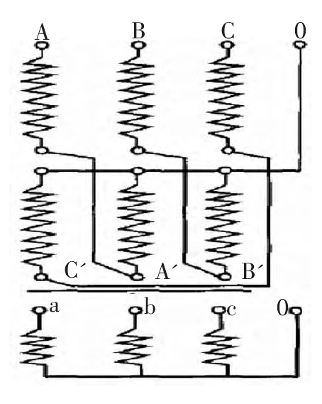
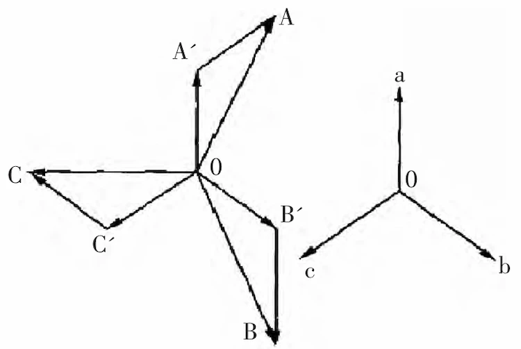
The main winding of the Neutral Grounding Transformer generally adopts a zigzag connection (Zn connection), and one end of each phase winding is connected to a common point (neutral point). The phase of each part of the induced voltage on the same iron core is different, but the magnitude and phase of the zero-sequence current flowing through are basically the same, and the generated magnetic potentials cancel each other.
The connection of the Neutral Grounding Transformer connected by Znyn11 is shown in Figure 1, and the voltage phasor relationship of each winding is shown in Figure 2.
From the phasor relationship in Figure 2, it can be calculated that the half-winding voltage of the main winding of the grounding transformer is U/3, and the current flowing in the case of a single-phase grounding fault in the system is I0/3.
Therefore, the design principle of the transformer can refer to the three-winding transformer.
When the neutral point of the Neutral Grounding Transformer is connected to the arc suppression coil and the small resistance grounding method, the zero-sequence equivalent circuit of the grid single-phase grounding fault operation is the zero-sequence impedance of the grounding transformer and the neutral point load impedance of the Neutral Grounding Transformer in series, flowing through the neutral point the current I0 is:
I0=Un/(Z0+Z2) (1)
where I0—the current at the neutral point, A
Un—system phase voltage, V
Z0—zero-sequence impedance of the grounding transformer, Ω
Z2–grounding transformer neutral point load impedance, Ω
Since the zero-sequence impedance of the Neutral Grounding Transformer and the neutral point load impedance have both inductive and resistive components, equation (1) is a phasor relationship equation.
Corresponding to the short-circuit performance of the power transformer, the Transformer Grounding considers the short-circuit fault of the neutral point grounding of the grounding transformer when the single-phase grounding fault of the power grid operates, which is equivalent to directly adding the phase of the system at both ends of the zero-sequence impedance of the Earthing Transformerr.
The voltage is called the zero-sequence short-circuit of the grounding transformer. With reference to the short-circuit performance of the power transformer, the zero-sequence short-circuit performance of the Earthing Transformer is required to meet the corresponding requirements.
The zero-sequence short-circuit performance of the Transformer Grounding includes: Heat resistance and dynamic stability to withstand zero-sequence short-circuit.
Considering the actual application of the grounding transformer, when the neutral point of the grounding transformer is connected to the grounding method of the arc suppression coil, the current duration of the zero-sequence short-circuit resistance is 2s;
When the neutral point of the transformer is connected to the small resistance grounding method, the current duration of the resistance to heat resistance of the zero sequence short circuit is 10s.
In order to reduce the impact of the zero-sequence impedance of the grounding transformer on the performance of the supporting device, the smaller the zero-sequence impedance of the grounding transformer, the better.
In order to reduce the safety impact of the zero-sequence impedance of the Transformer Grounding on the grounding transformer, the larger the zero-sequence impedance of the grounding transformer, the better.
Under the premise that the transformer can withstand the heat resistance and dynamic stability of the zero-sequence short-circuit, its zero-sequence impedance needs to be optimized and determined.
The influence of the zero-sequence impedance of the grounding transformer on the performance of the supporting equipment is mainly manifested in the current output of the neutral point when the single-phase grounding fault of the power grid is running.
When the neutral point of the Earthing Transformer is connected to the grounding method of the arc suppression coil, due to the influence of the zero-sequence impedance of the grounding transformer, when the single-phase grounding fault of the power grid operates, the compensation current will decrease, thus affecting the compensation effect of the complete set of devices.
When the zero-sequence impedance of the transformer exceeds 10% of the impedance of the arc suppression coil, it will directly affect the arc suppression device’s functions of compensating arc suppression and suppressing overvoltage.
For example, when the rated current of the arc suppression coil is 10.5kV, the rated current of the arc suppression coil is 100A, and the zero-sequence impedance is 15Ω/phase, the inductive component of the compensation current during the operation of the single-phase metallic ground fault of the power grid is only about 95A.
When the neutral point of the Transformer Grounding is connected to the grounding method of small resistance, due to the influence of the zero-sequence impedance of the grounding transformer, when the power grid single-phase grounding fault is running, the neutral point current will decrease. When considered, the system cannot operate effectively, which directly affects the safe operation of the small resistance grounding device and the power grid.
For example: 10.5k V, rated current of small resistance is 400A, and zero-sequence impedance is 15Ω/phase, the zero-sequence current in single-phase metallic grounding fault operation of power grid is only about 300A.
It is easy to cause the zero-sequence current relay protection of the system to not act, causing grid faults.
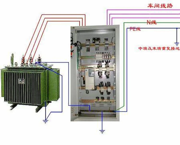
Grounding transformers often have a secondary (low voltage) winding to power local auxiliary loads, such as substation 400V equipment.
At this time, the high and low voltage capacity of the Earthing Transformer is different, especially when the low voltage capacity and the high voltage capacity are very different, it is often difficult to meet the requirements of the short-circuit impedance of the power transformer, and it can only be as close as possible, and the transformer must be guaranteed in the design. Meet the heat resistance and dynamic stability ability to withstand three-phase short circuit.
The design parameters of the Transformer Grounding mainly include: rated voltage, rated capacity, neutral point current and time, zero-sequence impedance and short-circuit impedance with secondary.
The method for determining the rated capacity and zero-sequence impedance of the grounding transformer is mainly analyzed here.
The high-voltage rated capacity S1 of the Transformer Grounding is mainly composed of the neutral point current capacity S2 obtained from the rated neutral point current and the rated secondary capacity S2, and is marked as S1/S2.
For the Earthing Transformer without secondary winding, S2=0, the rated capacity can be recorded as S1.
Generally, refer to the following formula for selection.
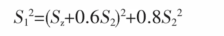
Among them, S1 and S2 are the primary capacity and secondary capacity of the grounding transformer respectively; S2 is the rated capacity of the neutral point load;
The power factor of the secondary load of the grounding transformer is taken as 0.8.
The neutral point load of the transformer is mostly short-time load. When the neutral point of the Earthing Transformer is connected to the grounding method of the arc suppression coil, it is generally 2h, and when the neutral point of the grounding transformer is connected to the small resistance grounding method, it is generally 10s.
According to the stipulation of overload factor made by the IEEE-C62.92.3 standard, the short-term capacity of the Transformer Grounding is converted to the continuous rated capacity, and its conversion is listed in Table 1.
| Overload time | Overload factor |
| 10s | 10.5 |
| 60s | 4.7 |
| 10min | 2.6 |
| 30 min | 1.9 |
| 2h | 1.4 |
Considering the above factors, referring to Figure 1 and Figure 2, when the neutral point of the Earthing Transformer is connected to the grounding method of the arc suppression coil, the current flowing through the neutral point of the Transformer Grounding (when the operating time is 2h) is converted into the continuous rated capacity:
Sz=(U/3×I0/3)×3/1.4
When the neutral point of the transformer is connected to the grounding method of small resistance, the current flowing through the neutral point of the grounding transformer (when the running time is 10s) is converted into the continuous rated capacity:
Sz=(U/3×I0/3)×3/10.5
In the formula, Sz—the continuous rated capacity converted from the neutral point load of the grounding transformer, kVA
U—system rated voltage, kV
I0—Rated zero-sequence current flowing through the neutral point of the grounded transformer, A
The rated capacity calculated by converting the continuous rated capacity according to the zero-sequence load of the Earthing Transformer is the required minimum value, which can be appropriately enlarged in the design process considering factors such as temperature rise and cost.
The rated capacity S1 of the Transformer Grounding without secondary winding is the continuous rated capacity Sz converted from the zero-sequence load of the grounding transformer.
The three-phase zero-sequence impedance of the transformer is generally taken as 2%~5% of the neutral point impedance, and when converted to single-phase, it is generally taken as 6%~15% of the neutral point impedance.
For example, the minimum rated capacity of the Earthing Transformer with 10.5k V, neutral point current of 100A, running time of 2h and secondary winding of 100kVA can be selected as 315/100kVA, and the zero sequence impedance can be selected as 3Ω/phase~9Ω/phase.
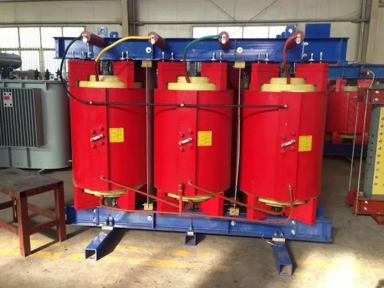
The following takes the design of a dry-type 10.5k V, neutral point current 100A, running time of 2h, and a Earthing Transformer with a 100kVA secondary winding as an example to briefly introduce the design process.
Rated voltage: 10.5/0.4kV
Rated capacity: 315/100kVA
Neutral point current and time: 100A, 2h
Connection group: Znyn11
Zero sequence impedance: 4.5Ω/
Phase short-circuit impedance: 4%
The iron core adopts a three-phase five-stage stepping circular section structure, the low-voltage winding is a two-layer cylindrical type, and the upper end enters and exits the wire. Lead out to panel terminals.
According to the formula for calculating the short-circuit impedance of the transformer, the inductive reactance part of the zero-sequence impedance of the Transformer Grounding is calculated as follows.
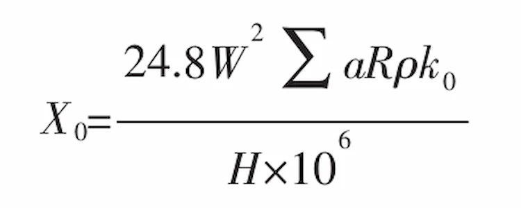
in the formula
X0—Zero-sequence impedance of grounding transformer, Ω/phase
W—the number of turns of the half winding of the transformer
Σa R—Equivalent leakage reactance area between half windings of grounding transformer, cm2
ρ—Rockwell coefficient
H—zero sequence impedance height, cm
k0—transverse flux leakage coefficient
The reason for introducing the transverse flux leakage coefficient is that there is a lateral flux leakage problem due to the difference in reactance heights of the high-voltage inner and outer windings. The magnitude of the transverse flux leakage coefficient k0 is related to the reactance height difference between the inner and outer windings.
The short-circuit impedance of the transformer is calculated according to the short-circuit impedance of the three-winding transformer.
First, calculate the short-circuit impedance Ux12, Ux13 and Ux23 between the high-voltage inner winding to the low-voltage winding, the high-voltage outer winding to the low-voltage winding and the high-voltage inner and outer windings, and the inductive reactance of the short-circuit impedance. The part is:
Ux=Ux12/2+Ux13/2-Ux23/6
The performance assessment of the Earthing Transformer is divided according to the neutral point load.
When the neutral point is connected to the arc suppression coil, it should meet the rated long-term load (with secondary winding), the rated neutral point current 2h temperature rise requirements, and should meet the zero sequence Heat resistance and dynamic stability of short circuit 2s;
When the neutral point is connected to a small resistance, it should meet the heat resistance and dynamic stability of the rated neutral point current for 10s under the condition of rated long-term load (with secondary winding), and should meet the heat resistance and zero-sequence short circuit for 2s. Dynamic stability.
The comparison between the technical parameters and experimental values of the grounding transformer with a dry-type 10.5k V, a neutral point current of 100A, a running time of 2h, and a secondary winding of 100kVA is shown in Table 2.
| Zero-sequence impedance (Ω.phase-1) | Short circuit impedance/% | |
| Calculated | 4.5 | 3.98 |
| Experimental value | 4.68 | 3.82 |
| error% | 4 | -4.02 |
The performance of the Transformer Grounding directly affects the performance of the supporting equipment and the safety of the power grid. In the design of this type of product, the calculation of zero-sequence impedance and short-circuit impedance must be considered.
On the premise of ensuring the temperature rise of the Earthing Transformer and the heat resistance and dynamic stability of the three-phase short circuit, the heat resistance and dynamic stability of the zero-sequence short circuit must also be satisfied.
Download Resource
Table of Contents Selecting the right pad-mounted transformer requires careful consideration of several critical

The primary function of the pad mounted transformer is to serve as a critical distribution

A pad mounted transformer operates through electromagnetic induction, serving as a crucial distribution component that
After filling in the contact information, you can download the PDF.