
How to Choose Pad Mounted Transformer?
Table of Contents Selecting the right pad-mounted transformer requires careful consideration of several critical
ELECTRIC, WITH AN EDGE
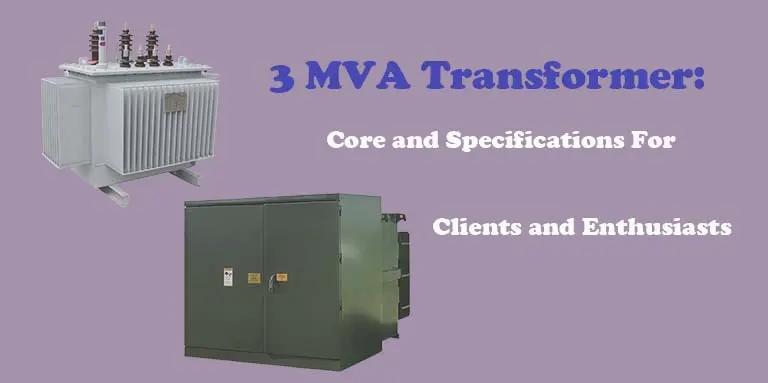
A 3MVA transformer is a static electrical appliance that transfers AC power by transforming AC voltage and current between two or more windings at the same frequency by means of electromagnetic induction.
Transformers are generally divided into two categories: power transformers and special transformers. Power transformers can be divided into generator transformers, transmission transformers, tie transformers and distribution transformers.
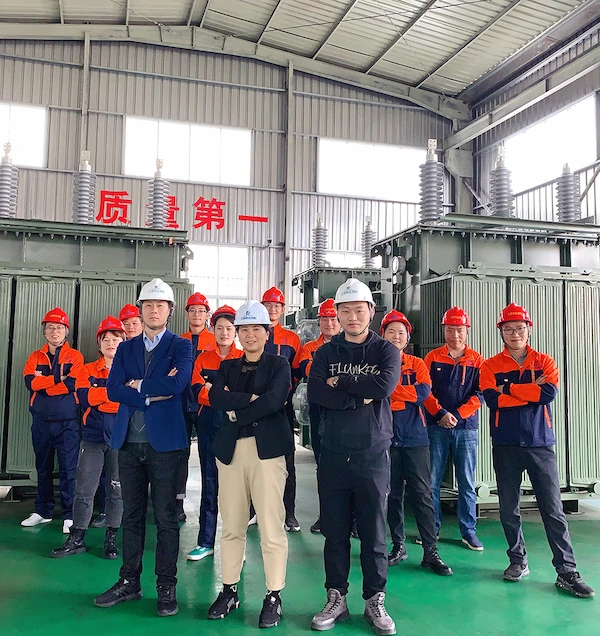
As a transformer factory that has been producing and designing transformers for more than 16 years, Daelim can not only provide you with the most customized services, but also provide you with transformers that meet industry experimental standards such as CSA, IEEE, and NISA. Having these transformers can help you reduce grid losses and bring you more economic benefits.
The apparent power in megavolt amperes (MVA) in 3 MVA Transformer is measured.
An electrical circuit’s perceived power is the sum of its current and voltage.
For purposes of describing overall electrical power in installations, this phrase is often used instead of “rated power,” which only considers actual, usable power.
Transformers and generators are among the most popular electrical installations to employ this rating.
In addition, there are additional derivatives used to derive 3 MVA transformers, such as kilowatt-ampere (kVa).
A megawatt ampere is the same as a thousand kilowatt amperes.
Engineers always consider the substation’s capacity while installing power generators and transformers in an electric power substation, so they install generators and transformers with comparable 3 MVA Transformer power capacities.
A substation’s 3 MVA Transformer power capacity can be used to estimate an industry’s or a neighborhood’s electrical power needs, which are then compared to that capacity.
Hence, MVA ratings for power transformers vary widely for every transformer.
Power transformers are evaluated by engineers to see if they are suitable for transferring power from the substation to businesses and residences.
3 MVA Transformer power capacity should be matched to the substation to minimize power loss.
As a result, power surges that cause property damage or even death are reduced because of better power management.
The 3 mva transformer is the main electrical equipment of the transmission and distribution system and the heart of the power supply.
The 3 mva transformer can also reduce the voltage to meet the needs of users. It is necessary to establish primary and secondary substations in the areas where electricity is used, and use transmission transformers to reduce the transmitted high-voltage power to a suitable voltage or connect to other power grids by tie transformes 3mva.
Finally, the power is sent directly to the user with a 3 mva transformer.
(l) Choose a 3 mva transformer, which can not only meet the needs of electricity consumption, but also make reasonable use of the capacity. It is not only necessary to not overload at high loads, but also to keep the load factor above 0.3.
(2) Before purchasing a 3 mva transformer, the statistical analysis of the load must be done well. The total number of kilowatts of electrical equipment, including irrigation and drainage, threshing, processing of agricultural and sideline products, and domestic electricity (including lighting, home appliances), how many kilowatts of the largest electric motor, and the power development plan in the past two or three years, etc., according to this to determine the number and capacity of 3 mva transformers.
(3) When choosing the capacity and number of 3 mva transformers, try to use multiple small-capacity distributions, avoid single large-capacity, and do not prefer large or small, so as not to cause the power supply range to be too large, and the power radius of low-voltage lines to be too long. Increase investment in line construction, resulting in excessive low-voltage line losses, operating costs and long-term high rural electricity prices.
(4) According to the current industry and national environmental protection policy requirements, energy-saving products must be selected, and SL, (S7) or S must be selected. series of low loss transformers. The low-loss transformer 3mva has new equipment, good technology, small self-loss and outstanding energy-saving effect. Compared with the old model SJ, the new sL; 10 kV 50 kV distribution transformer reduces no-load loss by 56.8% and load loss by 13.2%.
(5) According to the nature of the load and electricity requirements, set up a special 3 mva transformer. For example, special transformers for water conservancy can be set up for deep well water pumping and irrigation. Large-scale flour processing, machine brick production, and township industrial factories and mines all need to set up special transformers 3mva to meet the needs of production.
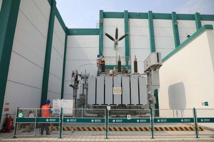
For 3 mva distribution transformers, high-voltage rooms and relay protection devices should be used.
The installation features of the 3 mva transformer are as follows: drop fuses are installed on the high-voltage outdoor inlet pole, and valve-type arresters are installed on the high-voltage outdoor wall inlet frame, and the high-voltage line enters the indoor high-voltage switch cabinet through the wall bushing.
There are oil-less circuit breakers and isolation knife switches in the switch cabinet, and two sets of current transformers are installed, one is connected to the measuring instrument, the other is connected to the relay protection device, and the protection device has overload, current quick-break and over-current protection.
When the 3mva transformer is overloaded, the overload relay will act and send out a signal: when a short circuit accident occurs inside the transformer 3mva, bushings, and leads, the current quick-break protection will act immediately, the switch will trip, and the transformer will be out of operation. The quick-break protection is the main protection of the transformer 3mva.
The overcurrent protection of the 3mva transformer mainly protects the overcurrent caused by the external short circuit of the transformer. It is the backup protection for the fault of the 3mva transformer. The overcurrent protection setting must be greater than the maximum load current, generally 1.5 times to 2 times the high voltage rated current. .
For 3 mva transformers, in order to reduce investment, AC operation is generally used, the trip coil is powered by current transformers, CS:-114 operating mechanism is used, and GL-15 (16) inverse time current relay is used for protection, which operates in the operating mechanism The two current trip coils of the circuit breaker trip. room
The 3 mva transformer can also be installed outdoors. Its overcurrent protection is mainly a multi-oil circuit breaker on the column, which has many models.
The current setting value is set by the setting screw in the operating mechanism box, and the setting screw is engraved with the operating current value. After adjustment, check the correctness of its setting value through the actual trip test.
Because the oil-on-column circuit breaker (oil-on-column switch) does not have an obvious air gap, in order to ensure safety at work, a set of high-voltage drop fuses must be installed.
For overcurrent protection on the high voltage side of a 3 mva transformer, only drop fuses are installed. The installation height should be easy to operate on the ground.
Generally, the distance to the ground should not be less than 4 meters, the height from the 3 mva transformer should not be less than 1.8 meters, and the horizontal distance between phases should not be less than 1.8 meters. .5 meters.
The rated current of the fuse fuse is selected according to 1.5 to 2.5 times the rated current of the high-voltage side of the distribution transformer.
When the rated current of the fuse is calculated, the closest one should be selected according to the specification of the fuse.
Taking into account the mechanical strength of the fuse, its current rating should not be less than 3 amperes.
In order to facilitate the user to select the fuse of the 3 mva transformer,
The basic principle of the transformer is the principle of electromagnetic induction. It consists of two windings and a core.
When the primary winding AX with the number of turns N1 is connected to the AC power supply with the frequency f and the voltage U1, a small excitation current I0 is enough to generate the main magnetic flux Φ0 (maximum value Φm) in the iron core and pass through the outside of the iron core. The leakage flux Φs and Φ0 of the loop induce potentials E1 and E2 in the primary and secondary windings respectively, and there is a voltage U2 at the ax end of the secondary winding.
When the secondary winding is connected with a load, the secondary winding will flow current I2, and the primary current will increase from the excitation current I0 to I1 when there is no load.
Under no-load operating conditions,
If the magnetizing potential, the resistances r1 and r2 of the primary and secondary windings and the reactances x1 and x2 due to the leakage flux are ignored.
The voltage ratio of the primary and secondary windings U11U2 is equal to the number of turns N11N2.
N2 remains unchanged, the larger N1 is, or the N1 remains unchanged, the smaller N2 is,
Then U2 is smaller; N2 is unchanged, N1 is smaller or N1 is unchanged, N2 is larger, then U2 is larger.
Obviously, the purpose of changing the voltage can be achieved by changing the number of turns in either of the two windings. Usually, a number of taps (tap) are drawn on a certain winding to change the turns ratio N11N2, thereby changing the secondary voltage value. This is why a transformer 3mva can change the voltage.
When the secondary winding is connected to the load and the current flows, the secondary magnetic potential (current × number of turns) must cancel the primary magnetic potential because the excitation magnetic potential is ignored. To maintain balance, the larger the secondary current, the larger the primary current.
The current transformation relationship is the opposite of the voltage transformation relationship. As the voltage ratio expands, the current ratio shrinks. This is why a transformer 3mva can also change the current.
Everything you need to get the job done will be included in the equipment you’re purchasing 2500 kVa Transformer in Daelim.
Regardless of whether or not they are explicitly stated in the commercial order, such parts are considered to be included in the supply.
However, it is not the intention to provide exhaustive information on the design and building process.
Quality, durability, and long-term serviceability are required by law for the equipment that is offered by Daelim.
Materials will be designed and constructed according to good engineering practice in accordance with the required product quality and any tolerances, allowances, and clearance requirements etc. required by various stipulations in Daelim Standards, IEC standard, etc. in these specifications despite any anomalies, discrepancies, omissions, incompleteness, etc.
In accordance with Daelim Rules, transformers should be suitable for outdoor installation with the following system specifics and should be able to operate under supply voltage fluctuations.
All applicable laws, regulations, and safety codes must be met in the design, manufacture, and performance of the equipment.
This specification in no way absolves the bidder of his responsibilities.
According to IS 1180 (Part 1) and IS 2026, the maximum temperature rise for top oil over an ambient temperature of 50°C shall be 40°C that is measured by thermometer.
To comply, resistance method has a measurement in accordance with IS1180 IS 2026 should yield a maximum temperature rise for winding of 45° C over an ambient temperature of 50° C.
Note that when securing the core to the tie rod, spring washers must be utilized.
Therefore, the foundation and basis of the body 75 mm X 40 mm X 6 mm MSChannel with correct fastening is required to support the yoke.
Locking bolts will be used to secure the core assembly.
Moreover, all parts of the core and yoke must have maximum flux densities of less than 1.9Tesla at rated voltage and frequency.
At rated voltage and frequency, the flux density should not exceed 1.55 Tesla.
Limit of no-load current must not exceed 2% of the full load current of each winding at its rated voltage and only four HV coils per phase are allowed.
Daelim annealed steel lamination with low loss and good grain characteristics, coated in hot oil proof insulation, and fastened together to the frames to prevent vibration or noise shall be used as core material.
All of the core clamping bolts must be properly insulated before being used.
Continuous operation of the transformers requires that the entire core design ensure that the core losses are permanent.
Thus, high quality cold-rolled grain-oriented (C.R.G.O.) annealed steel lamination with low loss and good grain characteristics will be used for the core, which will be insulated with hot oil-proof coating.
Continual operation of the transformers necessitates a core design that prevents core losses.
When using CRGO material, the core material should not be fragile.
Reticular-shaped M.S. sheets of prime grade will be used to construct the 2500 kVa Transformer tank. This must be built to withstand the rigors of daily use.
There should be no bulging in the tank or fittings during service.
The design of the tank must allow the core and windings to be raised without restriction.
The tank plates must be strong enough to lift the entire transformer with the help of the lifting lugs when it is loaded with oil.
On the same note, the interior of the tank must be varnished or painted with oil-resistant paint.
In order to prevent water from entering the cover plate gasket, the top cover plate should be slightly sloping; roughly 5 to 10 degrees towards the HV bushing. The minimum bend plate width is 25 mm.
At the lifting lug point, the top cover shall be uncut.
The corners of the rectangular tank will be welded together during construction.
Corrugated transformer tanks are also permissible, although the tank’s shape must only be rectangular.
Minimum 1.6mm corrugated sheet thickness is required.
Cooling will be accomplished through the use of corrugated panels.
The transformer must be able to deliver its rated output continuously without overheating beyond the limits stated.
The offer must be accompanied by a complete computation sheet.
For the tank’s corrugated side, a 50X50X5 mm safe guardangle structure must be welded in place.
In connection, horizontal or vertical joints in tank walls and its bottom or top cover are not permitted in rectangular tanks.
There should also be an opening in the main tank’s cover for the escape of trapped air.
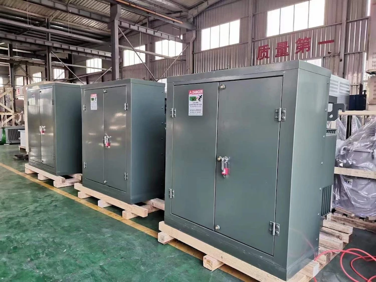
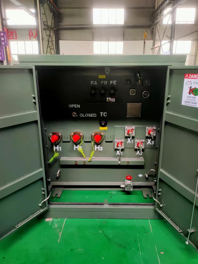
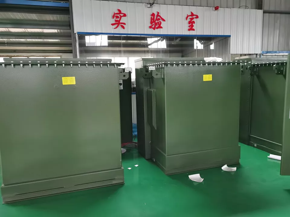
Utility, commercial, and industrial facilities can all benefit from the flexibility and ruggedness of Daelim series three-phase pad-mounted transformers.
These transformers, which are both energy efficient and safe, can be placed either outside or inside structures.
They come in a wide range of layouts and a number of accessories to fulfill both the most basic and the most complicated of requirements for fluid-filled transformers.
•Live-front or dead-front compartments are both options for this compartment.
•Special attention was paid to surge prevention in the design of this critical load
•With a focus on surge protection, this data center is built to withstand the most extreme electrical conditions.
•For GSU (Solar Photovoltaic Generator) applications, Solar is specifically designed.
•Combined with either transformer or loop overcurrent protection, the vacuum fault interrupter saves space and money.
•For more adaptability and cost savings, they can be placed near or inside structures.
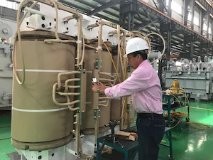
Vacuum processing of the core and coil is required to guarantee that the insulating fluid gets as far into the coil insulation system as possible ensured by Daelim.
The transformer will be loaded with preheated filtered degassed insulating fluid and the windings will be powered up to heat the coils and drive away moisture while under vacuum.
In order to avoid gaps in the corner joints, the core must be made of burr-free, grain-oriented silicon steel and stacked correctly.
Other options include low-loss amorphous metal and/or the best core material based on the given loads and/or assessment equations.
Insulating the coil with B-stage, epoxy-coated, diamond pattern, insulating paper that is thermally cured under pressure ensures good bonding between the conductor and paper is required.
Aluminum or copper coils can be used to remove the need of a certain metal.
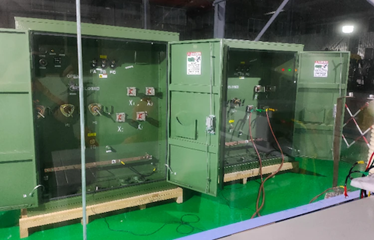
Moreover, there should be a metal barrier separating the high-voltage and low-voltage compartments on the same side of the transformer.
If you’re facing the vehicle, you’ll see the low-voltage storage container on the right side.
The door to the high-voltage compartment must be constructed so that it can only be opened once the door to the low-voltage compartment is opened.
Before attempting to open the high-voltage door, one or more additional fastening devices must be removed.
Flat panel doors with a three-point latching system and a handle for a locking device are required for low-voltage compartment doors.
3 MVA Transformer has 1.3 Wb/m 2 at any tap position with a voltage change of less than 10% from the tap voltage is permitted.
High-quality cold-rolled grain-oriented silicon steel should be used for the laminated core.
The tank will be welded together and constructed using low-carbon steel that has been thoroughly tested.
An internal pressure of 0.35 kg/sq. cm over the typical hydrostatic pressure of oil must be designed into it.
Rainwater should not collect on the tank lids, which should be sloping.
Hence, a weatherproof hot oil resistant neoprene gasket should be used between all fastened connections to ensure total oil tightness.
Submission of a pressure test calculation is required.
Wheels with dual-direction axles, jacking pads (four), and lifting lugs are required.
For safety, hot-dip galvanized, cadmium-plated, or zinc passivated steel nuts and bolts exposed to the weather are required.
In accordance, the transformer’s overall dimensions should not exceed 3700 x 2700 x 3100 mm (H). There should be no more than 3700 square feet of floor space.
The 2700mm side of the transformer should have the HT and LT terminals installed.
There are no fractional measurements.
3 MVA Transformer has NEMA TR –126 specifies maximum and minimum limits.
Fresh insulating oil should be as per IS 335, without an inhibitor, before it is poured into the transformer.
Non-returnable containers containing 10 percent more oil will be provided in sealed barrels for topping.
On the other hand, for XLPE cable termination with Daelim Type heat shrinkable termination kits, HT and LT sides are acceptable. H.T., L.T., and marshaling boxes will be supplied with 4mm thick aluminum blank gland plates.
Porcelain bushings conforming to IS 2099 and IS 3347. For both H.V. and L.T. side cable boxes, the distance between the cable gland plate and the cable lug must be at least 550 millimeters.
IS 2026 specifies the requirements for terminal marking.
The use of epoxy bushings is not permitted.
Threaded or Plug type terminals are acceptable.
The cost of each type of test must be specified separately in the price quote.
Nevertheless, the technical offer must contain an affirmation to that effect.
The Technical offer must include an unpriced copy of the pricing bid.
Orders placed with a supplier should be followed up with a design submission for approval, which should include calculations to ensure the transformer is suitable for inverter duty.
For dispatch clearance, the transformer must be examined by Daelim engineers.
All temperature indicators, Daelim relays, and other auxiliary devices must be able to handle 220 volts dc.
For 220 V circuits, all of the alarm and trip contacts must be able to be used.
A power supply is not included in the package.
For instance, nylon, stainless steel, or cadmium-plated nuts and bolts should be used on outside surfaces that will be subjected to the elements. 2.5 mm stranded copper wire, rated at 1100 volts, will be used for the control wiring.
The transformer will be shipped with all of the necessary cable glands and lugs already attached.
Cable glands will be nickel plated brass with twofold compression.
Cable lugs will be attached to the cable box using fixing hardware.
The 3 MVA Transformer will be subjected to the following evaluations:
•Routine examinations in accordance with the most recent IS 2026 Magnetic Balance Test issue or modifications.
•The transformer will be subjected to the following tests.
•Test for temperature increase in accordance with IS2026 and its most recent revisions.
•HV and LV windings are tested for full wave impulse and voltage peaks must meet the requirements of IS 202
Download Resource
Table of Contents Selecting the right pad-mounted transformer requires careful consideration of several critical

The primary function of the pad mounted transformer is to serve as a critical distribution

A pad mounted transformer operates through electromagnetic induction, serving as a crucial distribution component that
After filling in the contact information, you can download the PDF.