ELECTRIC, WITH AN EDGE
In the actual design process of distribution transformers, reasonable design and selection of transformers are required.
On this basis, it can be ensured that the transformer can better meet the actual needs, so as to ensure that the distribution transformer can be better used, and its role and function can be better played.
Therefore, relevant staff should pay attention to the design and selection of distribution transformers.
Reasonable design and selection should be made to promote better application and development of distribution transformers.
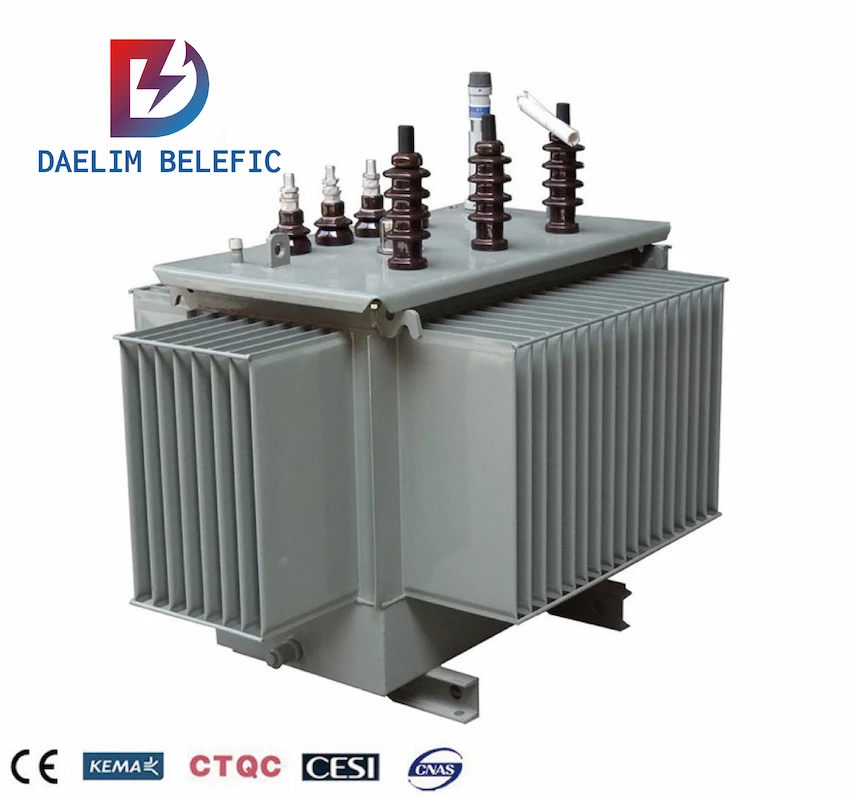
Daelim is a transformer manufacturer engaged in R&D, production, sales and installation and commissioning services of power transmission and distribution and control equipment. It has more than 15 years of professional production experience in power distribution equipment. We can design and produce professional transformer equipment according to your requirements.
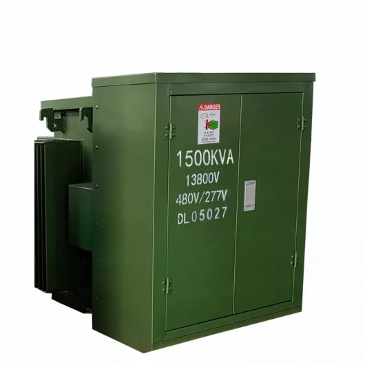
The main products are dry-type transformers, pad mounted transformers, S9, S11 series fully sealed transformers, high ignition point oil transformers, single-phase transformers, combined transformers, pre-installed substations and cable junction boxes.
Daelim’s sales network covers the United States, Canada, Venezuela, Egypt, Germany and other countries. The distribution transformers produced by Daelim can perfectly fit the power equipment requirements of your market.
Daelim has passed IEEE 60076.CSA, ANSI C57.12.00, IEC60076,, and SGS, and has a number of national patents.
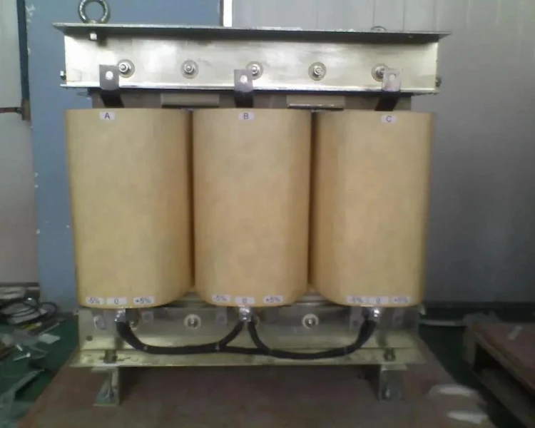
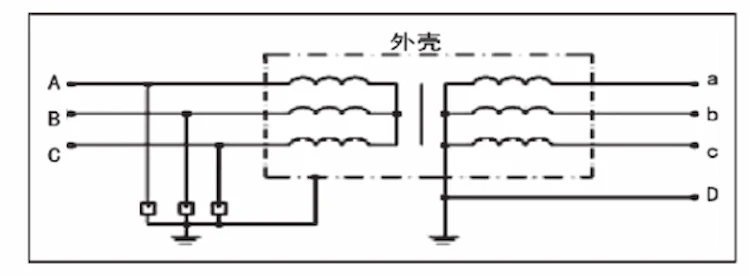
Distribution transformers belong to a category of power transformers. They use electromagnetic induction as their working principle. The related schematic diagram is shown in the following figure. The two sides are high-voltage windings and low-voltage windings. The primary winding is connected to the power source, and the secondary winding is connected to the load.
The number of turns of the primary winding is W1, and the number of turns of the secondary winding is W2, and there is no electrical connection between the two windings, only magnetic coupling.
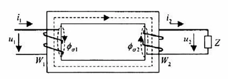
From the above figure, it can be found that it is precisely because of the principle of electromagnetic induction in the working process of the distribution transformer, that is, the phenomenon that magnetism is generated through inductance, and electricity is generated by magnetic induction. When winding 1 is connected to alternating voltage u1 At the same time, a sudden current will be generated, and in the process, the current flowing in the core will generate alternating magnetic flux at the same frequency as the power supply voltage.
The electric energy transfer of different voltage levels in the distribution transformer is the induced electric potential generated by the winding voltage at the same frequency, and the alternating current generated by the combination of the induction TV with the same frequency in the group 2.
There are two main aspects that affect the loss of distribution transformers, one is active power loss, and the other is reactive power loss.
In the actual operating process of distribution transformers, the loss generated is called active loss, which can be divided into copper loss and iron loss in more detail.
The specific manifestation is the occurrence of iron core heating in the distribution transformer.
Most of the loss of this function is dissipated in the form of heat. If it is serious, it will also have a certain impact on the operation of the distribution transformer.
Carrying out a detailed analysis of the loss, then the iron loss includes the two major aspects of hysteresis loss and eddy current loss.
Eddy current loss refers to the fact that in the specific working process of the distribution back pressure device, because its own magnetic field lines exist in the iron core, it triggers the principle of electromagnetic induction in the distribution transformer, so that the current will form a closed loop in the coil. Circuit, resulting in vortex-like rotation.
At the same time, since the iron core in the distribution transformer will generate eddy current flow, the iron core in the distribution transformer will emit a certain amount of heat, thereby consuming the energy of the distribution transformer.
This part of the energy consumption is called This is the eddy current loss.
For the hysteresis loss in the distribution transformer, it means that when the AC current passes, the size and direction of the magnetic field lines passing through the rigid sheet of the distribution transformer show regular changes, and then there will be mutual friction, and then
This causes the distribution transformer to generate thermal energy, and this part of the thermal energy loss is called the loss of magnetic mass.
Copper loss is not very common in distribution transformers.
It mainly refers to the loss in the coil resistance of the distribution transformer.
The specific manifestation is that when the current in the distribution transformer passes through the coil resistance, it will be generated due to heat dissipation. Energy, this process will convert part of the electrical energy into heat, which is then consumed.
For distribution transformers, the loss generated in the transformation and energy transfer is called reactive power loss. This process is due to the fact that there is no actual active power in the distribution transformer.
The reactive power loss in the distribution transformer is also divided into two parts. First, the current of the distribution transformer itself may have a certain connection with the load current, which constitutes non-constant loss.
Moreover, if the load current in the distribution transformer is larger, the loss it generates will be larger.
On the other hand, because the distribution transformer is built on the current connected to the main magnetic circuit, the constant loss that occurs thereafter is not directly related to the load current in the distribution transformer.
When designing the distribution transformer, the relevant staff do not need to consider the particularly large capacity, but only need to design the capacity to meet the actual reactive power loss.
For distribution transformers, oxygen-free copper can be used in the process of circuit design, and oxygen-free copper can be used as a oriented material.
Its advantages can help the distribution transformer to reduce the internal resistance of the coil. By adopting this method, the iron loss and copper loss in the distribution transformer will be reduced, so as to help the distribution transformer to achieve a loss-saving situation.
The high-temperature superconducting voltage distribution device that has been put into use at present has adopted superconducting wire, which improves the short-circuit performance of the distribution backpressure device, and also helps it achieve the effect of reducing loss.
If distribution transformers want to save energy and reduce operating losses, the magnet materials in the distribution transformers must be upgraded.
In recent years, distribution transformers have begun to use amorphous alloy materials to help distribution transformers achieve demagnetization functions and have achieved reliable results.
If you start with the manufacturing process of distribution transformers, you can also achieve the purpose of energy saving and loss reduction.
For example: The currently commonly used CNC machining systems are mostly controlled by computers, which is convenient for designers to process the silicon steel sheets inside the transformer.
The thickness, interface shape and other parameters of the silicon steel sheets can be precisely controlled, which greatly reduces the operation of distribution transformers.
According to relevant data, the current processing accuracy of silicon steel sheet has reached 0.18mm.
Related research currently focuses on two aspects, one is the use of a new type of winding structure, and the other is the use of a new type of coil arrangement.
The former is considering that the traditional winding structure has poor anti-harmonic interference capability and excessive loss. Different winding structures can be selected according to the different grades of the distribution transformer itself.
For example, through the use of self-adhesive transposed conductors, it is possible to achieve all aspects of control of the leakage bucket image of the distribution transformer, thereby helping the distribution transformer to reduce the loss that may occur in the windings. This way, it can improve the power distribution The benefits of the transformer itself can also ensure safe operation.
Compared with the former, the latter is mainly based on the flow direction of the eddy current, and then choose the horizontal or vertical method to realize the arrangement of the coils in the distribution transformer, so as to reduce the degree of loss in the operation of the distribution transformer.
In the implementation process of distribution transformers, to improve the economic operation mode, we must pay attention to the selection of materials and processes of distribution transformers.
Compared with the original traditional transformer, by adopting the method of reactive power compensation, it can help the distribution transformer to achieve the purpose of energy saving.
The path for distribution transformers to implement reactive power compensation mainly includes the following aspects.
The first is the centralized compensation of reactive voltage transformers, that is, the installation of parallel capacitors in distribution transformers into high and low voltage distribution lines.
The second is the group compensation of distribution transformers. The so-called group compensation is to install the parallel compensation capacitors in the distribution transformers into the distribution transformers, the low-voltage side and the power distribution panel of the user workshop.
By adopting the above methods, the energy-saving level of distribution transformers can be better improved, and the transmission power of distribution transformers can be enhanced.
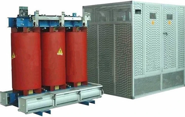
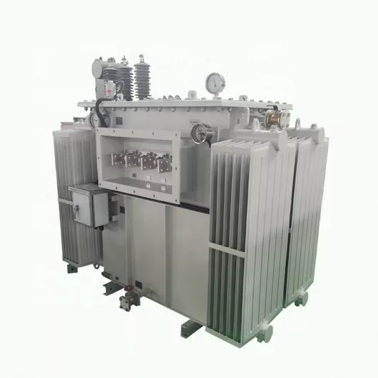
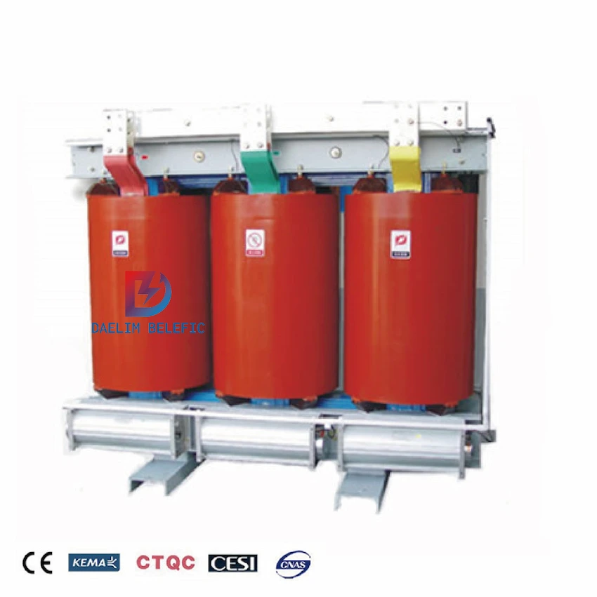
In the process of designing and selecting distribution transformers, transformer type selection is a very important content. At present, the more commonly used transformers mainly include two types, namely dry-type transformers and oil-immersed transformers.
As far as the current actual situation is concerned, the practical application of dry-type transformers is becoming more and more extensive, and the models included are mainly SC(B)7, SC(B)8, SC(B)9, SC(B)10, etc.
Among these models, SC(B)10 is a new product, which has obvious advantages in intelligent environmental protection and energy saving.
In addition, in the actual application process, dry-type transformers can save 33% no-load loss, and can save 15% load loss, and have the advantage of lower noise, and have strong super-nameplate performance.
In some specific cases, the load capacity can be improved, so that it can reach about 1.5 times the rated capacity.
Compared with oil-immersed transformers, dry-type transformers have the advantages of oil-free and low noise, and the floor space can be greatly reduced, the installation steps are relatively simple, the reliability is relatively high, and the maintenance is relatively convenient.
However, this type of transformer also has certain shortcomings, mainly in that the capacity is relatively limited, and the cost is relatively high, and the penetration rate is lower than that of oil-immersed transformers.
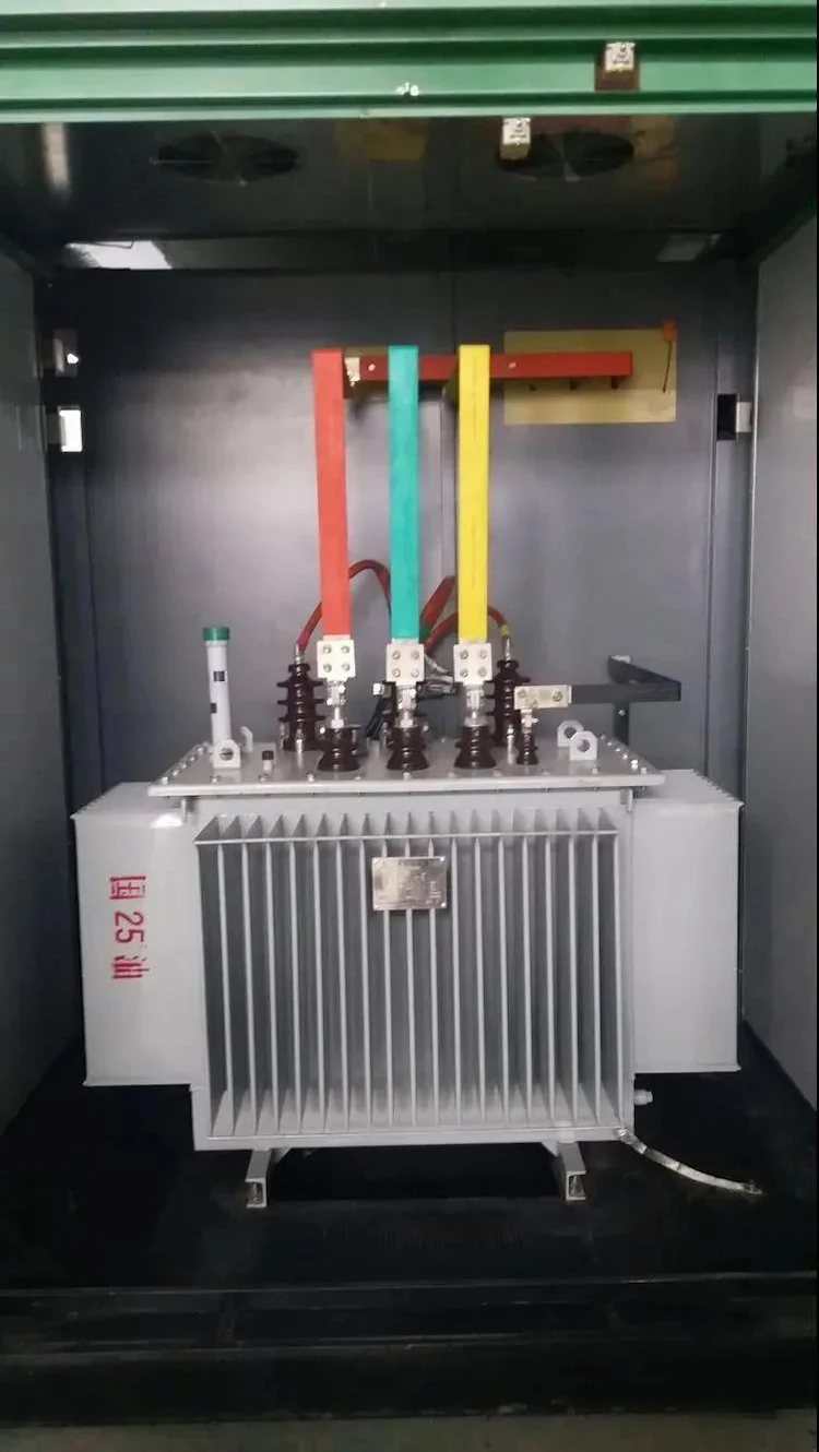
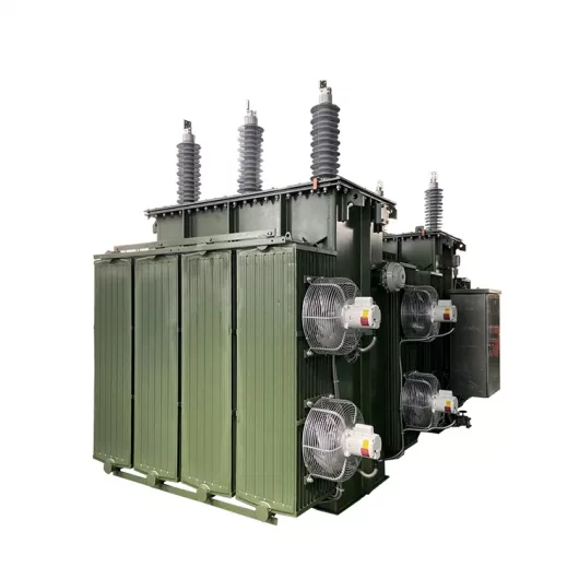
In the current transformer market, oil-immersed transformers still occupy a dominant position. Their models mainly include S7, S9 and S11. Among them, S9 and S11 are more widely used, especially S11, which should be very extensive.
The main purpose is to utilize the design experience of 10kV transformers. Under the load capacity of 1600kV·A, and there is no obvious impact on the load, it has a wide range of applications, and has the characteristics of economy and reliability.
In the process of transformer type selection, it is usually necessary to follow certain rules, that is, SC(B)10 dry-type transformers can be selected when conditions permit, and S11 wound core transformers can be selected if economic conditions are not ideal. Some aspects have specific requirements and needs, and a new type of fully sealed S9 core transformer can be selected to meet the actual needs.
In the process of design and selection of distribution transformers, the selection of transformer capacity is the basic work.
In the process of transformer capacity selection, the basic basis is the specific load nature and load situation.
A reasonable analysis of the current user development should be carried out, and its long-term planning should be carried out.
Make reasonable predictions and implement a comprehensive configuration of transformers.
As far as the current actual situation is concerned, the most commonly used method in the selection of transformer capacity is the least total cost method, and the total cost of the transformer refers to the entire process of using the transformer.
The economic cost of investment in the transformer and the economic cost related to the loss, in the selection of transformer capacity, through the application of this method, can ensure that more ideal economic benefits can be obtained.
Specifically, the overall cost of the transformer mainly includes three aspects, namely, the cost of purchasing the transformer, the cost of no-load loss, and the cost of load loss.
Factors affecting no-load loss costs and load loss costs mainly include electricity prices, financial conditions, and related large-scale projects.
In the design and selection of distribution transformers, the connection group of distribution transformers is also a very important aspect.
As far as the current distribution transformer connection group is concerned, it mainly includes two forms, namely Yyn0Dyn11. In the actual application process, the Dyn11 connection group is selected as much as possible. The reasons are mainly reflected in the following two aspects.
First of all, choosing the Dyn11 connection group method is more beneficial to suppress the relevant high-order harmonic currents appearing on the load side, and can effectively avoid waveform distortion, so that the power quality can be guaranteed.
As far as the current practical application is concerned, the double-turn variable method is usually selected in the distribution transformer.
When the applied voltage outside the primary side appears as a sine wave, its electric potential and magnetic flux usually also appear as a sine wave, but due to the core saturation factor Influence, the no-load current appears as a spike wave, which includes not only the fundamental wave, but also higher harmonics, especially for the second harmonic, which has a relatively large amplitude.
At this time, if the distribution transformer chooses the Dyn11 connection group mode, for the high-order harmonic current in the excitation current, if the primary side is connected to a digon, a circulating current can be formed on the primary side, and the excitation current will also behave as Peak wave, and the primary side potential and excitation flux are all shown as a sine wave, and the related secondary side induced electric potential is also shown as a sine wave.
Thereby, the secondary harmonic potential of the secondary side can be better suppressed, and there is no second harmonic current in the load current so that the waveform distortion of the load current can be effectively avoided so that the quality of the power supply waveform can be better guaranteed.
Secondly, choosing the Dyn11 connection group method can make full use of the transformer equipment capacity, so that the transformer output can be used to the greatest extent.
According to the relevant standards, in some low-voltage power grids, when the Yyn0 connection group three-phase transformer is selected, the neutral line current caused by the single-phase unbalanced conformity should be controlled within 25% of the rated current of the low-voltage winding.
And the one-phase current should be controlled within the rated current value when it is a full load.
For the above standards, clearly limits the single-phase compliance capacity in the case of Yyn0 connection, which also restricts the use of Yyn0 connection methods, which leads to insufficient utilization of the transformer equipment capacity.
When the Dyn11 connection method is selected, it does not limit the current in the neutral line and can reach the line current of the low-voltage side of the transformer, so that the transformer capacity can be fully utilized so that the equipment capabilities can be fully utilized, especially It is especially suitable for transformers with single-phase load as the mainstay and two-phase unbalance.
Therefore, in the selection and design process, for some new distribution transformers, no matter which type of transformer is selected, the Dyn11 connection group should be selected, so that its role and functions can be fully utilized and better-performed application.
Oil-immersed distribution transformers are cheap and have a low loss (such as S11 and amorphous alloy transformers).
The key components are all sealed in transformer oil.
They have good insulation and cooling effects and strong adaptability.
They are widely used in distribution networks.
The disadvantages are:
Dry-type distribution transformer occupies a small area and can be arranged in the same room with SF6 circuit breakers and vacuum switchgear. It has strong anti-overload ability, good flame retardant performance, high optional temperature resistance grade, strong short-circuit resistance ability, maintenance-free, and in power transformation. It is widely used.
The disadvantages are:
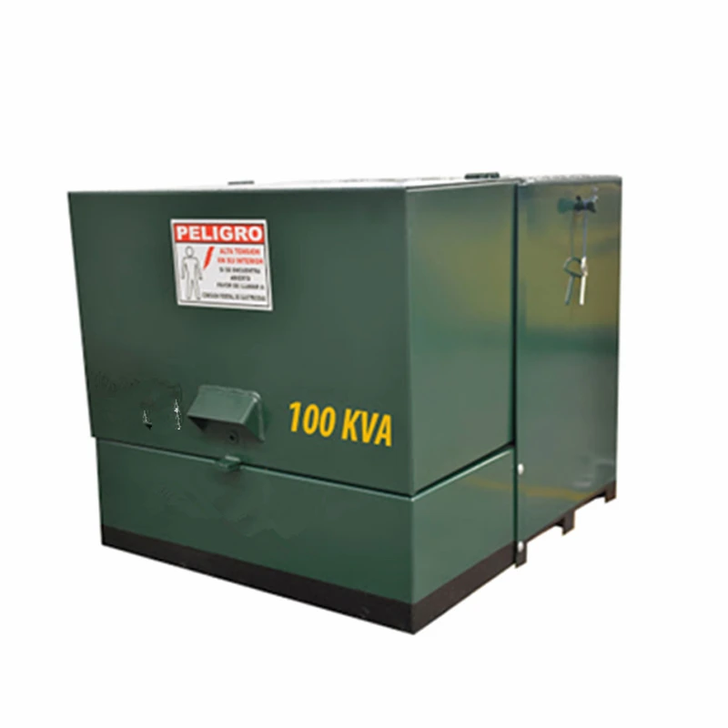
According to its characteristics, design specifications, and operating experience, oil immersed distribution transformers are mainly suitable for pole erection, pad-mounted substations, and distribution rooms and substations with separate distribution transformer rooms;
Dry-type distribution transformers are mainly used for indoor power distribution.

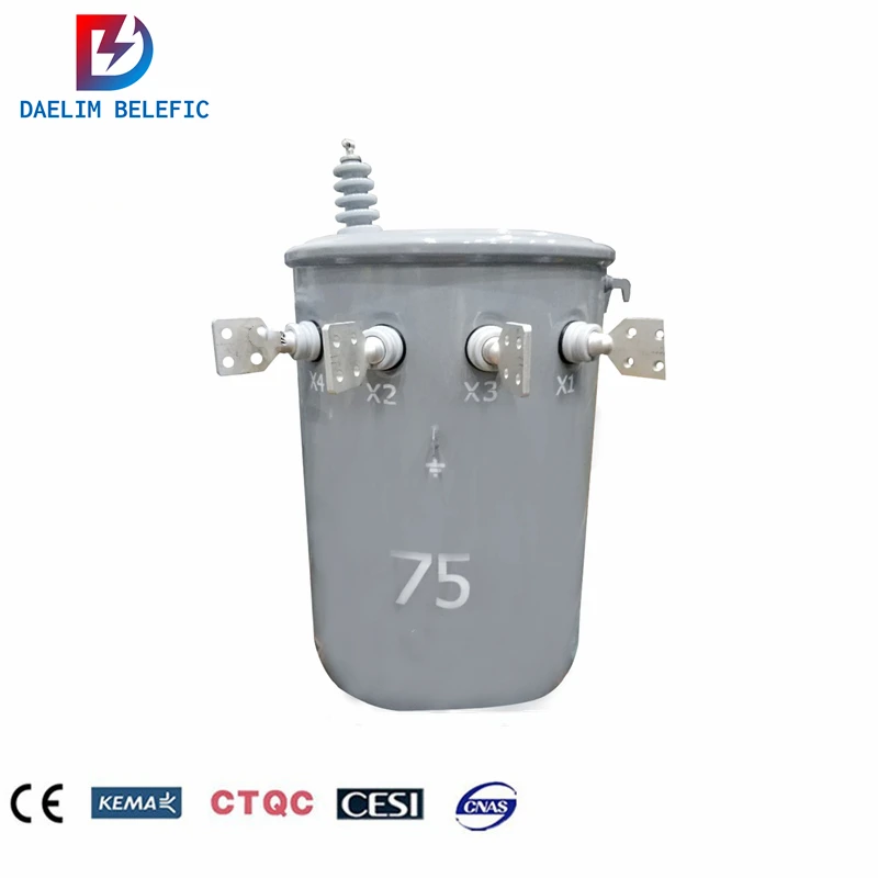
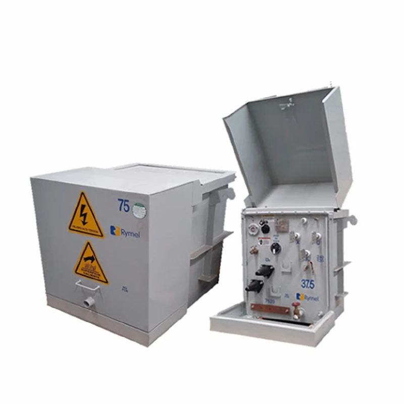
Single-phase distribution transformers are small in size and can be erected on a single pole, making it easy to go deep into the load center for power supply;
The single-phase distribution transformer itself has low loss, and because it can supply power close to the residential side, it greatly reduces the loss of low-voltage lines;
Since the single-phase distribution transformer has 3 outgoing wires (different from the three-phase four-wire), the investment cost of the low-voltage line is saved.
Therefore, single-phase distribution transformers conform to the guiding ideology of small-capacity densely distributed points, and have been widely used in distribution networks in recent years, mainly in urban residential areas, villa areas, street lights, and small rural areas where relatively concentrated residential areas are located.
However, due to the small capacity of single-phase distribution transformers and only single-phase output, it cannot be used rationally and economically in areas where small power is scattered and in urban multi-storey and high-rise buildings.
The number of transformers should be selected according to load characteristics and economic operation.
When one of the following conditions is met, two or more transformers should be installed:
For a substation equipped with two or more main transformers, when one is disconnected, the capacity of the remaining transformers should meet the power consumption of the primary load and the secondary load.
The capacity of the remaining transformers should not be less than 60% of the total load.
When constructing a 10kV substation, two or more distribution transformers should be installed.
When the substation is located inside the building, and there are special requirements for fire and explosion protection, or the area is too small to set up a separate distribution transformer room, dry-type distribution transformers should be used.
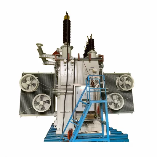
When selecting dry-type distribution transformers, the cooling method adopts natural air circulation and forced air circulation (with a cooling fan).
Under normal conditions of use and natural air cooling, the distribution transformer can continuously output 100% of the rated capacity.
Putting in the fan and running under forced air cooling, the distribution transformer can continuously output 150% of the rated capacity.
When choosing a dry-type distribution transformer, the capacity of the main transformer of the substation can be selected according to the scheme of high load rate.
When there are 2 main transformers (N=2), the load rate is 65% (T=65%), and the low-voltage adopts single-bus section connection mode;
When there are 3 main transformers (N=3), the load factor is 87% (T=87%), and the low voltage adopts single bus four-section wiring.
When a box-type substation is selected, or when the substation is set independently, a separate distribution transformer room can be set up.
When there are no special requirements for fire and explosion protection, oil-immersed transformers (S11 type of amorphous alloy transformers) can be used.
Oil-immersed distribution transformers are selected, which are low in price and have a relatively low no-load loss, but their overload capacity is poor. When selecting the capacity of the main transformer, it can be selected according to the scheme of low load rate.
When there are 2 main transformers (N=2), the load rate is taken as 50% (T=50%), and the low voltage adopts single-bus section wiring mode;
When there are 3 main transformers (N=3), the load factor is 67% (T=67%), and the low voltage adopts single bus four-section wiring.
For the selection of a single distribution transformer in a line or substation, it should also be based on load characteristics and the characteristics of existing low-loss distribution transformers, combined with load growth, through calculations and economic and technical comparisons (considering investment in capacity expansion, new placement The actual difficulty), the economic operation of the distribution transformer can be ensured at the lowest load, and the selection of a distribution transformer with a larger capacity level is also conducive to safe, reliable and economic operation.
Technical indicators of grounding resistance value The safety of distribution transformer installations is closely related to the grounding resistance. Its resistance includes two parts: the stray resistance of the grounding body and the resistance of the grounding device. To ensure the safety of the grounding device of the distribution transformer, it must be effective for its grounding resistance. Control and strict specifications.
(1) Due to the different application environments of distribution transformers, the soil resistivity of the environment is also different. The soil in different environments is quite different. Generally, the resistivity of the soil is in the range of 5-5000Ω/m.
Therefore, soil resistivity is a very critical index in the value of grounding resistance, and determining soil resistivity is also the primary task.
(2) Then there is the connection problem between the circuit breaker, the main power distribution device and the ground wire.
In order to ensure safety and avoid accidents, there must be more than 2 grounding wires connected to the high-voltage circuit breaker and power distribution.
At the same time, the area of the grounding surface should be fully considered and scientifically adjusted to ensure the normal operation of the final grounding device of the distribution transformer.
In the connection of the power distribution main transformer and the power distribution device, a reasonable setting is made based on the orientation of the grounding grid, and finally the voltage between the external structure of the device and the grounding body is ensured to be constant.
During construction, scientific installation methods must be used to ensure that the grounding device meets the operational requirements of the distribution transformer.
In addition, in the actual application process of the grounding device of the distribution transformer, it is necessary to fully consider its operation, and conduct regular inspections on the operation and service life to ensure that the grounding device can ensure stable operation during the operation and commissioning period.
In the construction of the grounding device of the distribution transformer, chemical corrosion methods are used to deal with the external rust problem after the welding of hot-dip galvanizing. In order to further improve the safety and reliability of the operation of the grounding device of the distribution transformer, the dipping method or the soil transfer method is generally introduced to meet the requirements for the use of the grounding device.
In the installation of the grounding device, the topographical conditions and hydrological elements must be fully considered, and the scientific installation method must be selected in combination with the operating conditions of the distribution transformer.
Galvanized flat steel and round steel have good applicability in the current grounding devices of distribution transformers.
They should be installed horizontally in a trench with a depth of about 0.6m to ensure that there is a distance of about 2.5m between the ground.
If the vertical installation method is adopted, a buried depth of >2.5m is generally required, and the distance is more than doubled through multi-level connection.
The safe construction of the grounding device should be one of the key contents of the installation of the grounding device of the distribution transformer, which directly affects and determines the safe operation of the distribution transformer.
The previous analysis has pointed out that the resistance of the grounding device is the key factor affecting its safety.
Therefore, while hydrology and soil conditions are considered in the resistance selection of grounding devices, relevant standards should also be paid attention to, and base materials should be strictly selected on the basis of standards.
If a vertical grounding body is used, a 2.5 m galvanized angle steel can generally be used, and a cross-sectional area of 50mm*50mm*5mm can be guaranteed.
Ground resistance | 1 | 4 | 10 | 15 | 20 |
N1 | 30 | 3 | 2 | 1 | 1 |
N2 |
| 10 | 4 | 3 | 2 |
Table 1 shows the selection criteria for the number of vertical grounding bodies, indicating that the selection of the number of vertical grounding bodies must meet the specifications.
In addition, for the horizontal grounding body, galvanized flat steel is generally selected as the material, and the cross-sectional area is 50mm*6mm.
To ensure the effectiveness of grounding protection, the smoothness and uniformity of the cross-section of the galvanized flat steel should also be ensured.
When selecting a grounding device for a distribution transformer, it is necessary to comprehensively consider the operating conditions, grounding conditions, and grounding protection requirements of the distribution transformer to ensure that it meets the common grounding protection requirements of the main transformer and high-voltage power distribution equipment.
In addition, the possible repeated grounding in low-voltage power distribution equipment should be fully considered, and safe points (usually two) should be selected reasonably in the neutral connection trunk line and the ground trunk line to ensure the connection between the grounding body and the safety point.
In the installation of the grounding device, the trunk line and the branch line should be connected to effectively avoid the problem of circuit series.
In the installation of the grounding device of the distribution transformer and related equipment, the technicians fully analyze the parts that need to be grounded, and set the corresponding round steel or galvanized flat steel (50mm*5mm) according to different needs, which effectively guarantees the connection of the metal conductor of the grounding body Safe operability.
For the grounding protection of the main transformer of the distribution transformer, it is necessary to ensure that there are> 2 grounding wires connected to the main transformer, and the grounding grid position must be considered when connecting.
The scientific connection is based on the position.
The iron core and shell in the transformer Can effectively reduce its pressure-bearing value, and the application of multiple grounding wires also effectively relieves the pressure equalization of the grounding body.
For the grounding wire connected between the middle grounding grid and the high-voltage circuit breaker, more than 2 grounding wires must be used.
To ensure safety, the cross-sectional area of the grounding body must be effectively extended.
At the same time, this method effectively reduces the ground wire breakage and avoids poor contact. , The line is aging, and the relay protection refuses to operate.
The previous analysis pointed out that the difference in the soil directly affects the safety of the grounding device.
Generally, the resistivity of the area where the grounding device is installed should below.
The main reason is that the soil resistivity is positively related to the grounding resistance of the grounding device.
When the grounding device is installed, the smaller the soil resistivity in the installation environment, the smaller the grounding resistance will be.
In order to ensure the safety of distribution transformers, not only the application environment should be considered during installation, but also the installation location should be considered from the perspective of grounding safety.
When it is as close to the load center as possible, choose an area with a relatively low resistivity for the grounding device installation.
The professional level and professional quality of the staff involved in the installation of the grounding device directly determines the operating level of the grounding device.
Therefore, there are clear requirements for the professional quality of the relevant staff.
They must continuously improve their professional and technical level and ensure that they have a high sense of responsibility and dedication.
Do the grounding installation work conscientiously and at a high level.
The previous analysis pointed out that the grounding resistance directly affects the effectiveness of the operation and application of the grounding device.
Therefore, the grounding resistance must be selected on the basis of scientific analysis to ensure that the grounding resistance is within a reasonable range to ensure the stable operation of the distribution transformer and stable power supply.
If the grounding wire is broken and the resistance increases or the grounding resistance itself is large, the abnormal power supply voltage may occur, which will eventually affect the burning of distribution transformers and other related equipment, so we must pay attention to it.
The installation of the actual grounding device and the determination of the grounding resistance are based on the capacity of the distribution transformer.
If angle steel or steel pipe is used to lay the grounding device, vertical grounding or vertical arrangement is generally adopted to ensure sufficient spacing between different grounding bodies.
Generally, the spacing should be greater than twice the length of the grounding body.
At the same time, the wiring part of the grounding body should also be used. Carry out anti-mechanical damage and anti-corrosion treatment.
For a grounding wire, different electrical equipment cannot be connected in series for grounding at the same time to avoid potential safety hazards.
The grounding body that has been laid must be processed after the construction is completed, and backfilled and compacted in layers.
After the grounding device of the distribution transformer is installed, it cannot be put into operation directly.
It is necessary to conduct reasonable tests on the established plan and installation device to verify the economy, safety and environmental protection of the grounding device.
Special attention should be paid to its safety and to ensure the grounding of the installation. The device can meet the actual grounding protection requirements.
If the safety of the grounding device does not meet the actual needs, problem analysis and improvement are needed.
The article pointed out that the application of single-point grounding in grounding devices has great disadvantages, which can no longer meet the requirements of current distribution transformer operation safety. Dual grounding has become an important development direction for the installation of grounding devices in the future.
In the actual installation of the actual grounding device, in addition to the determination of the grounding method and the grounding point, the actual application environment and the operation requirements of the distribution transformer should also be fully satisfied.
This article puts forward two installation schemes of grounding devices based on the operation of electric power enterprises, and analyzes and discusses these two scheme cases.
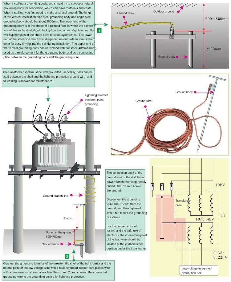
The grounding device installation schematic diagram based on Option 1 is shown in Figure 1. The grounding device is installed by introducing the neutral point and the distribution transformer shell connection. The lightning protection device, as another key device in the distribution transformer, must be installed separately. When the arrester is working (discharging), there will be a discharge residual voltage. This residual voltage needs to be borne by the high-voltage coil in the distribution transformer. In addition, the voltage drop of the grounding resistance also needs to be borne by the high-voltage coil, and finally transmitted to the low-voltage side by induction.
When the neutral point and the housing of the distribution transformer are grounded, the voltage difference in the high-voltage coil increases rapidly, which may cause the distribution transformer to be overloaded and eventually cause it to be burned.
The previous analysis pointed out that there will be a residual voltage when the arrester is discharged, and the final discharge residual voltage is borne by the high-voltage coil, and the induced voltage on the low-voltage side also needs to be stressed by it.
In order to improve the existing defects and problems of the solution, it is necessary to improve the installation of the distribution transformer grounding device. On the basis of the neutral point grounding of the distribution transformer, the distribution transformer and the shell of the lightning rod are connected and grounded. The specific installation diagram is shown in Figure 2.
If the schematic diagram shown in Figure 2 is used to install the grounding device, the residual voltage generated by the discharge of the arrester is also borne by the high-voltage coil, and it also bears part of the grounding resistance voltage drop. In addition, the low-voltage side can also share part of the voltage in this process through induction.
However, in this scheme, the distribution transformer and the arrester shell are connected to the ground, and the low-voltage side neutral point is separately grounded, which can ensure that the low-voltage side induced lightning can be effectively introduced into the ground.
quality of the staff. At the same time, after the installation of the grounding device is completed, scientific and necessary tests are required to determine the final application of the aversion.
In addition, when the grounding device is put into operation, it is necessary to fully grasp the operation status of the grounding device, conduct regular maintenance, find and solve problems in time, and ensure the safe operation of the power distribution line.
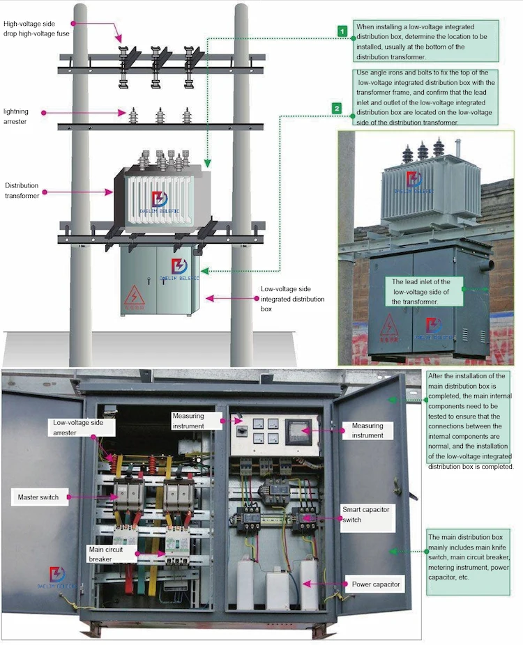
Distribution transformers, drop-out high-voltage fuses, lightning arresters, grounding devices, etc. constitute the power supply part of the temporary power system on the construction site, and need to be installed and connected during installation.
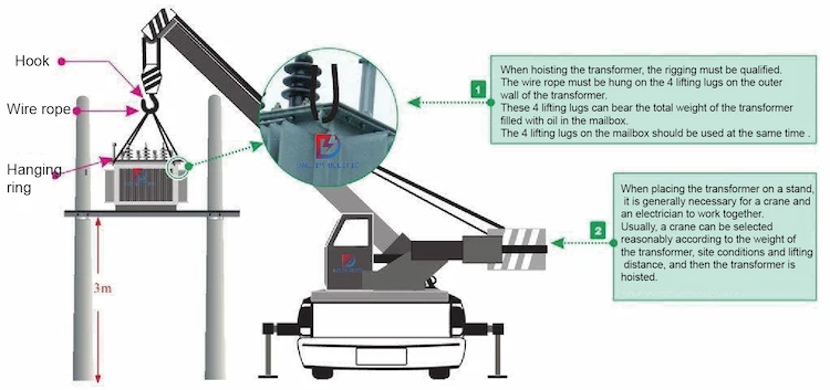
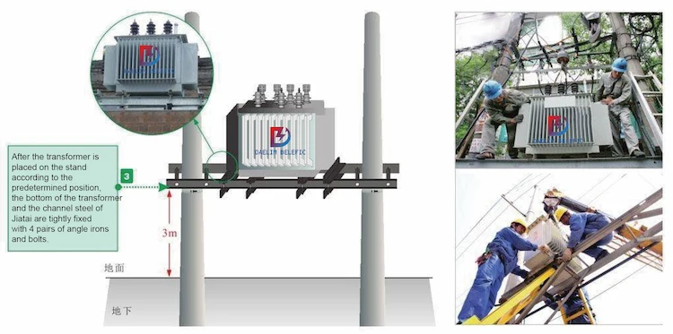
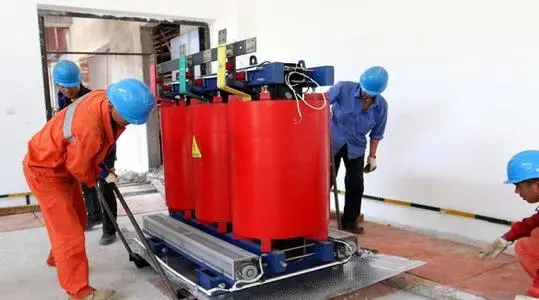
The distribution transformer needs to be installed on the stand of the pole.
During installation, it is usually lifted with the help of a crane, placed on the stand, and fixed.
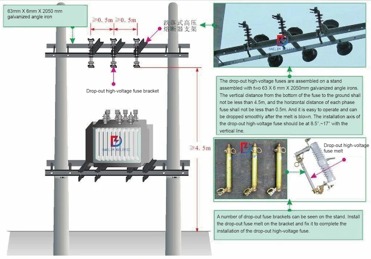
The drop-out high-voltage fuse is mainly composed of an insulating bracket, fuse melt, etc., installed on the high-voltage side of a distribution transformer or on the line that is delivered to the branch, and has the functions of short-circuit protection, overload, and circuit isolation.
Installation of drop-out high-voltage fuse
It is worth noting that the melt of the drop-out high-voltage fuse is selected according to the principle that it can be quickly fused when a short circuit occurs in the distribution transformer or the high and low voltage outlets.
The fusing time of the melt must be less than or equal to 0.1s. Generally, when the capacity of the distribution transformer is 100kVA and below, the melt rated current of the drop-out high-voltage fuse is selected as 2 to 3 times the rated current of the high-voltage side of the transformer; when the transformer capacity is more than 100kVA, the melt of the drop-out high-voltage fuse.
The rated current is selected by 1.5 to 2 times of the rated current on the high voltage side of the transformer.
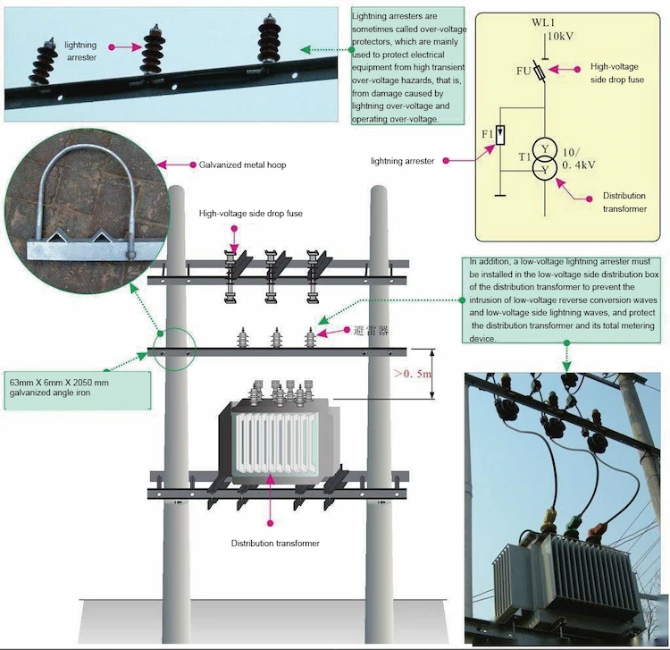
Lightning arrester is an indispensable lightning protection device in distribution transformers.
Generally, the high-voltage side arrester should be installed between the high-voltage fuse and the transformer, usually on a 63mm×6mm×2050mm galvanized metal cross arm.
The grounding device is mainly composed of a grounding body and a grounding wire.
Generally, the metal conductor directly in contact with the soil is called the grounding body; the metal conductor connected between the electrical equipment and the grounding wire is called the grounding wire.
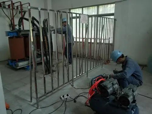
The installation of the grounding device includes the installation of the grounding body and the installation of the grounding wire.
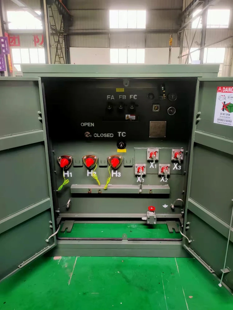
The main distribution box is mainly used for the connection with the output side of the distribution transformer.
It is usually a unified low-voltage integrated stainless steel distribution box, which is generally installed under the distribution transformer stand.
After the distribution transformers, related power distribution devices, and general distribution boxes are installed, you need to connect these devices with wires of corresponding specifications.
Before wiring the distribution transformer and related equipment, you need to connect the arresters in pairs, and then connect to the lead of the grounding device.
The connecting wires between the arresters are usually multi-strand copper-core plastic wires with a cross-sectional area of not less than 25mm2.
After the wiring between the arresters is completed, it is necessary to connect the high-voltage down conductor with the drop-out fuse, arrester, distribution transformer and main distribution box according to the power supply relationship.
The picture shows the wiring of the distribution transformer and related equipment.
Before carrying out the operation and maintenance of distribution transformers, it is first necessary to formulate a more reasonable and scientific plan, and in the actual maintenance work, follow the provisions of the maintenance plan for maintenance work, so that the guiding role of the maintenance plan can be fully exerted.
In addition, regular, rigorous and precise inspection and maintenance of distribution transformers are required to avoid operational failures caused by the aging of distribution transformers.
Under normal circumstances, the wear and aging of distribution transformers are more prominent, and regular inspection and maintenance work can promptly occur the aging phenomenon, and take corresponding measures to deal with it to minimize the occurrence of power failures.
The formulation of a maintenance plan can guide the development of maintenance work.
Therefore, the maintenance staff of electric power companies need to investigate and study the actual working conditions of distribution transformers, allocate the maintenance personnel of the distribution transformers reasonably, and do a good job in the maintenance of the distribution transformers to ensure the normal operation of the transmission work.
The internal components of the distribution transformer bear high load for a long time, which causes the operation of the transformer to always remain in the load state, which in turn leads to the failure of the distribution transformer components.
In order to ensure the stable operation of the distribution transformer, various internal components need to be maintained and processed to ensure that the components of the distribution transformer maintain normal working conditions.
There are many electrical components inside the distribution transformer, and there are various types, and there is a certain degree of complexity and difficulty in the actual maintenance process.
Therefore, in the process of processing distribution transformer components, it is necessary to first study the leakage problem of the distribution transformer joints to ensure the tightness of the distribution transformer.
In addition, the position of the seam needs to be inspected more strictly, and the seam position needs to be cleaned up.
Oil pillows can be used to deal with the oxidation and aging problems of distribution transformer components, and special attention should be paid to the sealing treatment.
In the process of refueling the distribution transformer, it is necessary to control the refueling speed to ensure that the refueling speed is kept within a reasonable range as much as possible.
Distribution transformers have higher requirements for the working environment.
In the process of high-load power transmission, the current will lose the distribution transformer.
The loss of the distribution transformer has a certain impact on the voltage stability, which has a certain impact on the user.
The electricity consumption situation brings different degrees of impact.
Therefore, in the maintenance work of distribution transformers, it is also necessary to strengthen the treatment of the loss of the distribution transformer, and take different measures according to the degree of loss of the transformer.
If there is only a slight loss of the distribution transformer, the maintenance personnel can deal with the loss accordingly.
On the contrary, the loss is more serious, and the maintenance personnel need to replace the parts in time to ensure the normal operation of the distribution transformer.
The loss of distribution transformers is relatively serious.
When purchasing, you can choose a distribution transformer with a relatively high cost performance to effectively reduce the failure of the distribution transformer.
The distribution transformer will emit a continuous and uniform sound during normal operation.
If the distribution transformer has intermittent sound during operation, or the humming sound from time to time indicates the abnormal operation of the transformer, this fault is mainly caused by the vibration of the magnetic core during the operation of the distribution transformer.
In the actual maintenance work, if the transformer has uneven sound, the maintenance personnel can distinguish the approximate fault of the distribution transformer according to the sound state.
The uneven sound lasts for a long time, which may be caused by excessive current, excessive power of the equipment, and The system has a fault caused by a short circuit. In the later work, the maintenance personnel need to make a specific analysis of the distribution transformer fault based on the general judgment;
If the sound inside the distribution transformer continues to occur, it may be abnormal due to the vibration of the chip silicon steel sheet; maintenance personnel needs to continuously observe the operation status of the distribution transformer.
If the abnormal sound gradually becomes louder, the operation of the distribution transformer needs to be stopped in time;
If there is a strong, uneven abnormal sound, accompanied by explosion sound and discharge sound, it may be because the iron core thread is loose and the iron core body is loose, and the continuous vibration causes the silicon steel sheet insulation material to be damaged, and the iron core temperature gradually rises.
The electric discharge will also cause damage to the insulating material and even cause a fire.
When this kind of noise occurs, the maintenance personnel need to stop the operation of the distribution transformer in time, and conduct a detailed analysis of the cause of the fault.
During the operation of the distribution transformer, the damage of the iron core and the damage of the transformer coil will convert electric energy into heat.
The transformer coil and the iron core continue to heat up, which causes the temperature of the distribution transformer to gradually rise, which in turn causes the internal oil temperature of the transformer to rise.
The heat is being conducted to the radiator of the transformer.
Relevant regulations require that in order to avoid premature aging of the insulator, the temperature of the distribution transformer needs to be kept below 85 degrees Celsius.
When the load remains unchanged, the oil temperature of the distribution transformer exceeds the standard 10 degrees Celsius and continues to rise.
In the event of potential faults, the main reasons for the continuous increase in oil temperature are short circuits in the coil, poor heat dissipation of the radiator, or internal faults in the distribution transformer.
Tripping faults during the operation of distribution transformers are relatively common faults.
The specific manifestation is that the maintenance personnel should accurately judge the cause of the faults that trigger the tripping of the distribution transformers based on the protection actions.
When it is an electromagnetic structure, maintenance personnel should carefully inspect the spring structure and start power insurance.
When the trip switch is a hydraulic structure, maintenance personnel can judge the cause of the fault by checking the pressure of the trip switch.
In addition, maintenance personnel needs to detect the reasons for the tripping of the low-voltage side switch of the main transformer. When the low-voltage side switch of the main transformer trips, such as switch malfunction, bus trip failure, super trip failure, etc., the maintenance personnel need to check the low-voltage side of the main transformer. The switch performs protection operation inspection.
Before inspecting the fault, the maintenance personnel needs to have a sufficient understanding of the actual situation of the distribution transformer to minimize the maintenance risk.
The insulation of insulation faults directly determines the quality of distribution transformers.
Most transformer faults are caused by insulation faults.
When the quality of the insulating medium deteriorates, the distribution transformer oil in the liquid insulating medium will volatilize a large amount of water vapor.
The aging of the insulation medium causes leakage faults. Under normal circumstances, the insulation system can still continue to operate when it fails, but it will stop after a short period of operation.
The occurrence of insulation failure has a great relationship with the environment.
Under normal circumstances, the key components of distribution transformers are prone to failure during operation.
Therefore, when dealing with faults in the transformer core, you can first check the hoisting core.
After a detailed inspection, you can learn about the specific faults of the core. When it is determined that the core is indeed faulty, perform inspections on the damaged part of the core.
Paint, according to the actual situation of the iron core failure, use reasonable and scientific technology to paint the appropriate area.
After handling the fault, debug and run the distribution transformer to avoid accidents of the distribution transformer.
The troubleshooting method of the tap switch of the distribution transformer
Tap changer failure is one of the most common failures during the operation of distribution transformers.
The probability of tap changer failure is extremely high, which has a great impact on the safe operation of distribution transformers. The failure factors of tap changer exist in two aspects:
First, when the contact of the insulating plate at the tap changer is poor, or the welding quality of the tap changer does not meet the standard, it will also cause poor contact and cause a malfunction;
Secondly, the screws at the installation position of the tap changer were not tightened, resulting in malfunctions.
For the more serious problem of poor contact, the insulation board needs to be replaced; for the loose tap switch screw, just tighten the screw.
In most cases, when the distribution transformer is operating normally, the relay protector and the circuit breaker device will not have tripping problems. If a fault occurs, the distribution transformer protection device will take trip protection to control the fault in time and reduce the cause of failure.
In the event of a trip, maintenance personnel needs to stop the operation of the distribution transformer in time, report the actual trip to the dispatcher, carefully check the cause of the trip of the distribution transformer, restart the transformer, and observe the transformer Whether there are abnormal noises, short circuits, fires, etc. inside.
At the same time, after restarting the distribution transformer to automatically trip the fault, it is necessary to ensure that the distribution transformer is restored to operation under the premise that there are no other faults in the distribution transformer.
For uncertain conditions, operation is not allowed to avoid the distribution transformer from burning.
When the grounding installation of the distribution transformer is not standardized or unreasonable, it is prone to lightning faults.
At present, there are two main aspects of common poor grounding:
First, the lightning protection device of the transformer has a fault problem, which causes the resistance to rise;
Second, there is no lightning protection device installed on the low-voltage side of the distribution transformer. When lightning strikes the transformer, it will directly cause damage to the transformer.
In view of the above two problems, in the process of dealing with the problem of poor grounding, the relevant staff first need to measure the resistance of the grounding line and analyze the reasons for the increase in the resistance of the grounding line.
According to the actual situation, combined with the equipment requirements, Adjust the equipment, or re-arrange the cables, and install lightning protection devices.
In the actual operation process of the distribution transformer, in order to obtain a more ideal effect, it should be designed, and the design and selection of the distribution transformer is one of the more important aspects.
Make the distribution transformer more in line with actual needs, so that its role can be better played.
After filling in the contact information, you can download the PDF.