ELECTRIC, WITH AN EDGE
A 3 winding transformer is a highly distinct electrical mechanism from the usual winding electrical transformer setup. As the name suggests, the former has an additional winding or coil connected to the transformer core. It is known as the tertiary winding, considered as a secondary winding that transfers output voltage to the load.
Transformers with tertiary windings have multiple benefits to power distribution and safety. It prevents voltage imbalance and also provides power for other equipment and appliances within the substation. Lastly, it provides protection against short circuits in a delta circuit.
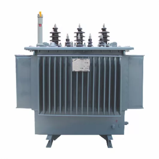
Fortunately, Jiangsu Daelim Electric Co. Ltd. offers single-phase 3 winding transformer setups for various electrical grids and transformer systems. Having 15 years of electrical equipment production, Daelim ensures that the products are of high quality. Safety is also guaranteed as Daelim meets international standards from ANSI, IEEE, CSA, and IEC.
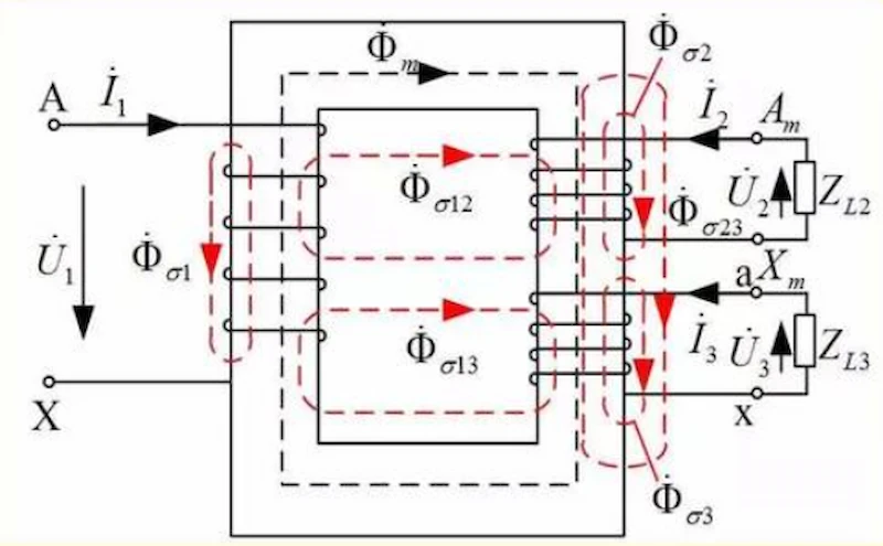
A single-phase 3 winding transformer is a different mechanism in transferring voltages from one coil to another. Much like the two-winding single-phase counterparts, the former operates with the same essential parts.
The primary winding, for instance, is where the input voltage comes from and is attached to the silicone steel-sheeted core. Then, the transformer core will then provide a way for the electricity to move in magnetic flux. Lastly, the secondary winding will carry the output voltage up to its destined load.
Additionally, both transformers can also operate as a step-up or step-down transformer. They work on the basic principle of “turns ratio.” It determines the input-output voltage rate depending on the number of “turns” on the coils of both windings. The turning frequency in one winding means that it has or requires more voltage rate than the other.
In this case, a step-up transformer will mean higher voltage output than input, with the second winding having more coil turns. Meanwhile, a step-down transformer has less voltage output as the first winding has more coil turns.
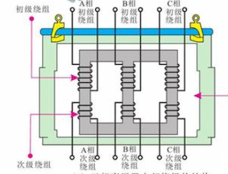
Nonetheless, three winding electrical transformers have a tertiary winding connected to the output side of the coil. The voltage rate from the primary (input) winding will split between the two remaining windings in this setup.
Depending on turns in each of the secondary coils, the amount of voltage is not evenly distributed in this mechanism. Thus, the secondary winding may have a voltage rate higher than that of the tertiary winding.
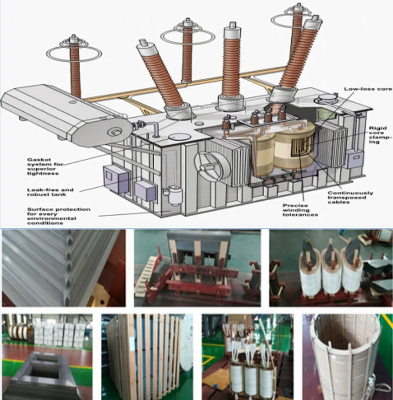
Three winding transformers operate the same as a typical single-phase electrical transformer with one primary and one secondary winding. In this case, the main difference between the two types of transformers is a tertiary winding in the former. Although, the functions of the third winding can slightly change depending on the connections within the transformer.
For instance, in a simple connection, a primary coil is attached to one core side. On the other side of the core, there are two secondary coils. The two secondary windings will share the input voltage from the power source and into the primary winding. The third winding, in this case, is a separate electricity line to another load with less voltage than the second winding,
In contrast, the structure of the third winding is different in a wye-wye connection. This one involves a third winding in a delta connection, with three coils attached in a triangular fashion.
Within a wye-wye transformer, the third winding provides a pathway for the balancing currents. The path is generated when the connection is not established from one series to the other. Rather, without such wiring connective pathways, it may result in output terminals having varied values.
Adding a tertiary winding provides another way for a balanced current to flow when unbalanced loads are on both sides. Adding a third coil is crucial. It allows voltage shifts and asymmetrical voltages, which would be very dangerous otherwise.
Nonetheless, in both setups, the number of turns in the coils is crucial. The “turns ratio” principle states that windings with more turns on the transformer core require a higher voltage rate. Thus, either of these setups is helpful in a step-up and step-down transformer system.
Single-phase two winding and three-winding transformers are different in the number of coils connected in the transformer. Nonetheless, each setup has additional features, functions, and benefits in generating and transferring power. Here are some critical distinctions between the two-winding and three-winding transformers.
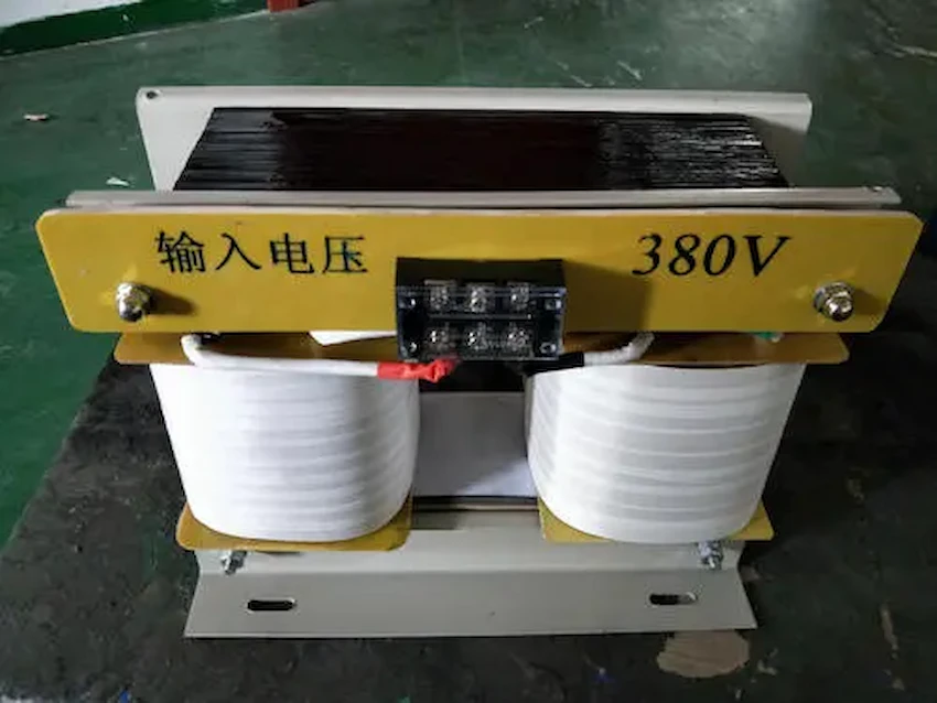
Two-winding transformers, also known as “double winding” transformers, are commonly referred to as the primary electrical transformer setup.
One of the essential features of this setup is using two isolated windings — the primary and the secondary coil. Input voltage from an electrical source will travel to the transformer through the primary winding. Meanwhile, the secondary winding will carry the output voltage to the load.
Each circuit includes a magnetic core that is laminated with the windings. As the circuits interact, they induce currents in each other, which can transfer electricity between them.
The amount of flux linkage varies depending on how linked together the primary and secondary windings are. It leads to greater efficiency by ensuring maximum transfer of power across both paths.
In a single-phase transformer, the arrangement between the parts of the transformer is usually simple. Yet, a three-phase transformer requires a series of connections with three sets of primary-secondary pairs.
Two winding transmitters have few faults due to the simplicity of the mechanism. It enables galvanic isolation that keeps both circuits separated from each other. Such systems also take advantage of magnetic coupling as the primary mode of energy transfer throughout the course.
In addition, places with varied environmental conditions have long used these transmitters to require power. With that, you can say that two-winding transmitters have been reliable for various power generating purposes.
Two-winding transformers are usually compared to autotransformers. Unlike windings that are electrically connected, windings in an autotransformer are magnetically attached, as well.
In this case, a single, common winding is tapped at various lengths to provide a portion of the primary voltage supply across its secondary load. It means that an autotransformer has less than half as many windings. Core space requirements for the transformer are reduced due to sharing between both circuits.
As a result of this, two-winding transformers are less favorable than autotransformers. Despite being a standard in industrial and commercial installations, autotransformers outperform them in terms of costs.
Due to an autotransformer’s mechanisms that require less copper for a given voltage rating, you can save up to an estimated 30 percent. Voltage regulation is also superior in autotransformers due to lower resistance and leakage reactance loss.
A three-winding transformer usually involves a third coil in a single-phase two-winding setup. It also has a three-coil delta connection in a wye-wye design. Either way, you should consider the polarities of the links when operating transformers with more than two windings.
You can add a third coil to the usual primary and secondary winding arrangement in a single-phase setup. It is imperative to pay attention when connecting the rings on a multiple winding transformer such as this setup.
Polarity matters, and connecting the two windings in reverse may lead to the transformer not functioning correctly. Thus, it would help to look into which dot convention mark represents positive or negative voltages for each coil.
Meanwhile, the tertiary winding is different in a wye-wye configuration. In this case, the first and second windings are connected in a Y-shaped arrangement. It means they share one common connection point, acting as the “neutral” charge for both windings. But, this setup is prone to have grounded or lose connection, also known as a “floating neutral.”
Additionally, high harmonics may lead to a decrease in iron and copper, affecting the voltage distribution. It is why a tertiary winding is inserted between the two wye connections.
Three winding transformer setups allow for transfers of electricity to numerous loads of varying voltage using one transformer. It also supports voltage transfers for additional equipment and appliances within the power station. It leads to more efficiency for less space.
Similar to other multiple-winding setups, this type can operate a step-up, step-down, or both between the attached windings. It allows multiple voltages and currents on one device, making it efficient in many different electrical applications.
In addition, untoward errors and failures can be avoided using these transmitter setups. For one, you can use the tertiary winding whenever there’s a failure with the flow on the second coil. A delta tertiary winding can also protect the transformer against short circuits, floating neutrals, and voltage disruptions within a wye-wye setup.
Some people prefer a three-phase three-winding transformer over a single-phase setup. The main issue with this is the difficulty in finding replacements for a 3 winding transformer. Choosing a three-phase configuration over a single-phase mechanism also saves much money for nearly the same functions.
Two winding and three winding transformers differ in the number of coils in their setup. They are also distinct in their support for numerous electrical loads, including auxiliary loads within the power plant. The latter is also more particular into the polarities of the connection.
Two winding transformers also have a more straightforward setup than the three winding setups that can get complicated in wye-wye connections. But either way, both transformers offer a reliable voltage transfer from the primary (input) coil to the secondary (output) ring. The said transformers apply the “turns ratio” principle, determining the voltage requirement for each winding.
Two-winding and three-winding transformers can also be a step-up or step-down transformer that increases or decreases voltage.
Lastly, both transformers can save you money, depending on the power requirement you need for your intended purpose.
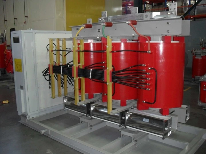
Like every other transformer of such size, three winding transformers can function in power stations, solar grids, and wind mechanisms. But, this type of transformer is essential because it distributes varying voltages and current through the secondary and tertiary winding.
In this case, such transformers can provide power for auxiliary equipment, appliances, and accessories. These include fans, lights, office spaces, and other equipment for the proper function and safety of the power station. Such power may differ from the secondary winding, but it can still ensure safety as the station generates power to the outside.
Typical transformers usually have a pair of windings attached to the core. The primary winding provides input voltage from the power source, while the secondary winding distributes the output voltage to the load. But, the number of 3 phase transformer windings may vary depending on the configuration. Here are some configurations that you need to know:
It refers to the direct connection from a set of windings. In this case, the number of windings may be two or three. There will always be one primary (input) winding, a secondary (output) winding, and a tertiary winding. The last one can serve as a line where output voltage flows to auxiliary equipment for power.
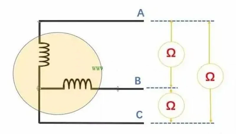
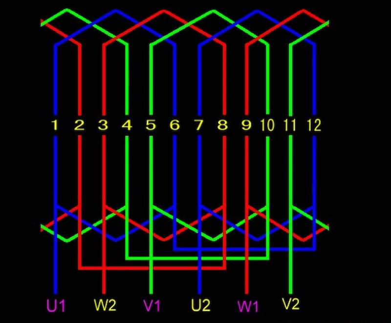
Once you utilize three sets of single-phase windings, you will have a transformer with a three-phase configuration. It entails having three primary and three secondary coils connected in a wye-wye setup. In this case, the delta tertiary winding shaped like a triangle will mediate between the two connections.
Multiple winding transformers involve the use of more than two windings in a transformer. It can happen with two primary windings combined to provide higher input power. It can also connect three secondary windings with various output capacities.
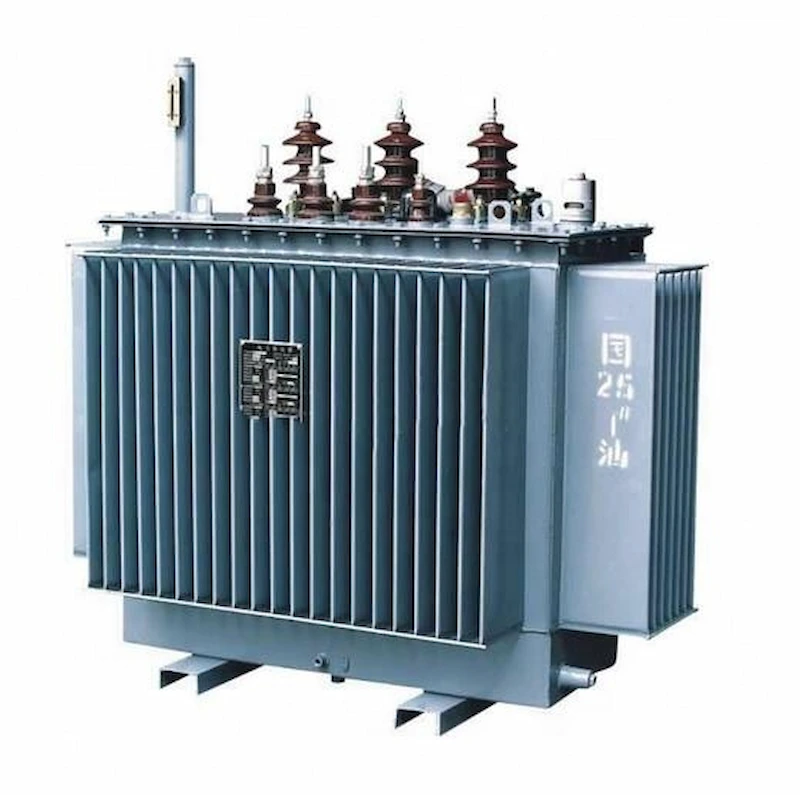
Believe it or not, there are a wide array of 3 phase transformer windings according to size and capacity relative to the voltage. Most of these are applicable in core transformers, but some are also useful in shell-type transformers. Here are the common types of windings present in electrical transformers:
These low-voltage rectangular or round shape windings operate on 6.6 kV for up to 600-750 kVa. It also has a 10 to 600A current rating. Under this category are multi-layered cylindrical windings that function on a higher voltage (33 kV, 800 kV) and current (80A).
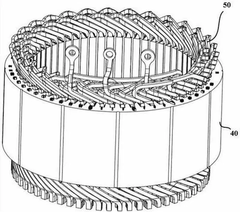
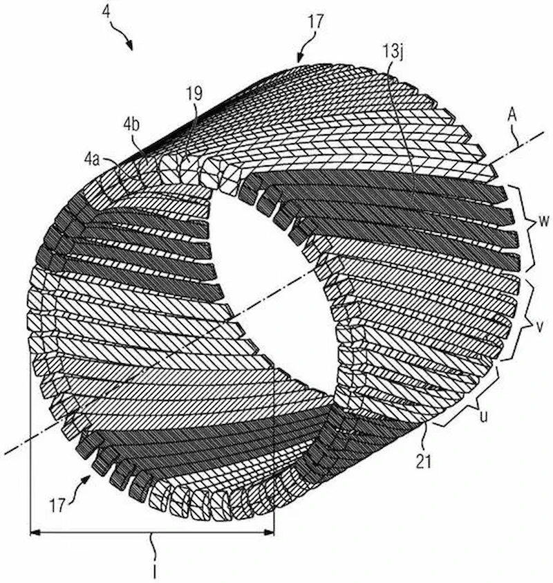
Single, double, disc-helical, or multi-layer windings function on a higher current. It has a transformer output ranging between 0.23 to 15 kV at 160 to 1000 kV. A maximum of 16 strips is used for the transformer’s conductor.
Among all the helical windings, the multi-layer windings operate more on high-powered transformers beyond 110 kV.
These paper-covered round strip windings are helpful when the transformer utilizes higher voltage. These windings are separated within 0.5 to 1 mm apart to lessen the voltage-operated within the transformer.
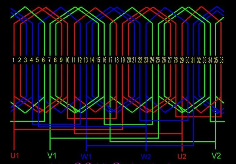
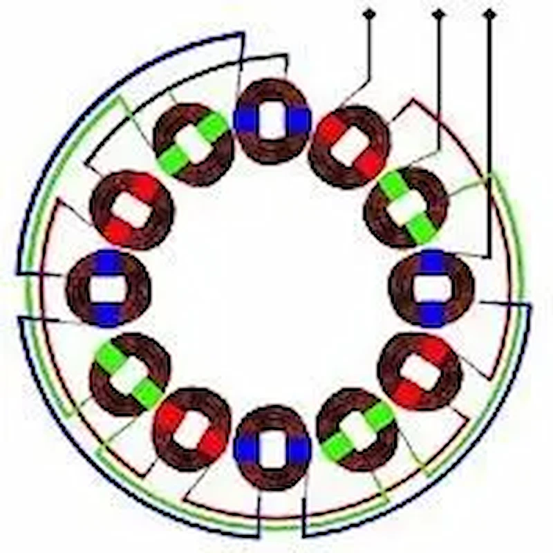
Windings of this kind have flat discs or coils that are placed parallel to each other. Rectangular strips are attached alternately — on the nearest discs on one series and the farthest discs on other series. There are also “pressboard sectors” located in between the discs. This type is capable of high-voltage operations and at a 12 to 600 A current range.
A common feature in shell-type transformers, sandwich winding, refers to the structure of windings through sections. These alternatively separate the windings of high voltage and those of low voltage.
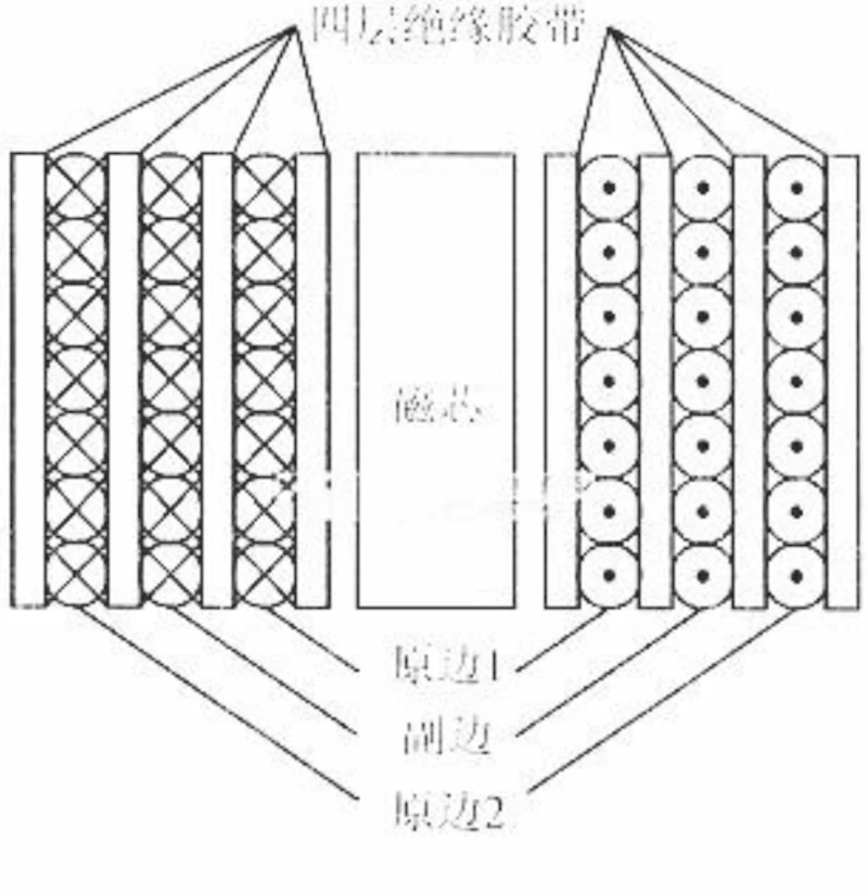
This kind of winding is recommended for its stable design and form, ability to lessen the leakage flux, mitigate short circuit faults.
No. Three-Phase Transformers consist of three sets of single-phase transformers for larger voltage transfers. Unlike three-winding transformers that utilize a group of primary, secondary, and tertiary windings, three-phase setups have six windings. These six windings comprise three primary and three secondary windings.
The connection for three-phase transformers is much more complex, utilizing delta, wye, and star configurations. But, a delta-type tertiary winding helps balance the voltages in a wye-wye setup.
The primary winding refers to the line and coil attached to the main power source. It is part of the primary side of the transformer setup as input voltage from the start flows from this side.
Sandwich winding refers to the shell-transformer setup where window-like sections separate coils. These windows are further divided into sections that separate high power and low power coil segments. This setup allows mutual inductance and lessens the leakage flux in a functioning transformer.
Transformer efficiency refers to the input-output power of the transformer relative to its performance and lifespan. When the amount of copper loss and iron loss is even, this usually signifies maximum efficiency. There are several formulas in determining a transformer’s efficiency.
A 3 winding transformer is a form of single-phase setup that requires primary, secondary, and tertiary winding. Unlike the more common transformers with only the primary and secondary winding, the former has a tertiary winding for low-voltage output.
This type of transformer setup is beneficial in providing low-output power for appliances and safety equipment in power plants. It also ensures a voltage balance and protection against harmonics and floating neutrals in a three-phase setup.
Daelim has you covered when talking about a safe, efficient, and highly reliable 3 winding transformer! For 15 years, Daelim has mastered the craft of producing safe and powerful electrical equipment for power grids and similar stations.
You also do not need to worry, as Daelim complies with international standards to assure the safety of the equipment. So, whether you’re looking for a three-winding transformer or other electrical equipment, Daelim guarantees quality.
If you’re interested in Daelim’s products and services, please drop a line for more details and inquiries.
When you need to find more than just existing transformers, Daelim’s Transformer Service Center can help you design and produce distribution transformers that meet your unique needs.
We have our own factory and a professional team of engineers, which can design and modify application requirements that meet all your conditions.
Download Resource
ELECTRIC, WITH AN ENGE-- DAELIM BELEFIC
After filling in the contact information, you can download the PDF.