ELECTRIC, WITH AN EDGE
Combining the calculation of bus voltage and motor voltage fluctuation and the calculation of transformer load rate and overload capacity, the 10kv transformer capacity is reasonably determined.
Generally, the medium-sized mine air compressor room has a large equipment capacity and low-voltage power distribution.
The layout of the air compressor room should be close to the wind load center. The main transformer substation of the mine is arranged in the power load center.
If it is far away from the wind load center, this kind of large-capacity low-voltage equipment must consider high-voltage power transmission.
A 10kV transformer is set up in the air compressor room. After stepping down, supply power to the air compressor.
Considering the rationality of the power supply plan and combining technical and economic factors, the 10kV transformer in the air compressor room can be used as a regional substation to supply power to the surrounding units of the air compressor room far away from the main substation of the mine. , Improve power supply reliability, save cable investment, and reduce cable voltage drop loss.
The substation and the air compressor room are connected together, and there is a high and low voltage power distribution room, and the main wiring form adopts a line transformer group.
There are two high-voltage power distribution cabinets in the institute, two SGB13 dry-type transformers, and several GCS-type low-voltage power distribution cabinets.
According to the load classification of the “Coal Industry Mine Design Specification”, the mine air compressor is a second-level load and should be powered by a double-circuit power supply. The high-voltage side adopts a line transformer group, and the low-voltage side adopts a single busbar section.
In addition to power distribution for air compressor equipment, low-voltage distribution also supplies power distribution to individual buildings around the air compressor room, such as mine machinery repair room, pit wood processing room, miner’s lamp room, mine water treatment, etc.
In addition to the load of the air compressor equipment, the capacity of the transformer in the substation should also be included in the power load of other monomers.
Analysis of Performance Data of High Voltage Distribution Transformer
The transformer of this institute is a distribution transformer in a region, and a load of air compressor equipment is generally large.
The capacity of the transformer should be determined through the calculation of transformer load rate, overload capacity calculation, and bus voltage and motor voltage fluctuation calculation, which can be explained by an example.
The low-voltage side of the 10kV transformer in the air compressor room adopts a single busbar section. Two distribution transformers work in parallel at the same time.
Both sections of the low-voltage busbar are equipped with an air compressor and other electrical loads.
The load capacity is basically the same, so refer to the calculation of one of the sections. Here, section I of the bus is selected as the calculation reference.
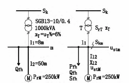
Figure 1 shows the I-section bus wiring diagram and equivalent circuit diagram of the 10kV transformer in the air compressor room.
The known conditions of the power distribution system are as follows: system short-circuit capacity Sk = 20 MVA, transformer capacity SrT = 1 MVA, XT = 0.06; dense bus 11 = 8m from the transformer to the low-voltage power distribution panel;
The line from the low-voltage power distribution panel to the air compressor is l2 = 50m, and the cables are 2 YJV-0.6/13×150+1×95 cross-linked polyvinyl chloride cables;
Technical parameters of air compressor M: PM = 250kW, IrM = 0.447kA; motor Y-△ starting current Ist = 1.67Irm = 0.746kA; other electrical loads on the low-voltage bus Pfh = 410kW, COSΦ = 0.85.
According to the electricity load calculation table of the load carried by the busbar of section I, when the capacity of the distribution transformer is 0.8 MVA, the load factor of the transformer is 0.84%, and the rated current of the low-voltage side of the transformer is 1.154 kVA.
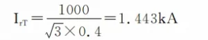
When the capacity of the distribution transformer is 1MVA, the load factor of the transformer is 0.67%, and the rated current of the low-voltage side of the transformer is 1.443kVA;
when the capacity of the transformer is 1.25MVA, the load factor of the transformer is 0.54%, and the rated current of the low-voltage side of the transformer is 0.54%.
The current is 1.804kVA. The load factor of the two transformers meets the requirements, but the load factor of the transformer with a capacity of 0.8 MVA is relatively high, and the load factor of the transformer with a capacity of 1.25 MVA is relatively low.
Taking into account the possibility of later reconstruction and expansion of the coal mine, transformers with higher load rates are not considered, so whether to choose a 1MVA or a 1.25MVA transformer, we need to verify the overload capacity of the transformer for air compressor startup.
In addition to the air compressor on the low-voltage side of the transformer, there are other electrical loads. Considering the peak current Ijf = KstIrM + IC’ (IC’ is the calculated current of the distribution circuit except for the starter motor, A) = 1.479kA. SGB13 dry-type transformer can continuously carry 1.05 times of full load, <20 minutes with 1.1 times of full load, <20 seconds with 1.25 times of full load;
The starting time of the air compressor is generally 15- 20S, so both 1MVA and 1.25MVA transformers can meet the overload requirements. In this case, it is economical and reasonable to choose a transformer with a capacity of 1MVA.
In the following, the bus voltage and motor voltage fluctuation calculations will be carried out for the transformer of this capacity to further verify the transformer. Reasonableness.
It is assumed that the impedance value of the dense bus from the transformer to the low-voltage distribution panel is negligible.
(1) Rated current on the low-voltage side of the transformer:
(2) Motor rated capacity:
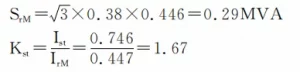
(3) Rated starting capacity of the motor:
(4) The impedance value of l2:
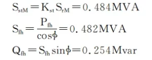
(5) Short-circuit capacity at the busbar on the low-voltage side of the transformer:
The input capacity of the circuit when the motor starts:
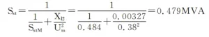
(6) The relative value of the busbar voltage of the substation when the motor starts is:
The voltage value on the bus of the substation when the motor starts is: 0.38×0.951 = 0.361kV
(7) The relative value of the terminal voltage when the motor starts is:
Then the terminal voltage value when the motor starts is: 0.38×0.941=0.357kV
According to “when the motor is started, its terminal voltage should be able to ensure the starting torque required by the machine, and the voltage fluctuation caused in the power distribution system does not hinder the operation of other electrical equipment”, and when the AC motor is started, the voltage on the power distribution bus The following requirements should be met:
The calculation result of this example shows that the bus voltage and the motor voltage are not lower than the voltage drop requirements when the motor starts, and the verification is passed.
The equipment load in the air compressor room is relatively large. If it is far away from the mine substation and adopts low-voltage power distribution, the line loss is very large and does not meet the relevant requirements of the wiring voltage drop. Therefore, the high-voltage (10kV) from the substation ) is The method of allocation.
The 10kV substation in the air compressor room can be used as a regional substation to provide power for the surrounding units of the air compressor room.
The selection of the capacity of the transformer in the 10kV transformer not only considers the influence of the starting current of high-power equipment on it, but also the influence of bus voltage and motor voltage fluctuations.
Combining multiple factors to select the transformer capacity, which ensures the reliability of power supply and avoids the waste of resources caused by unprincipled amplifying transformer capacity.
When you need to find more than just existing transformers, Daelim’s Transformer Service Center can help you design and produce distribution transformers that meet your unique needs.
We have our own factory and a professional team of engineers, which can design and modify application requirements that meet all your conditions.
Download Resource
ELECTRIC, WITH AN ENGE-- DAELIM BELEFIC
After filling in the contact information, you can download the PDF.