
How to Choose Pad Mounted Transformer?
Table of Contents Selecting the right pad-mounted transformer requires careful consideration of several critical
ELECTRIC, WITH AN EDGE
About the difference between three-phase power and two-phase power, the difference between three-phase power and single-phase power, the delta connection and Y-connection of three-phase power loads, the three-phase four-wire system and three-phase five-wire of three-phase power meters System, let’s get to know it together.
In the realm of power supply, the conversion from single-phase to three-phase power is a topic of great interest and practical importance. This article, based on the analysis of a comprehensive PDF document, aims to provide a detailed understanding of various conversion schemes, their advantages, disadvantages, and potential applications. The core focus will be on Three Phase Power, a critical aspect of modern power systems.
Three-phase power:
It is composed of three phase wires.
Mutual voltage: 380V.
Application: Three-phase motor
Two-phase electricity:
It consists of two-phase wires.
Mutual voltage: 380V.
Application: AC welding machine
Single-phase electricity:
It is composed of a phase wire and a neutral wire.
Voltage: 220V
Application: Household appliances.
Three-phase Power: when the coil rotates in a magnetic field, the wire cuts the magnetic field line to generate an induced electromotive force, and its changing law can be represented by a sinusoidal curve. If we take three coils and place them at an angle of 120 degrees apart in space, the three coils still rotate at the same speed in the magnetic field, and three induced electromotive forces with the same frequency will be induced. Since the three coils are 120 degrees apart in space, the current generated is also a three-phase sinusoidal change, which is called a three-phase sinusoidal alternating current. Industrial electricity uses three-phase electricity, such as three-phase AC motors.
The voltage between any two phases is 380VAC, and any phase-to-ground voltage is 220VAC. Divided into A phase, B phase, and C phase. The lines are represented by L1, L2, and L3.
The power generated by the generator is three-phase, and each phase and its neutral point of the three-phase power supply can form a single-phase loop to provide users with electric energy.
According to regulations, the neutral point of a 380 volt (three-phase) civil power supply should not be grounded at the entrance end. A ground wire is also connected to the three-core power jack.
(Grounding at the transformer end. This grounding is to take into account that the floating point cannot cause a point higher than the power supply voltage. The grounding of the user end and the grounding of the transformer end have a certain resistance in the earth)
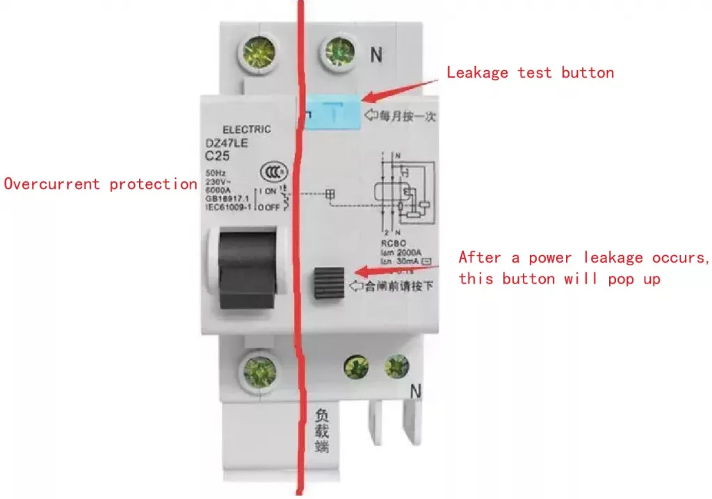
This is to take into account the realization of the function of the leakage protector. If the neutral point of the power supply is directly grounded, the leakage protector will lose its function and cannot protect the short circuit of the human body and electrical equipment.
The working principle of the leakage protector is: if the human body touches the line end of the power supply, namely the live wire, or the internal leakage of electrical equipment, the current flows from the live wire to the earth through the human body or the housing of the electrical equipment, and does not flow through the neutral wire, live wire and The current of the neutral line will be unequal, and the leakage protector will immediately trip to protect the safety of personal and electrical appliances after detecting this part of the current difference. Generally, the differential current is selected to be tens of milliamperes。
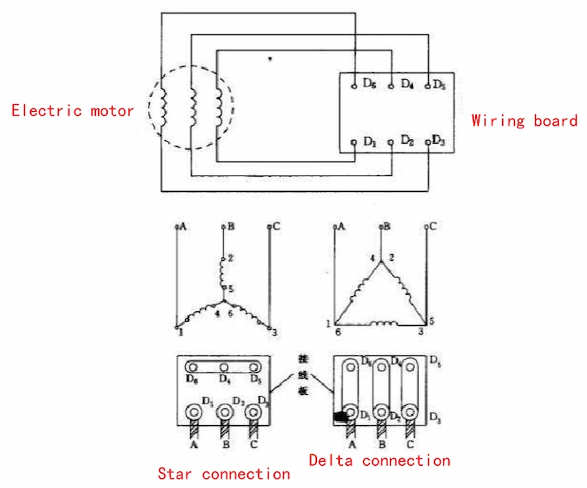
Divided into delta connection and Y-shaped connection.
The load leads of the delta connection are three live wires and one ground wire. The voltage between the three live wires is 380V, and the voltage of any live wire to the ground wire is 220V;
The load leads of the Y-connection method are three live wires, a neutral wire and a ground wire. The voltage between the three live wires is 380V, and the voltage of any live wire to the neutral wire or the ground wire is 220V.
The total power of a three-phase electrical appliance is equal to the voltage of each phase multiplied by the current of each phase and then multiplied by 3, that is, the total power = current × voltage (220V) × 3 (W = U × I × 3)
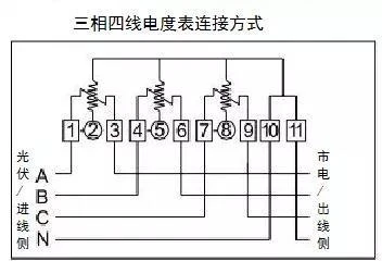
In the low-voltage distribution network, the transmission line generally adopts a three-phase four-wire system, of which three lines represent the three phases of A, B, and C, without splitting, and the other is the neutral line N。
In the 380V low-voltage power distribution network, the N line is set up in order to obtain the 220V line-to-line voltage from the 380V phase-to-phase voltage. In some cases, it can also be used for zero-sequence current detection to monitor the three-phase power supply balance
Repeated grounding: Regardless of N wire or PE wire, repeated grounding must be used on the user side to improve reliability. However, repeated grounding is only repeated grounding. It can only be connected together at the grounding point or close to the grounding point, but it does not mean that it can be connected together at any position, especially indoors. This must be remembered, and pay attention to whether your friend has violated it!
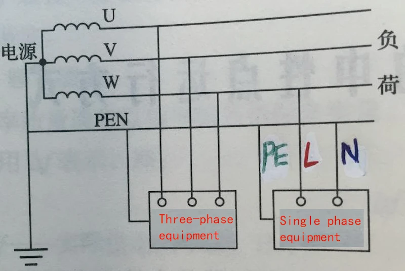
It is best to use standard and standardized wire colors in the application: A wire uses yellow, B wire uses blue, C wire uses red, N wire uses brown/blue, and PE wire uses yellow-green.
The three-phase five-wire system refers to the A, B, C, N and PE wires. Among them, the PE wire is a protective ground wire, also called a safety wire, which is specially used to ensure the safety of electricity use, such as the equipment casing. The PE line is connected to the N line at the power supply transformer side, but it must not be used as a neutral line after entering the user side, otherwise, it will be no different from a three-phase four-wire system after confusion.
However, since this kind of chaos makes people lose their vigilance, it may be more prone to electric shock accidents in practice. Now the power supply for residential houses has been stipulated to use a three-phase five-wire system. If yours is not, you can request rectification.
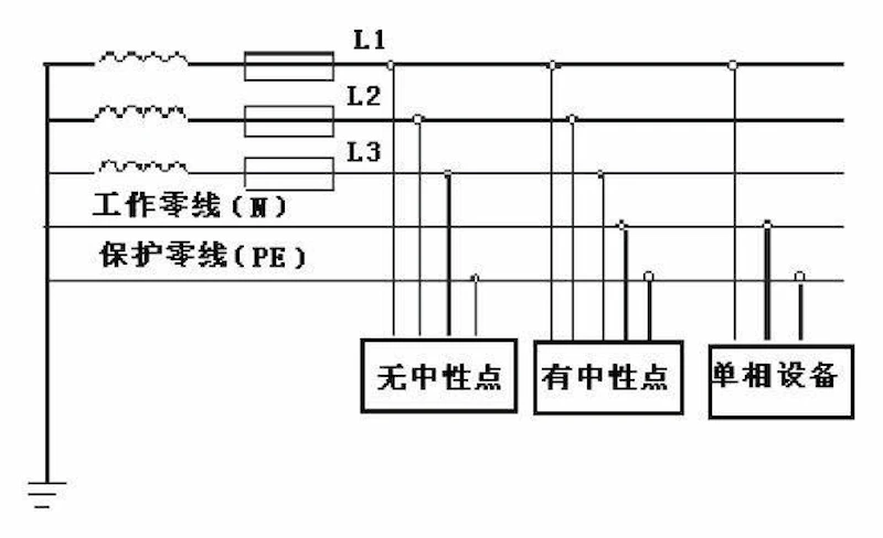
The three-phase five-wire system includes three phase wires (A, B, and C wires), a neutral wire (N wire); and a ground wire (PE wire).
The neutral line (N line) is the neutral line. When the three-phase load is symmetrical, the vector sum of the current flowing into the neutral line of the three-phase line is zero, but for a single-phase, the current is not zero. When the three-phase load is asymmetrical, the current vector sum of the neutral line is not zero, and a voltage to the ground will be generated.
The three-phase five-wire system is divided into TT grounding mode and TN grounding mode, and TN is specifically divided into TN-S, TN-C, and TN-C-S three modes.
The first letter T means the neutral point of the power supply is grounded, and the second T is the grounding of the metal casing of the equipment. This method is commonly used in high-voltage systems, but it is not suitable for low-voltage systems with large-capacity electrical appliances.
1. TN-S grounding method: The letter S means that N is separated from PE, the metal shell of the equipment is connected to PE, and the neutral point of the equipment is connected to N. The advantage is that there is no current in PE, so the potential of the metal casing of the equipment to the ground is zero. Mainly used for data processing, precision detection, and power supply system for high-rise buildings.
2. TN-C grounding method: The letter C means that N and PE merge into PEN, which is actually a four-wire power supply method. Both the neutral point of the device and the metal shell are connected to N. Since the three-phase unbalanced current and harmonic current flow when N is normal, the metal casing of the equipment normally has a certain voltage to the ground, which is usually used in general power supply places.
3. TN-C-S grounding method: part of N is separated from PE, which is a four-wire half system power supply method, which is used in places with poor environment. When N and PE are separated, they are not allowed to be combined.
Electricity is similar to water, so let me explain the phenomenon of water:
The current is similar to the water flow, and the voltage is also called the potential difference. It is similar to the water level difference. Two water bottles are used to connect them with a thin tube.
If two bottles are placed on the same level, there will be no water flow in the thin tube, but if one bottle is raised, water flow will be generated, that is, the water flow will flow from the high bottle to the low bottle.
For example, 3 bottles of ABC are used, and then 3 thin tubes are used to connect the 3 bottles respectively (that is, to form an angular connection). flow, B also flows to C.
If C is raised by 20CM, it is found that A flows to BC, but C flows to B. The reason is that water flows from high to low.
The current of the alternating current changes in positive and negative directions, just as the bottle moves up and down on a level, making the direction of the water flow in the water pipe change positive and negative.
Three-phase electricity, such as ABC 3 bottles are moving up and down periodically, but they do not move up and down at the same time, but staggered by 1/3 of the change cycle, so that there will be differences between ABC and 3 from time to time. The potential difference that causes the connected load to generate current.
This is the reason why three-phase electricity can energize the load without using 0 wire.
Three-phase alternating current is a form of transmission of electrical energy, referred to as three-phase electricity. A three-phase AC power supply is a power supply composed of three AC potentials with the same frequency, the same amplitude, and a phase difference of 120° from each other.
Three-phase alternating current has many uses, and most of the alternating current electrical equipment in the industry. For example, electric motors use three-phase alternating current, which is often referred to as three-phase four-wire system. In daily life, single-phase power is often used, also known as lighting power.
When using lighting electricity for power supply, use one of the three-phase electricity to supply power to the electrical equipment. For example, household appliances, and the other wire is the fourth wire among the three-phase and four-wire, that is, the neutral wire, which is drawn from the neutral point of the three-phase electricity.
Two-phase power refers to 220-volt single-phase power;
Two-phase power means that the rated voltage of the electrical appliance is 380 volts, and it needs to be connected to two phase wires, that is, two live wires.
Single-phase power is a form of power transmission consisting of a single live wire and a neutral wire, and there will be a third wire (ground wire) when necessary.
Generators that can generate potentials with equal amplitude, equal frequency and 120° phase difference are called three-phase generators;
A three-phase power generator is used as a power source, which is called a three-phase power supply;
A circuit powered by a three-phase power source is called a three-phase circuit. U, V, W are called three-phase, and the voltage between the phases is the line voltage, and the voltage is 380V.
The phase voltage between the phase and the center line is called the phase voltage, and the voltage is 220V.
The difference between three-phase power supply and single-phase power supply: the power supply from the generator is three-phase, and each phase of the three-phase power supply and its neutral point can form a single-phase loop to provide users with power energy.
Note that the AC circuit can not be called positive or negative, it should be called the line terminal (called the live wire in the civil electricity) and the neutral wire (called the neutral wire in the civil electricity).
The alternating current on the same grid has the same voltage phase. Therefore, the neutral lines of multiple transformers on the same power grid (National Grid) can be used with each other. And the voltage between the live wire and the neutral wire of any transformer is 220v.
However, when used in this way, the live wire and the neutral wire are often separate, and there is a great concern for communication lines such as TV sets and radios, which are generally not allowed by the country and the power supply.
In general, the neutral line (the neutral point of the secondary side) is repeatedly grounded with the ground line, which plays a double protective role, and its main function is to be used in the working circuit of the equipment.
You need to know that the neutral line entering the ground is sent to the user in parallel with the three-phase line as the main line. Under normal circumstances, there should be no electricity on this neutral line. Once it is short-circuited, it will be charged.
Therefore, if two transformers share a line, it means that there is current from the loop, which will cause electromagnetic induction.
Just because one of the transformers does not have a good grounding below 4 ohms, there is no good loop. Once there is leakage between the equipment and the shell, it is dangerous if there is no tripping.
The neutral lines of different systems must not be borrowed and used each other. If the neutral point of the No. 1 transformer is not well grounded, and the zero potential drift and zero position rises, then the neutral point of the No. 2 transformer is connected to the neutral point of the No. 2 transformer. It happens that the grounding resistance of the neutral line of the No. 2 transformer is too large. , it will make the zero position of the transformer rise, so that the three-phase four-wire load is no longer balanced. Because the No. 1 change-to-zero line is borrowed, a fault in the line will not cause the circuit breaker to trip and expand the fault range, endangering equipment and personal safety.
In the past, when there were multiple transformers, when supplying power, the neutral lines of each transformer were all connected.
Not now, the control of the outgoing line of the distribution transformer is all leakage protection. If the live wire of this distribution transformer and the neutral wire of the other distribution transformer are used, the leakage protection cannot be closed.
If there is no leakage protection, then use the zero line distribution change. The ground line voltage is very high, which is prone to accidents and electric shock accidents.
Transformers have three-phase circuits, and there are various interfaces for such three-phase circuits, and there are many ways to connect various lines.
In the process of common connection, the connection should be correctly carried out to realize the continuous improvement of the performance of the transformer.
However, these three-phase circuits of the transformer should be continuously connected correctly to improve the accuracy. But some people will ask, what will happen if the three-phase power of the transformer is reversed?
For example, for the three terminals of transformer ABC, if I connect the lines in the way of A-C B-B C-A, then the coiler at the output end will also be the law of A-C B-B C-A.
That is, if the ABC three-phase connection is reversed on the input side, the output side is also reversed.
But if the connection is reversed, it is all reversed. Generally, there will be no problem with small transformers (household power supply), and micro-transformers (several kilowatts) will be fine no matter how they are connected in reverse.
But the efficiency has dropped, but the large transformer is absolutely not allowed to reverse.
In the case of high load, the reverse connection usually produces some serious consequences of the unpredictability of the bending machine. This is not only a drop in efficiency, but also because the sequence of the phase changes the bending machine, and there are some conflicts with the magnetic structure designed by the transformer itself. , and the transformer needs to consume the energy generated by the conflict and generate severe heat, which is dangerous at this time.
Therefore, the three-phase power of the transformer must not be reversed. If it is reversed, it will be dangerous. At that time, your transformer will be in danger, and casualties will easily occur. Therefore, the transformer must be operated scientifically and connected correctly!
There are five main techniques of transforming single-phase power to three-phase power:
Single-phase motor-driven three-phase generator power supply plan
“Dual-stage Electricity Distribution System”
Power supply configuration consisting of a frequency transformer for voltage boost, unchecked rectification, and a three-phase bridge inverter.
A power supply plan combining two-fold correction and a three-phase bridge inverter.
Power supply design that makes use of unrestrained rectification, ch, and a three-phase inverter circuit.
Each of these techniques has its own distinct advantages and negative aspects, making them ideal for different applications.
A power supply system making use of a three-phase generator driven by a single-phase motor.
This is the earliest technique of single-phase to three-phase power supply. It includes utilizing a single-phase power supply to drive a single-phase motor-driven three-phase generator to result three-phase voltage for providing three-phase loads. While this technique is straightforward and standard, it struggles with reduced conversion performance, high expense, and heavy weight, making it troublesome for transport in remote backwoods.
The split-phase approach can obtain a little ability three-phase power supply, which can be utilized to supply tiny power three-phase lots. The outcome voltage is three-phase by utilizing a capacitive inductor to move the phase at the input. However, this method has a small capacity, poor tons lugging capability, and inadequate vibrant efficiency.
Power supply style making use of frequency transformation for voltage rise along with uncontrolled correction and a three-phase bridge inverter.
This technique uses a step-up transformer, a single-phase rectifier circuit without control, a filter inductor, a DC energy storage space capacitor, a three-phase bridge inverter circuit, and an LC filter circuit. It streamlines the wiring and lessens the need for regularity transformers, thereby minimizing the overall complexity of the system. In addition, it reduces the reliance on energy storage capacitors and lightens the devices’s weight.
A power supply scheme that incorporates the benefits of two-fold rectification and a three-phase bridge inverter for optimal effectiveness and dependability.
This system makes use of a twin rectifier circuit on one end, a voltage-reducing step-down chopper circuit in the facility, and a three-phase bridge inverter circuit on the other end. By getting rid of the demand for frequency transformers on the input side, it efficiently decreases the weight and dimension of the power conversion gadget. This simplifies transport and setting up, making it viable to release the gadget in remote locations doing not have three-phase power accessibility.
The two-fold rectification plus three-phase bridge inverter power supply system has both benefits and drawbacks. On the one hand, it supplies high power quality and high effectiveness, making it an ideal choice for applications that require a dependable power supply. Furthermore, it has a straightforward and compact structure, that makes it very easy to install and keep. However, on the other hand, it has a greater price compared to various other power supply schemes, and it can be conscious load variants, which can impact its performance.
The dual-purpose rectification and three-phase bridge inverter power supply system is a reliable method to convert single-phase power to three-phase power, specifically for high voltage, reduced present applications. While it has a solid track record of effectiveness, it does have limitations, consisting of a lowered lots ability and a reduction in result voltage when power demands are reduced.
Advantages of the two-fold rectification plus three-phase bridge inverter power supply plan
This scheme is helpful as it avoids making use of frequency transformers on the input side, which effectively minimizes the weight of the power conversion gadget, minimizes the size of the gadget, and makes it simpler to carry and assemble this gadget to remote areas where it is challenging to request three-phase power. It remains in line with the development of household home appliances to give a smaller impact of three-phase power supply.
Downsides of the two-fold correction plus three-phase bridge inverter power supply plan
The two-fold correction plus three-phase bridge inverter power supply plan has a reasonably inadequate lots capability. The outcome is really tiny power, it will bring about a significant decrease in outcome voltage, in the output side can not access the power of a larger lots. Making use of capacitors in series likewise causes a reasonably huge DC side outcome voltage ripple.
The two-fold rectification and three-phase bridge inverter power supply scheme is well-suited for applications that need high voltage and low present. It can deliver up to 2.8 times the AC input voltage in DC voltage, removing the demand for a high-ratio step-up transformer. Additionally, the rectifier elements can be developed with reduced holding up against voltage values, making the general system a lot more efficient and cost-effective.
Future potential customers of the two-fold rectification plus three-phase bridge inverter power supply scheme
With the continuous development and renovation of power electronic devices modern technology, the two-fold correction plus three-phase bridge inverter power supply plan is anticipated to have broader application leads. It can be further maximized and boosted to meet the diverse demands of various applications.
The cutting-edge power supply system that combines unrestrained correction, chopper regulation, and a three-phase bridge inverter circuit is a contemporary and reliable means to convert single-phase power into three-phase power. Its structured design, exceptional vibrant efficiency, and high power top quality make it a suitable option for various applications.
The system includes a straightforward circuit style, excellent vibrant capabilities, and premium power dependability. By eliminating the requirement for frequency transformers and minimizing the circuit intricacy, it also reduces the dependence on energy storage space capacitors and reduces devices weight. This results in a portable, lightweight system with strong vibrant efficiency and high power top quality, conference customers’ needs for superior power supply.
The proposed system provides numerous benefits, however it additionally provides some difficulties. One of the primary limitations is the requirement for precise law of the chopper circuit to maintain a secure outcome voltage.
The versatility and effectiveness of this plan make it a prominent choice across various industries. Its ability to provide high power quality and keep a steady result voltage makes it perfect for applications that call for specific efficiency, such as medical gadgets, interaction systems, and accuracy equipment.
The improvement of power electronic devices innovation is anticipated to expand making use of the uncontrolled rectification plus chopper law and three-phase bridge inverter circuit power supply scheme. This scheme can be more polished and customized to accommodate numerous application needs.
Transforming single-phase power to three-phase power making use of a single-phase motor to drive a three-phase generator is an usual technique known as the single-phase motor-driven three-phase generator power supply system. This technique uses the single-phase power supply to run the electric motor, which in turn powers the generator to produce three-phase voltage for running three-phase devices.
In this plan, a single-phase source of power is utilized to operate a single-phase motor. The electric motor is then connected to a three-phase generator, which generates three-phase voltage for powering three-phase equipment. While this method is uncomplicated, it encounters obstacles in regards to effectiveness and cost.
While this technique is easy and standard, it experiences low conversion efficiency, high cost, and hefty weight, making it bothersome for transport in remote rural areas. Nevertheless, it is still commonly utilized in areas where the demand for three-phase power is low.
Use the system where a single-phase electric motor drives a three-phase generator to supply power.
This technique is frequently utilized in small-scale sectors and rural areas where the need for three-phase power is not considerable. It is additionally utilized in emergency power supply systems to provide short-lived three-phase power throughout power interruptions.
Developments in power electronic devices modern technology have resulted in the development of more structured and effective methods for transforming single-phase power right into three-phase power. Nonetheless, the strategy of using a single-phase motor to drive a three-phase generator power supply still confirms important in specific circumstances due to its straightforwardness and reliability.
The regularity transformer boost plus unchecked correction and three-phase bridge inverter power supply system is a contemporary method of transforming single-phase power to three-phase power. It is defined by its high performance, compact size, and excellent vibrant performance.
The operating system of the approach includes enhancing the voltage making use of a regularity transformer, followed by an unchecked correction process, and finally, a three-phase bridge inverter power supply plan. The regularity transformer step-up part boosts the input voltage, allowing the system to run at higher degrees. Afterward, the unchecked correction process converts the air conditioning result from the transformer into DC voltage. Lastly, the three-phase bridge inverter power supply scheme makes certain the efficient conversion of DC voltage to AC voltage, leading to a stable outcome voltage.
The system includes an IFT step-up transformer, a single-phase uncontrolled rectifier, a filter inductor, a DC power storage space capacitor, a three-phase bridge inverter, and an LC filter. The transformer improves the voltage, the rectifier changes a/c to DC, and the inverter changes DC back to three-phase a/c.
The major advantage of this scheme is its high efficiency and small size. It avoids the use of frequency transformers and decreases the intricacy of the circuit, while lowering using energy storage capacitors and lowering the weight of the equipment. Nonetheless, it needs specific control and defense circuits to make certain stable and secure operation.
The usage of a regularity transformer step-up, along with uncontrolled rectification and a three-phase bridge inverter power supply plan, has various sensible applications.
This system is commonly utilized in various fields as a result of its high effectiveness and portable dimension. It is particularly ideal for applications that need high power high quality and steady result voltage, such as accuracy machinery, clinical devices, and interaction devices.
The possible end results of using a frequency transformer with unchecked correction and a three-phase bridge inverter power supply setup.
With the continuous development of power electronic devices modern technology, this scheme is anticipated to have more comprehensive application prospects. It can be further enhanced and boosted to meet the diverse needs of various applications.
In conclusion, the conversion from single-phase to three-phase power is a critical aspect of modern power systems. Various methods, each with its own unique advantages and disadvantages, are available for this purpose. The choice of method depends on the specific requirements of the application, including factors such as efficiency, cost, size, and power quality. As power electronics technology continues to advance, we can expect to see further improvements in these methods, making them even more efficient, compact, and versatile.
For more information, check out these similar blogs:
A Complete Guide to 3 Phase Transformer
The three-phase 3 Phase Transformer is widely used to generate, transmit and distribute electrical power to industrial and commercial businesses.
A Complete Guide to Single Phase Distribution Transformer
Consumers use electricity for different industries. Transformers work to make this happen as single phase distribution transformers.
How to Wire a Push Button Switch?
Do you know how to wire a push button switch? There are many ways of wiring the same button, let me introduce you to several common wiring methods.
Table of Contents Selecting the right pad-mounted transformer requires careful consideration of several critical

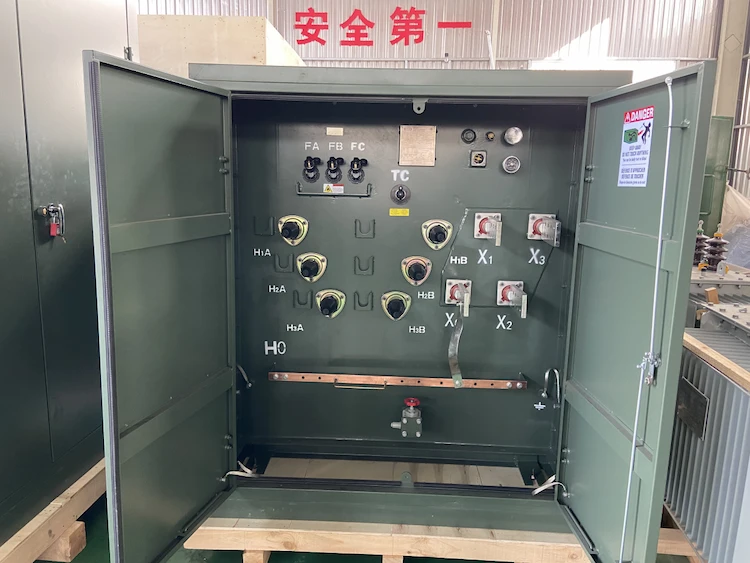
The primary function of the pad mounted transformer is to serve as a critical distribution

A pad mounted transformer operates through electromagnetic induction, serving as a crucial distribution component that
ELECTRIC, WITH AN ENGE-- DAELIM BELEFIC
After filling in the contact information, you can download the PDF.