
How to Choose Pad Mounted Transformer?
Table of Contents Selecting the right pad-mounted transformer requires careful consideration of several critical
ELECTRIC, WITH AN EDGE
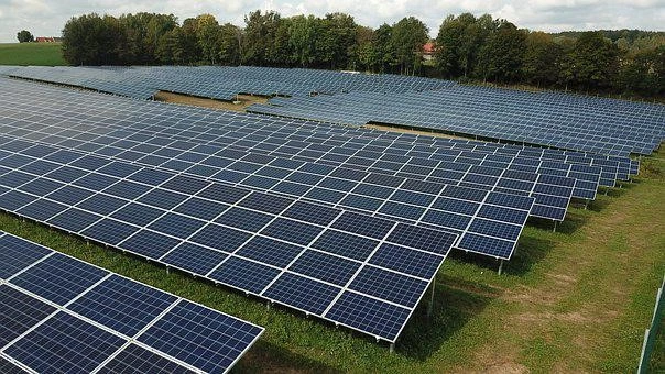
Most new energy stations, whether wind farms or Solar power plants, use the local step-up method to raise the voltage to 10/35 kV, and then collect the power lines to the busbar of the step-up station and connect to the grid after the secondary step-up. Solar power stations cause certain economic losses, so it is necessary to find out the reasons for the destruction of the Solar transformer at the end of the Step-up transformers collector line to provide a basis for solving such problems.
The information collected on several occasions when Solar transformers in Photovoltaic power plants failed, in the hope that some breakthrough points could be found from this information to support the search for the cause of Solar transformer damage, is as follows.
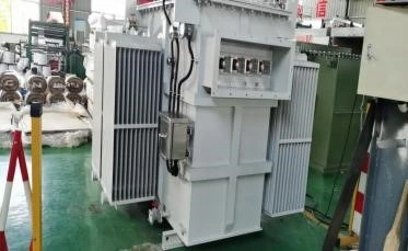
System overview: A Solar power plants system overview: installed capacity 20 MW, connected to the grid voltage level of 35 kV, Step-up transformers capacity 1 MVA, double split dry Solar transformer, Step-up transformers high voltage side rated current 15 A, connection Group Dy11y11, each collector line with 5-7 step-up solar power transformers, 35 kV system grounding method for arc extinguishing coil grounding method.
Fault 1: 05:34 am, clear, no load, set line BC phase current suddenly increased to about 27 A, phase difference of 180 °, duration of about 200 ms after the trip, the cause of the fault is the end of the set line Step-up transformers B phase winding inter-turn short circuit.
Fault 2: 20:20 pm, clear, no load, sudden increase in AC phase current to 25 A, phase difference 180°, tripping after a duration of approx. 100 ms, fault due to short circuit between turns in phase C winding of Step-up transformers at the end of the collector.
Fault 3: 20:27 pm, clear, no load, sudden increase of current in phase AB of the collector wire to about 32 A, phase difference 180°, duration about 2 s after tripping, the cause of the fault is a short circuit between the turns of phase A winding of the Step-up transformers at the end of the collector wire and a fault in the insulation breakdown of phase B winding to ground.
Through the analysis of several fault phenomena and the comparison of the reports after the Solar transformer was dismantled at the factory, it was determined that the cause of several fault trips was a short circuit between the turns of the Solar transformer, so the following investigation was done to identify the possible causes of the short circuit between the turns of the Solar transformer.
Solar transformer operation under overvoltage will lead to saturation of the Solar transformer core, causing local overheating of the Solar transformer. The high temperature will shorten the service life of the insulation material, making it brittle and cracked, accelerating insulation ageing and eventually leading to insulation breakdown accidents.
By comparing several incidents, the damaged Solar transformers were all at the end of the collector lines, mostly at night when there was no load, while Solar power stations mostly use cable lines with high capacitive currents.
By looking at the monitoring background history curve, the highest voltage of the 35 kV bus of the PV station are around 38.8 kV at around 12 noon, when the load current is close to full load, Solar transformer block running at 37 kV position, while at night when the line is empty, the 35 kV bus voltage is around 37 kV, the inverter voltage at the end of the collector line is over 7% or so This translates into a voltage of around 39.3 kV on the high voltage side, which does not exceed the maximum device voltage of 40.5 kV.
The temperature on the surface of the pad mounted transformer rises from the bottom up, with no obvious temperature difference found. 117 °C is the maximum temperature at noon and 99 °C at night. 10-15 °C is the temperature difference between the upper and lower part of the pad mounted transformer.
The grounding system is a grounding system for the arc extinguishing coil, arc extinguishing coil operation in the under-compensated state, there may be resonant overvoltage, so the arc extinguishing coil was checked, the inspection found that the arc extinguishing coil has been running in the highest gear 15 and in the under-compensated state, in order to find out the current 35 kV system capacitance current specific how large, the 35 kV system capacitance current was measured, the results show that the actual system In order to find out the current capacitance current of the 35 kV system, the actual measurement of the capacitance current of the 35 kV system was carried out, the result showed that the actual system current was 16.4 A, which did not reach the rated current value of 27 A of the arc extinguishing coil.
After checking the fault recording voltage waveform, no significant voltage rise was seen during normal operation, nor was the phenomenon of PT saturation leading to voltage waveform distortion, so it was considered unlikely that resonant overvoltage would cause damage to the Solar transformer.
Harmonics will not only cause voltage transformers, Solar transformer core saturation resulting in harmonic overvoltage generation, but also cause Solar transformer local overheating, accelerate the insulation of electrical equipment aging, reduce service life, Photovoltaic power plants harmonic sources mainly from the inverter, photovoltaic unit Step- This wiring method provides a pathway for the third harmonic on the low voltage side to circulate on the high voltage side.
Therefore, the power quality of the inverter output current and voltage is monitored and it is found that the current 5th harmonic content is higher when the load is below 30%.
The harmonic content of the voltage on the low voltage side of the pad mounted transformer was found to be in line with the requirements. A check of the fault recordings revealed that the 5th harmonic content of the collector current was high at low loads in line with the low voltage side of the pad mounted transformer.
The 35 kV bus voltage was then tested for power quality and no abnormalities were found. Further testing revealed that the fault recording voltage circuit was incorrectly wired and the N line was mistakenly connected to the fault recording zero sequence circuit resulting in a high 3rd harmonic content.
It is therefore considered unlikely that the high harmonic content caused local overheating of the Solar transformer resulting in damage to the Step-up transformers.
The Solar power plants were flooded in the summer of 2016 and the flooding reached the bottom of the windings of the pad mounted Step-up transformers, resulting in a power outage of up to six months.
All Step-up transformers in the station were then tested, and those that passed the test were put back into operation, while those that failed were replaced. Several other Solar transformers here have been replaced after failing the tests carried out after the flooding, so it is more likely that this Solar transformer was damaged as a result of the flooding.
As the load changes day and night, more moisture will invade the Solar transformer room at night, which will cause the insulation material of the dry Solar transformer to age and crack and eventually lead to the breakdown of the inter-turn insulation, leading to accidents.
Due to the double split dry Solar transformer high voltage side of the two groups of split coils placed up and down, due to the influence of air convection up and down, the lower winding coil temperature is significantly lower than the upper about 15 k, manufacturers in the manufacture of insulation materials if not to strengthen the level of heat resistance, uneven heat for a long time, easy to lead to insulation coil insulation damage caused by inter-turn short circuit fault.
In addition, the Solar transformer is wired with Dy11, which increases the voltage of the high-voltage side angle connection by a factor of √3 compared to the star connection, increasing the inter-turn voltage gradient inside the Solar transformer winding, which makes the Solar transformer with Dy11 more susceptible to partial discharge than the Solar transformer with Yd11. The possibility of partial discharge is greater.
Through the above inspection, it is believed that Solar power stations no-load operation of the collector line at night, due to the effect of capacitance rise, will make the end of the collector line there is the phenomenon of voltage rise, the end of the collector line overvoltage will lead to the end Solar transformer local overheating, plus Solar transformer due to air convection reasons winding There is a temperature difference of around 15°C between the windings of the Solar transformer and the winding.
If the manufacturer does not strengthen the thermal class of the Solar transformer insulation material in response to the characteristics of day and night load changes in Photovoltaic power plants, the Solar transformer overheating will enlarge the weak point of the Solar transformer inter-turn insulation, leading to insulation breakdown and causing accidents.
Many Solar power plants have the phenomenon of Solar transformer faults at the end of collector lines, and the causes of faults can vary. In order to enable early detection, early prevention, early preparation and planned elimination of equipment defects, the following recommendations are made.
(1) Install partial discharge online detection devices to detect the presence of partial discharge in Solar transformer in real time.
(2) Strengthen the daily maintenance work of the arc extinguishing coil to avoid under-compensation operation of the coil.
(3) When selecting equipment, it is recommended that PV Step-up transformers should be wired in Yd11 connection mode to improve the voltage gradient between turns of the coil.
It is recommended that manufacturers strengthen the insulation material heat resistance level of Solar power stations Step-up transformers.
Download Resource
Table of Contents Selecting the right pad-mounted transformer requires careful consideration of several critical

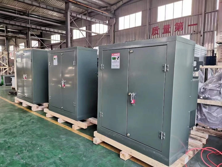
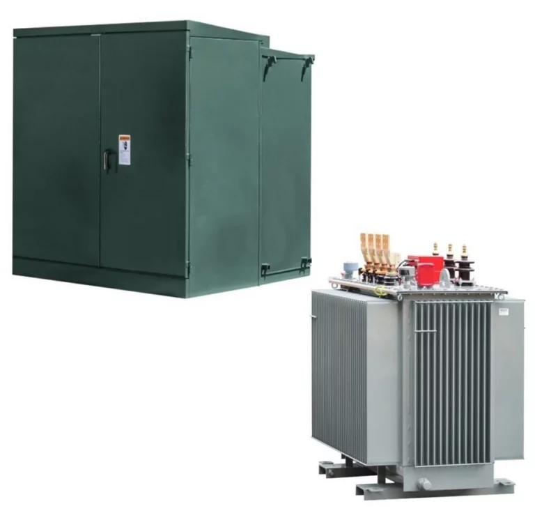
The primary function of the pad mounted transformer is to serve as a critical distribution

A pad mounted transformer operates through electromagnetic induction, serving as a crucial distribution component that
After filling in the contact information, you can download the PDF.