ELECTRIC, WITH AN EDGE
When it comes to transformers, it is fairly common to hear power transformers, which is why this article will be focused on the power transformer diagram and as well as the different types of transformers including step-up transformers.
Moreover, it is important to discuss the parts of a transformer as well.
In this article, DAELIM, one of the best power transformer manufacturers in the world, will provide you with all the necessary information needed for you to understand what power transformer diagrams are all about.
But first, it is also crucial that you learn the fundamentals of a transformer first before we go through the power transformer diagrams so that you will not be confused as we go deeper into the article.
IEC 60076 -24:2020: Specification of voltage regulating power transformers
-IEC 60076-24:Specification of voltage regulating power distribution transformers (VRDT) . Daelim has produced the power transformer since 1996.
15+FAQ ABOUT THE 3 PHASE PAD-MOUNTED TRANSFORMER
-3 PHASE PAD-MOUNTED TRANSFORMER is a highly integrated transformer. It is widely used in power systems. Learn more about 3 PHASE PAD MOUNTED TRANSFORMER (including how to buy them) in this new guide.
2021 A Complete Guide to Power Plant Transformer
-Learn the fundamentals of the Power Plant Transformer, including what is it, how does it work, Typical Ratings, Applications, and custom options.
14+FAQ ABOUT THE POWER TRANSFORMER IN SUBSTATION
-Power transformers in substations play a vital role in distributing electricity to their consumers, especially other transformer substation types. This article will provide you full details about this topic.
Step-Up Substation and Its Significance In Power Distribution
-Daelim provides in-depth analysis of the step-up substation. Read on and understand what is it about and its significance in power distribution!
So before we go through what are power transformers, you should know first what is a transformer in general so that you can easily understand the different types of transformers in this article.
Basically, a transformer is a piece of electrical equipment that works on the principle of induction. In simpler terms, transformers are used to transmit electrical energy from a specific voltage level to another voltage level.
The first transformer existed in the early 1880s and of course, it was not as functional compared to modern transformers. However, it was very impressive that the manufacturers in that era managed to create an operating transformer.
As time passed by, transformers were continuously modified by starting with size (since the first few transformers were enormous). The first commercial use of the transformer was used a few years later.
In today’s generation, there are a lot of types of transformers that have been developed with different functions, parts, and operating principles.
Nonetheless, you will be able to easily comprehend all of these aforementioned matters as we go deeper into the article.
To begin with, these are the differences between a single-phase transformer and a three-phase transformer.
A single-phase transformer is a type of transformer that belongs to the category of power transformers that is used for single-phase alternating current or A.C. This means that this type of transformer heavily depends on a voltage cycle that works in a unified time phase.
Basically, the ratio of the primary windings to the secondary windings will determine the change in the current.
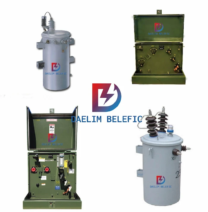
On the other hand, a three-phase power system is utilized for cost-effectiveness, because compared to single-phase transformers, it cost more money to operate and maintain. But in terms of size, single-phase transformers are easier to transport since they have a smaller and lesser weight.
The Three Phase power system is used due to its cost-effectiveness over the Single Phase Transformers. However, looking at the size and the ease for transportation, the Single Phase Transformers are suitable.
Moreover, these are further divided into core types and shell types.
A core type is basically a type of transformer that has both of its windings placed on the side limbs. Furthermore, core type transformers mainly have two magnetic circuits.
On the other hand, shell-type transformers only have one magnetic circuit and winding and they are placed on the central limbs of the transformer.
This type has one magnetic circuit and winding is placed on the central limbs of the Transformer.
Oil-type transformers are basically transformers that use oil as their cooling medium. Moreover, transformer oil or mineral oil is known to be the most effective cooling medium for transformers.
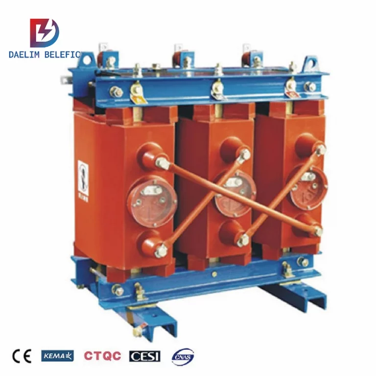
Contrary to oil-type transformers are dry-type transformers, this type of transformer makes use of forced air or pressurized air as their cooling medium. This means that dry-type transformers are not flammable. However, this does not mean they do not have their own advantages and disadvantages.
You might have heard about step-up transformers and step-down transformers which are basically two types of transformers that have the ability to increase or “step-up” the voltage levels from low to high.
Moreover, step-up transformers are of great help when it comes to voltage fluctuations because this type of electrical device is capable of stabilizing the power and supply and distributing them at normal levels.
On the other hand, step-down transformers are the complete opposite of step-up transformers, and they basically step down voltage levels from transmission levels to distribution levels for consumer use (e.g., homes, buildings, etc.)
As the name suggests, indoor transformers are transformers that are safe to operate inside establishments. For instance, dry-type transformers are considered indoor transformers since they can practically be placed inside buildings.
Moreover, they are used for office and residential purposes.
Outdoor transformers on the other hand are transformers that are not safe for indoor allocation, mainly because they are flammable since they have mineral oil or transformer oil inside them, which can easily cause fire and even an explosion if triggered.
A distribution transformer is another type of transformer that is commonly used around the world.
Moreover, these transformers are commonly used for residential and commercial purposes since they have an efficiency level with 50% fill load capacity, and they have the ability to operate for 24 hours as well with an excellent regulation for voltages.
An instrument transformer is a type of transformer that involves current transformers and as well as potential transformers that are commonly used to reduce the voltage.
Moreover, these transformers are capable of providing electrical isolation between high voltage power circuits and as well as measuring instruments.
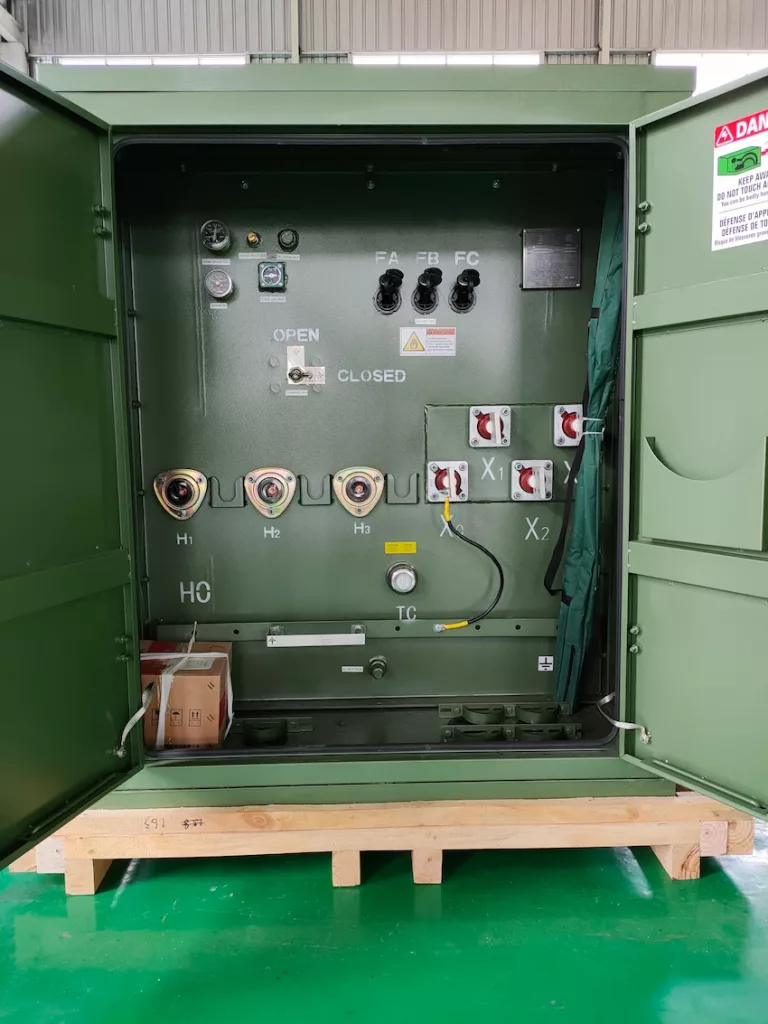
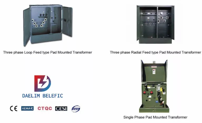
Pad-mounted transformers are basically distribution transformers that are sealed in a metal housing that has a shape of a large locker that is earthed on the ground with a pad sitting beneath it.
This transformer is also considered a public transformer since it is commonly found in public areas and even in front of houses.
Pole-mounted transformers are also another type of transformer that is considered a public transformer since it is safe to be placed in public areas.
However, this type of transformer is mounted on a utility pole, which means that it is an above-ground transformer.
A two-winding transformer is used in applications that depend on the ratio of the voltage. Two winding transformers are known to be used with a ratio that is greater than 2 while the latter is operated at the time of voltage ratio that is less than 2.
An auto-winding transformer is an electrical transformer that only has a single winding. The “auto” prefix refers to the single coil that is acting independently without any automatic mechanism involved.
Autotransformers also have the same winding act, having both the primary and secondary winding sides of the transformer.
Now that you know the different types of transformers, it is time to move on to power transformers and their power transformer diagram.
The main purpose of power transformers is to stabilize power voltage fluctuations which are used during high power load durations.
However, power transformers are not limited to this function only as they too have several functions and abilities.
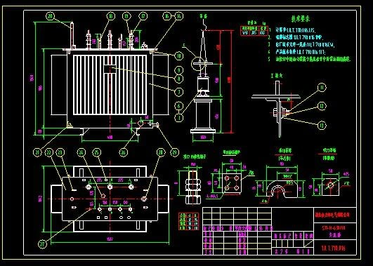
A power transformer diagram is a graphical representation of the various components and connections of a transformer. It is used to show the electrical circuit of a transformer and how its different parts are interconnected.
Transformers are used to change the voltage of electrical power from one level to another. They consist of two or more coils of wire that are wrapped around a magnetic core. The primary coil is connected to the source of electrical power, while the secondary coil is connected to the load.
A power transformer diagram is used to show the different components of a transformer, including the core, the windings, the taps, and the bushings. It also shows how these components are connected to each other and to the power source and load.
Understanding power transformer diagrams is essential for anyone working with electrical systems, including engineers, electricians, and technicians. It allows them to troubleshoot problems, identify faults, and make necessary repairs.
The transformer itself works on Faraday’s law of electromagnetic induction and mutual induction principle. Based on Faraday’s law of electromagnetic induction, this will cause the magnetic flux to change electromotive force in the secondary coil that is associated with the core that has a primary coil.
A power transformer’s diagram involves trading voltages for currents in a circuit while it is not affecting the totality of the electrical power. This means that it will take high-voltage electricity with a small current to change into low-voltage electricity with a large current, or vice-versa.
In terms of the drawbacks of power transformer, there are a few that you should consider before making a purchase decision.
Due to the material of the power transformer’s iron core, there is a slight chance that there will be wastage in the current’s flow.
During the operation, you can expect that the transformer will produce a lot of heat the requires cooling. This will create a break in the flow of the current.
Transformers can indeed be noisy once they start operating.
For instance, dry-type transformers are known to be noisy due to the forced air or pressurized air that is in the transformer that is making the parts of the transformer bang against one another – making metal-clanging noises.
Nonetheless, this should not be a big deal if you have your power transformer placed in a remote location or an area where there are no people, buildings, or houses nearby.
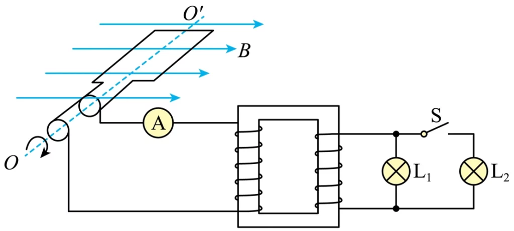
A power transformer diagram is a schematic representation of a power transformer’s electrical connections and circuitry. Reading a transformer diagram is important for understanding the functionality and design of a transformer. Here are some tips for reading a power transformer diagram:
Identify the transformer type: There are several types of transformers, including step-up transformers, step-down transformers, isolation transformers, autotransformers, and others. Each type of transformer has a unique diagram, so it’s important to identify the transformer type before attempting to read the diagram.
Understand the symbols: The symbols used in a transformer diagram represent the electrical connections and components of the transformer. Some common symbols include the transformer core, primary winding, secondary winding, tap, and ground. Understanding these symbols is essential to interpreting the diagram correctly.
Follow the flow of electricity: A power transformer diagram illustrates the flow of electricity through the transformer. The diagram will show the input and output voltage levels, the number of windings in the primary and secondary coils, and any taps or connections between the coils. Following the flow of electricity through the diagram will help you understand the transformer’s functionality.
Pay attention to the phasing: Power transformers may have single-phase or three-phase configurations. It’s important to identify the phasing of the transformer and understand how it affects the voltage and current levels.
Consult the manufacturer’s documentation: Transformer diagrams can be complex and difficult to understand. If you’re having trouble interpreting the diagram, consult the manufacturer’s documentation or seek the advice of a qualified electrical engineer.
By following these tips, you can gain a better understanding of power transformer diagrams and their functionality. Understanding transformer diagrams is important for anyone working with transformers, from electrical engineers to electricians and technicians.
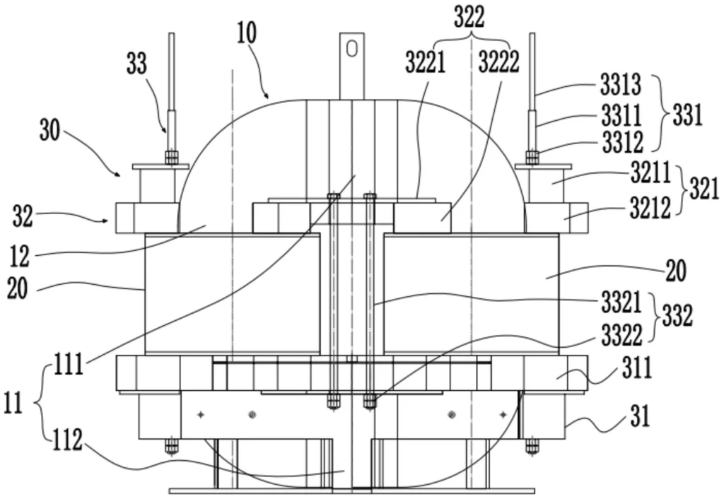
Reading a power transformer diagram can be overwhelming, especially if you’re not familiar with the symbols and terminology. Here are some tips and tricks to help you read and understand the diagram more easily:
Understand the symbols: Power transformer diagrams use a range of symbols to represent different components and connections. Make sure you’re familiar with the symbols used in the diagram before attempting to read it.
Follow the flow: A power transformer diagram shows the flow of electricity from one component to another. Follow the flow of electricity from the source to the load to understand how the components are connected.
Identify the primary and secondary windings: A transformer has two windings, the primary and the secondary. Identify which winding is which to understand how the transformer works.
Pay attention to phasing: Power transformers are often used to change the phase of the electricity. Make sure you understand the phasing of the transformer and how it affects the flow of electricity.
Look for grounding connections: Transformers often have grounding connections that are crucial for safety. Identify the grounding connections and make sure they are properly connected.
Check for voltage ratings: The voltage ratings of the transformer and its components are critical for proper operation. Make sure you understand the voltage ratings and that all components are rated for the correct voltage.
Follow the manufacturer’s instructions: Power transformer diagrams can vary depending on the manufacturer. Always refer to the manufacturer’s instructions and guidelines to ensure proper operation.
By following these tips and tricks, you can read and understand a power transformer diagram more easily, allowing you to troubleshoot and maintain your electrical system more effectively.
There is without a doubt that power transformers are versatile electrical devices that can handle large projects for commercial, industrial, or business use. However, make sure to consider some elements first before getting one (e.g., location, permits, passing standards, etc.)
If you have any questions or clarifications with regards to the power transformer diagram, please do not hesitate to contact DAELIM’s team of professionals for immediate assistance.
When you need to find more than just existing transformers, Daelim’s Transformer Service Center can help you design and produce distribution transformers that meet your unique needs.
We have our own factory and a professional team of engineers, which can design and modify application requirements that meet all your conditions.
Download Resource
ELECTRIC, WITH AN ENGE-- DAELIM BELEFIC
After filling in the contact information, you can download the PDF.