
How to Choose Pad Mounted Transformer?
Table of Contents Selecting the right pad-mounted transformer requires careful consideration of several critical
ELECTRIC, WITH AN EDGE
Loss rate is an important index to evaluate the main transformer, which can not only reflect the quality of the main transformer, but also characterize the accuracy of power metering. For the abnormal loss rate problem in the main transformer power consumption rate data statistics of a power plant, the cause was determined through testing and analysis, and solution measures were proposed.
In recent years, the load rate of power plant units has been reduced year by year, the environmental protection facilities have been renovated and upgraded, and the heating area has increased, resulting in a rising trend in the power plant electricity consumption rate year by year.
Analyzing the data in Table 1, the unit load rate has been reduced year by year since 2017 due to green power consumption and foreign power into Lu. In addition, the desulfurization ultra-low emission transformation increased a large number of 6kV voltage level facilities such as desulfurization circulation pumps, plant electricity consumption increased, power plant electricity consumption rate is on an upward trend. 2019 organization denitrification system optimization operation, significantly reduced the differential pressure of the air preheater, phase I, phase II fan power consumption and powder power consumption decreased by 7% year-on-year, so in the case of 2019 unit load rate reduction, power plant electricity consumption rate did not significantly higher.
From 2016 to 2019, the plant-wide heat supply ratio increased year by year, the demand for external network heat supply increased, and the increase in electricity consumption of the heat supply plant was basically normal.
After 2017, the main transformer losses of the whole plant increased significantly. Calling up the data of recent years, the power of No. 3 and No. 4 units were selected for comparison for 12 moments in the past two years, and it was found that the loss of No. 4 main transformer changed with the high and low load of the unit, and the overall loss of No. 3 main transformer was 1,000kW ~ 3,000kW higher than the loss of No. 3 main transformer, and the loss rate of No. 4 main transformer reached 3-8 times of the loss rate of No. 3 main transformer. If we can find out the reason for the large loss rate of No.4 main transformer and solve it, we can reduce the power consumption rate of the plant and the economic benefit is considerable.
The main transformer loss rate is the ratio between the main transformer loss rate and the unit’s power generation minus the high plant transformer power and excitation transformer power.
Analysis of the main transformer loss rate exceeds the standard, mainly because the transformer itself has problems, or there are errors in the electrical energy metering device. There are three main factors affecting the error of the electric energy measurement device.
(1) current transformer and voltage transformer. According to the “power transformer calibration regulations”, when the primary current changes from small to large, the error of the current transformer relatively from large to small. Even if the primary current changes relatively small, the current transformer will also be in the error qualified range of larger errors, resulting in increased statistical errors of electrical energy. Voltage transformer and current transformer operating characteristics curve is basically the same. As the voltage transformer usually operates under the rated voltage, so the voltage transformer primary voltage of small changes in the voltage transformer error is not significant.
(2) current transformer secondary circuit and voltage transformer secondary circuit. Current transformer secondary circuit breakage, poor contact, will cause the energy meter current reduction, resulting in power loss. Voltage transformer secondary circuit break or contact resistance value is too large, will make the energy meter at the secondary voltage drop exceeds the standard, also will lead to power loss, and then affect the power settlement.
(3)Electricity meter. The accuracy level, stability and working electromagnetic environment of energy meter will affect the accuracy of energy meter measurement.
Power plant production is continuous, and problems can occur at any time. Such as current circuit has a small shunt or voltage circuit voltage drop is too large, etc., will lead to the shutdown power reduction, and is not easy to be detected, the final power plant efficiency will be greatly affected. To solve the problem, we must first find out the problem, grasp the relationship between main transformer loss and power metering, and find out the power metering problem according to the deviation of main transformer loss rate or analyze the main transformer loss rate according to the deviation of power metering.
Check the maintenance records of No.4 main transformer in recent years, all indicators are qualified. Check the electrical test and oil sample chromatography analysis in the past years, no change was found in the main transformer related test data, and the gas composition in the oil sample did not change much. At present, the main transformer No. 4 is operating normally, the main transformer temperature and other parameters have not changed significantly, basically excluding the transformer’s own factors.
The voltage transformer and current transformer of No.4 unit were checked and inspected during the repair time of No.4 unit, and the voltage transformer and current transformer of generator outlet were all qualified, thus excluding the voltage transformer and current transformer from their own causes.
Three times of energy meter accuracy calibration and replacement of energy meters were carried out, and no problems were found.
(1) Measure the voltage, current amplitude and phase detection at the energy meter. Use PEC-H3A three-phase energy meter field calibrator to detect the secondary voltage and current input value of No.4 generator energy meter, No.4 high plant transformer energy meter and No.4 main transformer energy meter, and get the amplitude and phase relationship.
Generator voltage transformer output is normal, the main transformer high-voltage side A-phase voltage amplitude and the other two phases deviation is large.
(2) Main transformer decompressor voltage transformer metering circuit secondary voltage drop detection. In order to ensure data accuracy and avoid instrumentation errors, after replacing the equipment, the secondary voltage drop of the voltage transformer outlet of No. 4 main transformer is measured, and the input voltage is measured again at the voltage transformer local terminal box and energy meter side.
(3) No. 3 main transformer voltage transformer and No. 4 main transformer voltage transformer amplitude comparison. Measure the measurement winding of the voltage transformer of No.3 main transformer and the voltage transformer of No.4 main transformer.
(4) Check the relevant metering circuit equipment parameters. In order to ensure that there is no problem with the calculated data of energy meter, check the parameters of relevant equipment of No.4 unit again.
Through the inspection, no error related to the electric energy error was found in the excitation transformer of Unit
(5) Compare the power data of Unit 3 and Unit 4 for the same period. According to the power difference as the generator power minus the sum of the power on the high voltage side of the main transformer and the power on the high voltage side of the high plant transformer, 12 sets of data between April 2018 and March 2020 were found in the integrated system, as shown in Table 6.
Through the data calculation, it was found that the losses of Unit 4 varied with the high and low unit load during normal operation of the unit, which was 3 to 8 times higher than that of Unit 3 during the same period.
(6) Testing the power parameters on the high-voltage side of excitation transformer No. 4. In order to thoroughly grasp the power flow, the power parameters on the high-voltage side of excitation transformer No. 4 were tested, and the data are shown in Table 7.
The active power of the unit is 270.43MW, the reactive power is 155.82Mvar, and the excitation current is 1,951A. The voltage phase on the high voltage side of excitation transformer No.4 is 120.6° between phases AB, 119.4° between phases BC and 119° between phases CA.
The calculated active power of excitation transformer No. 4 is 749.39kW and reactive power is 2,313.04kvar.
Through this test, for the first time in the whole plant, the power consumption data of the excitation transformer was grasped through the test, and the active power, reactive power and power factor of the excitation transformer were verified. Through the power balance analysis, it was confirmed that the power consumption on the low voltage side of No. 4 main transformer was still large.
(7) No. 4 main transformer high-voltage side voltage transformer inspection. The test data of the voltage transformer on the high-voltage side of No. 4 main transformer before and after February 2017 were compared, and no abnormal data were found. In order to exclude the problem of internal overheating in the operation of the voltage transformer, the voltage transformer on the high-voltage side of No. 4 main transformer was subjected to infrared imaging and compared with conventional imaging, as shown in Figure 1.
-768x437.webp)
From the field observation and imaging images, no poor top contact and internal overheating problems were found.
No. 4 main transformer has not been altered in the power meter circuit since it was powered on September 10, 2015, during which the power meter was only replaced on September 19, 2016. According to the statistics, after February 15, 2017, the loss of No. 4 main transformer began to increase, so the reason for the increase of loss is not the voltage transformer secondary circuit voltage drop is large.
Through the power meter calibration, no problems with the meter were found. Through the excitation transformer power test, it was found that when the unit load was 270.22MW, about 1.5MW of active power was not known to go.
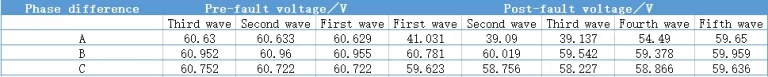
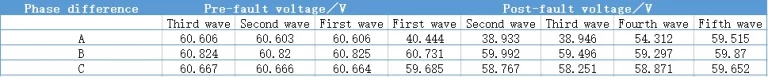
After retrieving the data of recent years, it was found that the loss of No. 4 main transformer increased significantly after February 15, 2017. on February 15, 2017, the operation of No. 4 unit was as follows: at 10:09, 220kV Wanjiu II line tripped, high-frequency distance protection operated, accelerated tripping after reclosing action, 220kV section IIB bus differential protection operated and tripped, all lines and devices on this bus tripped Unit 4 tripped; the reason for the inspection was the breakdown of phase C gas chamber of 217-2 disconnecting switch of Wanjiu II line, and the ⅡB section bus was turned to overhaul; at 18:18, Unit 4 resumed operation at the ⅠB section bus. At the time of the accident, the voltage of the voltage transformer on the high-voltage side of the main transformer of No. 3 and No. 4 is shown in Table 8 and Table 9, respectively.
Checking the records, the voltage of the voltage transformer on the high-voltage side of No. 4 main transformer on November 14, 2017 had a significant deviation, see Table 10.
Combined with the above data, No.4 main transformer loss rate increase is a fault occurred after the main transformer voltage transformer secondary circuit problems, meter measurement is not allowed, the only explainable reason is the voltage transformer ratio there is a large error.
In order to test whether the A-phase voltage error of 204-PT voltage transformer on the high-voltage side of No.4 main transformer has an equal impact on the loss of the main transformer, the original electric energy metering system energy meter and the shut-off metering energy meter will be tested for data comparison. 204 circuit breaker of No.4 main transformer is on 220kV section IIB bus, the voltage of section IIB bus voltage transformer should be connected to the newly added Electricity meter, keep the current circuit with the original power meter current circuit.
Considering that the busbar voltage transformer accuracy is 0.5 grade, the voltage is provided by the 0.2 grade voltage transformer of ⅡB section busbar at the nearest interval of 2.18 million nine Ⅱ lines.
In order to ensure the validity of the data, the test duration is 70h, and each energy meter is calibrated again before the test to ensure the nominal accuracy of the instrument. The electric energy data of unit 4 was obtained through the test, see Table 11.
In the test, the total loss of main transformer gate meter is 142.240MWh, and the total loss of electric energy metering system meter is 61.984MWh. From the data, the main transformer gate meter is 1,147kWh more loss per hour than the electric energy metering system meter.
Through the calculation and comparison of variable loss, the main transformer loss rate was reduced from 0.762% to 0.332%, a reduction of 0.43 percentage points. Through the comparison test, it was confirmed that the low voltage of A-phase of 204-PT voltage transformer on the high-voltage side of No.4 main transformer was the main reason for the large loss rate error of No.4 main transformer.
After the test again on the No. 4 main transformer high voltage side 204-PT voltage transformer three groups of voltage measurement, the data are shown in Table 12.
According to the A-phase voltage is lower than the normal value of 1.5V calculation, verify the average value of the high-voltage side current is 2.975A, the power factor is 0.88, the preliminary calculation of power error is 2073kW.
From the data, in addition to the star connection A-phase voltage is low, open delta connection A-phase voltage is also slightly low, three groups of secondary voltage are low, only when there is a fault in the primary winding of the voltage transformer, it will cause three groups of secondary voltage are low, again accurately locate the voltage transformer fault problem, and with the voltage transformer grounding, secondary voltage drop, energy meter, primary equipment are not related.
Thus, through the test, it is verified again that the low voltage of A-phase of 204-PT voltage transformer on the high-voltage side of No.4 main transformer is the main reason for the large calculation error of No.4 main transformer.
Through the current tests and trials, it can be judged that the main transformer does not have the problem of loss increase, and the main reason for the abnormal loss rate of the main transformer is the low voltage of the A-phase of the voltage transformer on the high-voltage side of No. 4 main transformer.
No. 4 main transformer energy meter is not the settlement energy meter of the power supply of the oil production plant, but the energy meter of the oilfield assessment of the power supply of the oil production plant.
Replace the voltage transformer, need a long procurement, construction cycle, is bound to have a considerable impact on the operating performance of the oil production plant, should take other ways to solve as soon as possible. As the main transformer voltage and bus voltage are the same, in the power comparison test, the way of changing the voltage circuit is taken.
Based on this, the voltage circuit of No.4 main transformer energy meter can be changed to busbar voltage circuit. The accuracy of busbar voltage transformer is 0.5 grade, although it does not meet the technical requirements of trade metering, but still can reduce the power loss.
No.4 main transformer energy meter is the asset of Dongying Power Supply Company, and the electricity data has been teleported, so it cannot be changed at will. In this regard, we negotiated with Dongying Power Supply Company for many times, and explained that changing the voltage circuit wiring of No.4 main transformer energy meter has no effect on the settlement of power supply between the two sides, and finally Dongying Power Supply Company agreed to change the voltage circuit wiring of oil extraction plant.
The team applied for the work ticket and changed the input voltage of 220kV side energy meter of No.4 main transformer from 204-PT voltage transformer to 220kV section IIB bus voltage transformer secondary first group voltage.
One month after the wiring change, the loss rate of the main transformer was reduced from 0.45% to 0.28%, with obvious effect. Through the implementation of this solution, the main transformer No. 4 will be increased by 2.5 million kWh to 30,000 kWh of electrical energy assessment per day, with obvious economic benefits.
For the problem of abnormal transformer loss rate, it is recommended to check the three-phase amplitude of the secondary voltage of the main transformer voltage transformer. For the existence of the main transformer voltage transformer secondary voltage repeatedly measured have a large deviation in amplitude, it is recommended to use the downtime to check and qualitative test. At present, there is no suitable test instrument in the oil production plant to carry out the characteristic test of ratio and angle difference, etc. Consider introducing external test units to carry out the characteristic test of ratio and angle difference on the main transformer voltage transformer, so as to get accurate data.
At the same time, it is recommended to conduct comprehensive testing of the booster station, especially the second phase of the regional grounding network. According to the current main transformer voltage transformer secondary voltage A-phase low problem, in addition to voltage transformer characteristics test, combined with other busbar action and segmentation circuit breaker unexplained action, check whether the voltage transformer area of the booster station voltage transformer large grounding network is good, voltage transformer grounding resistance data is qualified.
On the other hand, the implementation of the measurement of the voltage transformer secondary grounding point problem. If the voltage transformer ratio is not a problem, then consider the neutral point drift problem.
Download Resource
Table of Contents Selecting the right pad-mounted transformer requires careful consideration of several critical

The primary function of the pad mounted transformer is to serve as a critical distribution

A pad mounted transformer operates through electromagnetic induction, serving as a crucial distribution component that
After filling in the contact information, you can download the PDF.