
How to Choose Pad Mounted Transformer?
Table of Contents Selecting the right pad-mounted transformer requires careful consideration of several critical
ELECTRIC, WITH AN EDGE
Due to the frequent changes in charge resistance and raw material grade, electric arc furnace transformers must have more voltage regulation stage.
They should also have a small output voltage difference per stage, a large voltage regulation range and a low low-voltage. If the current increases, it is more severe and the impedance of the short wire is greater.
The submerged arc furnace’s power imbalance is often related to the shortwire structure, charge uniformity and electrode position, as well as other factors.
The electric furnace equipment’s short net refers to the length of the wire from the low voltage side to the electrode. This line runs approximately 10m to 20m in length. The electrode’s triangle is connected to the short net. Because of the differences in lengths between the bus bars, mutual and self-inductance for each phase is the same. The three-phase electrode power does not equal the voltage or current on the secondary side. The three-phase impedance imbalance causes this three-phase power imbalance. Yes, the net length of the intermediate phases is very short. The inductance is also lower than the other phases. Therefore, the power and impedance are small.
The “enhanced” phase is one with high power, while the phase with low power is another. Three things are likely to cause electrode accidents: 3 the shape and position of the crucible are altered; 4 the furnace’s lining is damaged; 5 uneven heating of molten pools will result. It is possible to use a single phase group in large-capacity electric furnaces.
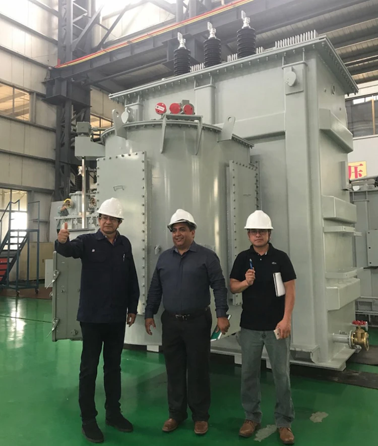
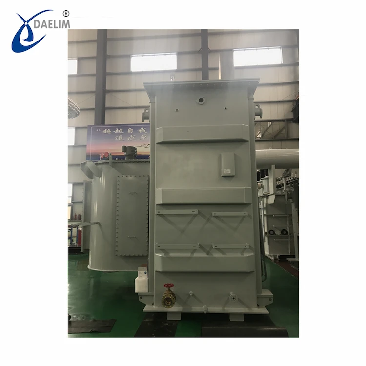
Daelim Belefic is a professional transformer manufacturer with over 15 years of experience in transformer design and production. Daelim has a professional team of designers who will connect with you throughout the technical process to ensure the quality of every transformer you purchase. At the same time, Daelim can also provide you with high impedance furnace transformers, DC electric arc furnace transformers, ladle refining furnace transformers, and submerged arc furnace transformers. A variety of transformers can fully meet all your needs for electric furnace transformers.
At the same time, Daelim Belefic has also obtained a number of product certifications such as ANSI, IEEE, IEC, DOE, CS, etc., to ensure that each transformer you purchase can perfectly meet the industry requirements of your country.
Three-phase short grids have equal length. However, the production cost for three single-phase transformers are much higher than those of three-phase transformers of the same capacity. Therefore, it is cheaper to use three phase sub-adjustment of electric arc furnace transformers having a capacity of 16000kVA 25000kVA. This reduces the impact of three-phase imbalance. Users have approved the following.
Transformer model: HTSSPZ-22000/110.
Capacity: 22 000kVA. Long-term overload 30%.
Cooling method: OFWF (strong-oil water cooling).
110kV is the primary voltage.
Secondary voltage: 220/155/50V (220/155V constant current, 155/20V constant current)
Voltage regulation mode: 35 level on-load voltage regulation, or split-phase voltage regulation.
The range isn’t too big at level 5) Linking group: Ynd11
Impedance voltage (lowest secondary voltage): 56%
It is not recommended that the “rated capacity + long term overload percentage” be mentioned. For an electric arc furnace transformer with one specification, it is not recommended to mention the “rated capacity”, but rather a “load regulation”. The load cycle curve is made up of multiple rectangles. This load cycle curve encapsulates the maximum load required by the electric furnace during each smelting period. It allows for the calculation of the equivalent load current when the load changes frequently.
The winding time constant is 5-10 minutes and it takes only 20-30 min to achieve stable temperature rise. Therefore, the maximum load current should not be used to calculate temperature difference between winding copper oil and OF cooling methods. It takes 6-7 hours to reach stable temperature rise. The equivalent load current can be used to accurately reflect transformer loss during the cycle. This is equivalent to the effect that the constantly changing load has on the average temperature increase of the oil.
The equivalent load current can be used by an electric arc furnace transformer to select the cooler’s capacity.
A 90 MVA steel-making furnace transformer’s smelting system is the following: 0-10 minutes is rated current IN; 11-35 mins is 1.2 IN; 36-40 mins is 1.1 IN; 41-45 mins is IN, 46-45 mins is IN, 46- 50 mins is 0IN (intermittent among two furnaces). You can choose a cooler of 2×400 kW according to the equivalent load current. However, it is not necessary to choose a cooler of 2x500kW according to 1.2IN.
Many transformer accidents are caused by incorrectly selecting primary voltage values. The connotation of the primary voltage of different types is also different. The output voltage of a power transformer is set constant. However, there are often large voltage adjustments at once, such as +-8×1.25%.
This ensures that the voltage fluctuation is kept within +-10%. The core magnetic flux, as well as the voltage per turn, remain the same through the adjustment in the number of primary winding turns. The opposite of the power transformer is the electric arc furnace transformer. It sets the primary voltage constant and adjusts the output voltage depending on the needs of the melting process.
For furnace transformers other than direct voltage regulation (such as those using series transformers or pre-autotransformers), if the primary winding is not tapped, and the primary voltage is not properly set, the transformer may suffer unacceptable overexcitation. Overexcitation can lead to many problems. First, the no-load current change rate di0/dt will increase and the interception voltage will rise.
Second, the excessive zero-sequence potential generated when three-phase loads change asymmetrically or dramatically will invariably cause metal structural parts of the load to discharge (it might be a small gap, or poor contact). This causes the characteristic gas from oil decomposition, which penetrates the oil. middle. Manufacturers may be confused as to why certain products have acetylene and other oils.
Sudden electrode load loss is a common phenomenon in steelmaking electric furnaces.
This is similar to the load rejection of generator Transformers. The greater the severity of overexcitation, the more the load dump voltage will rise, and it will have a much higher maximum value than a power transformer. Analyses have shown that electric arc furnace transformers don’t have the ability adjust overexcitation as power transformers.
They can only rely on a slightly lower magnet density in the design. A low magnetic density will invariably lead to cost increases and load loss.
The furnace transformer will be damaged if it is subject to severe overexcitation. Therefore, the primary voltage should match the furnace transformer’s maximum voltage.
The no-load maximum overvoltage must not exceed 5% of rated voltage. The higher value should remain within the voltage regulation range after the front-step-down transformer has taken into account other loads.
If the user insists that the electric arc furnace transformer must have 10% overexcitation ability, then the core magnetic density should be approximately 5% lower than the power transformer. However, the cost and load losses will increase. Otherwise, it will be very difficult to ensure safe operation.
It is important to extend the secondary voltage range as required by the smelting process correctly. However, if it is not, it can be counterproductive.
The common voltage that operates at a different position from the secondary highest will cause the short-circuit resistance of the actual furnace operation to increase. This will result in a decrease of the furnace’s output power. Users often describe furnace changes as “vigorous” and “boring”. This is due to the three-phase impedance imbalance and excessive short-circuit reactive energy. It is also dependent on the working position of common grade.
Blindly increasing the secondary voltage adjustment range will not improve the output power of transformers or reduce the product’s manufacturing cost.
The shorter the short-circuit resistance, the better it is for reactive power reduction and voltage regulation.
The short-circuit current multiplier is proportional to the short circuit impedance. The short-circuit will cause the winding to experience a severe electrodynamic shock, and a high winding temp. It is desirable that the furnace transformer has a high Q impedance to reduce the short-circuit current.
Core transformers will have a higher manufacturing cost if they are too low or too high in impedance.
Current situation: The short-circuit impedance for electric arc furnace transformers that have large short-circuit possibilities is lower than that of power converters that have small short-circuit chances.
The standard short-circuit impedance value for a 110kV power transformer is 10.5%. Double-winding power transformers use high-impedance transformers with short-circuit impedances of 10.5%, 12.5%, or 14.5% to increase the reliability of urban power supply. The reliable operation of the city network transformer is assured by the values of 16.5%, 23%, and 23%.
Different electric arc furnace transformers require different short-circuit impedance requirements.
The ultra-high-power electric-arc furnaces use long-arc operation. Their natural power factor is very close to 0.866. To stabilize arc combustion, the short circuit impedance of the steel making furnace transformer at the secondary maximum current must be approximately 8%. An additional series reactance may also be required. To maintain the cosph in the main circuit between 0.75 to 0.85.
It is possible to easily ensure the short-circuit resistance for steel furnace transformers. The submerged arc furnace has a short-circuit resistance standard of 110 kV calcium caride furnace transformer at secondary maximum voltage of 6% to 8.8%. Yellow phosphorus furnace transformer is between 7% and 9%.
Many users choose to have a low short-circuit resistance. Some even insist that the impedance at the lowest secondary power voltage be about 6%. This means that the impedance at higher secondary voltages is only 3% to 4. This is why there is an odd phenomenon. It is common for the transformer of a steelmaking furnace to have a normal working short circuit. However, it is quite common for the transformer of a submerged arc furnace to be damaged with very little fluctuation in the electrode current.
It is obvious that pursuing the low impedance furnace transformer is not worth it. The capacitor compensation can completely compensate for the reactive power increase by increasing the short circuit impedance.
According to the author, the secondary highest voltage of the submerged furnace transformer’s short-circuit impedance, should be set at the higher limit in the applicable standard. This will ensure that the short circuit resistance of the winding is easily guaranteed.
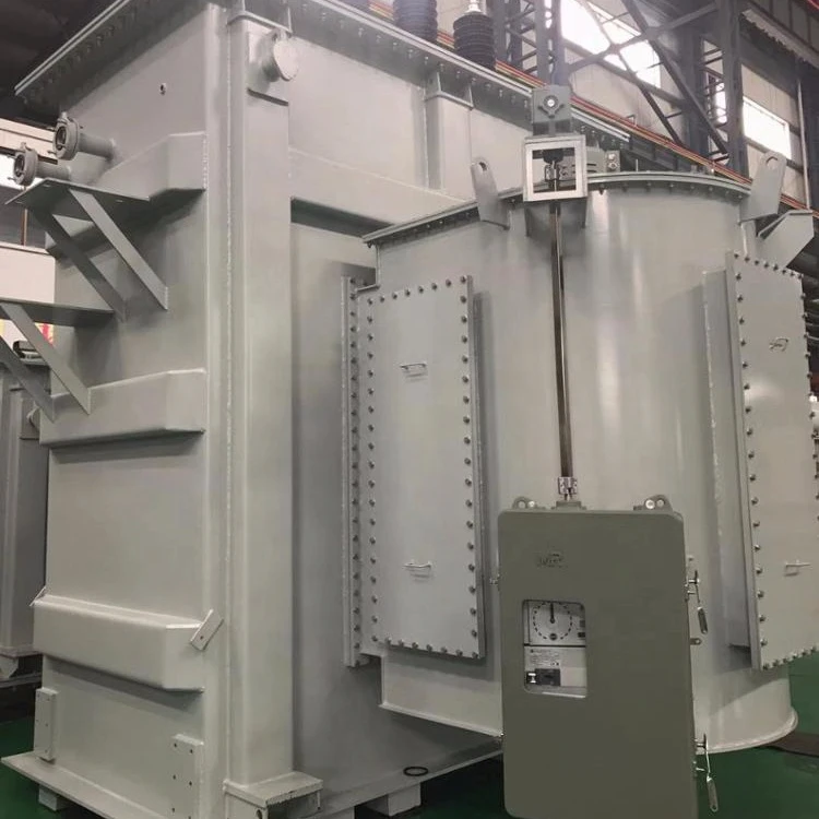
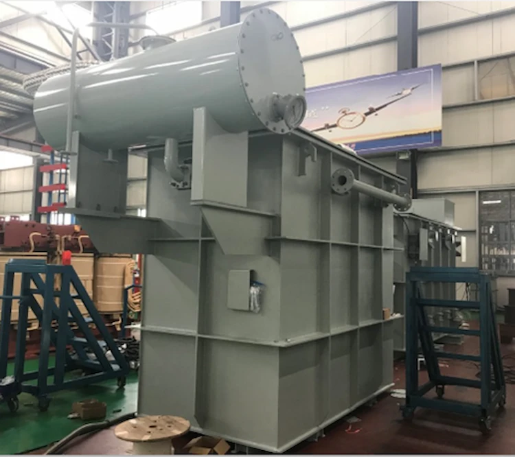
Features of the product structure:
(1)The secondary voltage, which is very low, is not required for voltage regulation. Therefore, the voltage regulation method using a series transformer is chosen.
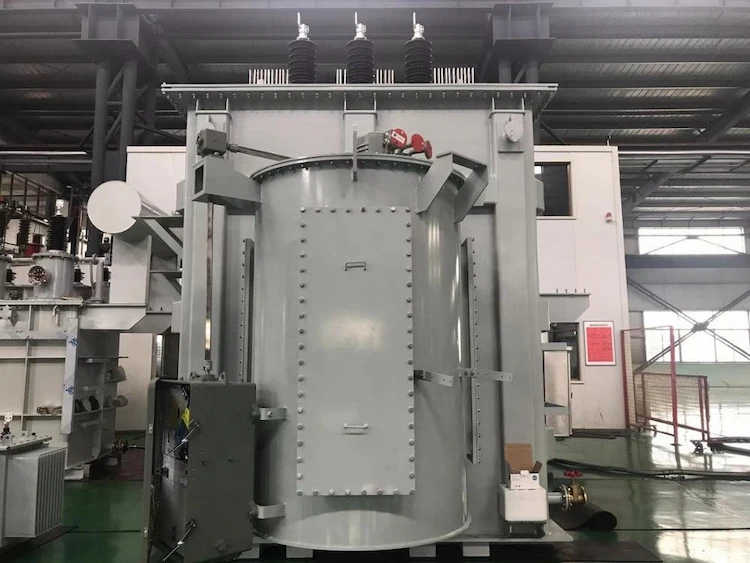
(2)Split-phase voltage regulation. The main is a three phase five-column, iron core. They share an oil tank. Secondary terminals cross each other using water-cooled copper tubes.
For the three phases A, B and C, three single-phase switches will be used. Each phase can adjust the voltage independently to compensate for the power imbalance. Each phase winding of an electric arc furnace transformer will operate under different taps.
This means that each furnace phase will work at the highest voltage, current intensity, and power of the molten pools.
The process of voltage regulation is complicated because the number of turns on the series-transformer low-voltage windings is fixed and the voltage applied changes to them. Therefore, the series transformer belongs the variable magnetic flux voltage regulator, while the main transformer the constant magnetic flux regulation. The series-transformer high voltage windings will have different voltage values. The magnetic flux is proportional. Small.
Split-phase voltage regulation causes the three-phase circuit of the series Transformer to be unbalanced. The three-phase unbalanced magnetic flux does not only destroy the three-phase symmetrical negative-sequence and positive-sequence components, but also has the exact phase and equal-sized zero-sequence components.
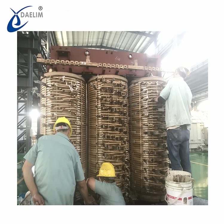
To overcome the magnetic circuit’s imbalance, iron cores with different magnetic flows of each phase are divided into five columns. The purpose of these columns is to allow zero-sequence magnet flux to flow through the middle three columns.
Side yokes are the columns that form the difference magnetic flux in the magnetic circuit. The section of the iron yoke of the five-column core iron with an asymmetric three phase magnetic circuit will exceed 1/3. Its side yoke will be mainly divided according to the maximum voltage of the phase regulation.
(1)To monitor the secondary current, a transformer is placed on the tertiary end.
(2)Low-voltage windings should be considered, as well as series transformer high-voltage windsings. Outgoing copper bars, secondary terminals and switches should all be taken into consideration.
(3)The three-phase sub-adjustment has the following advantages: the series-variation adjustment saves material when compared to the direct modulation. Furthermore, the series-variable capability is smaller than the transformer’s rated capacity. The five-pillar side of the yoke has a small amount. Voltage regulation range determines the capacity of the main transformer’s tertiary winding. Its capacity is lower than the transformer’s rated capacity.
(4)A sub-adjusting transformer of this type should not complete the D connector near the secondary terminal in an oil tank, or outside it. To limit the circulating current, it is necessary to connect the electrode to the D connector.
(5)The circulating current in secondary delta connection group limits the output voltage difference between the two phases of the transformer of split-phase regulated piezoelectric oven. The circulating current should not exceed 20% in general.
(6) The power output is between 16 500kVA to 25 000kVA. Phase-split voltage regulation compensates for the three-phase imbalance.
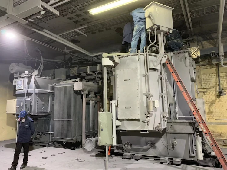
The electrode had been separated from the slag and there were no external factors that could cause a short-circuit before the electric arc furnace transformer failed.
It was discovered that the transformer core had been pulled out and that there were two short circuit fault points.
This was due to insulation damage in the voltage-regulating section of B-phase winding.
Our factory’s 6300KVA electric arc furnace transformer can only achieve a maximum of 3000KW when it is actually used. Overloading cannot cause transformer damage.
The windings work normally and are protected from moisture. March was a dry month with low ambient humidity.
Core pulling revealed no problem at the joint. The contacts of the B phase on-load Voltage Regulator Switch were burned when it was checked.
The accident occurred in March and there were no lightning waves or thunder storms at the time.
The power outage of an electric arc furnace transformer serves two purposes: to lower or replace the electrode. The on-site inspection found that the electrode is not in direct contact with the slag surface. Therefore, power transmission with load cannot be considered.
The gear was not adjusted prior to the power outage. It was set to the required 18th gear when power was restored, so it didn’t need to be adjusted.
Short-circuit resistance: The load current, in addition to causing load losses, also causes a voltage drop within the windings. This means that the output voltage for the transformer when it is loaded is lower than its no-load voltage. The impedance voltage is the voltage drop in the winding. It is expressed as a percentage to the constant voltage. The impedance voltage comprises the voltage drop component of the equivalent resistance that corresponds to the load loss, and the voltage drop portion on the leakage reactance that corresponds to the leakage flux coupled with the winding. These two components are not easily separated. However, the values of these two components cannot be measured separately after they have been measured for load loss and impedance. They are then calculated separately.
The load loss, impedance, and short-circuit impedance are determined by applying a current of approximately sinusoidal waves to one winding (usually the one with higher voltage in the test group of windings). The winding is then short-circuited using a conductor of sufficient cross-section. The power supply voltage is slowly increased until the winding can flow the rated current. The power input to the transformer at this point is the load loss for the pair windings. The voltage applied to excitation winding is Line voltage. This is the impedance voltage. It is expressed in ohms/phase and is called short-circuit impenetrance. A factory experiment was conducted to determine the impedance after the transformer had been repaired.
The measured impedance value indicates that the greater the number of gears, the lower the impedance. The Y-type connection method is more impedant than the D-type. The actual use situation is that the electric arc furnace transformer in our factory is an electric arc furnace transformer. However, high voltage is required for the process. Therefore, the D-type high-voltage connection method is used.
The electric arc furnace transformer must be turned off at least twice a day due to process and production requirements. It is difficult to maintain a stable voltage for long periods of time when there are frequent power outages or low impedance.
Power off the transformer in each gear during the transformer test. 1st gear, 5th gear, 10th gear, 18th gear. Test results showed that the high voltage side current doesn’t fluctuate when the first gear closes, but it fluctuates when the fifth gear closes. The high-voltage current fluctuates a lot when the 10th gear is shut, while the high voltage side current fluctuates a lot when the 18th gear closes. The transformer is most affected by low-speed gear closing.
It is therefore mandatory that the 5th gear be used whenever the power is turned off. The impedance of 1st gear is only 1.1% lower than that of 5th, so the 5th is chosen.
The on-load-voltage regulator switch is used to adjust the gear of the electric arc furnace transformer. This means that the voltage gear on low-voltage can be adjusted while the transformer is operating. So, can the onload voltage regulator Switch be used for frequent shifting?
The V-type onload tap-changer can be used for three-phase neutral point voltage regulation. It is suitable for single-phase 350A rated through current, voltage 35110kV, frequency 50Hz, and bell jars or boxes Top-mounted oil-immersed power.
During operation, the on-load voltage regulator may be moved.
Is the single-phase or three-phase current less than 350A for shifting on load? The impact of shifting gears should not be less than the power outage impact. The impact of shifting gears with loads is the same as that of power outages. The high-voltage coil windings are subject to a large impact. In other words, the current and voltage will be greater than the rated value. 33.5 times the voltage (and between 105KV and 122KV).
This could cause the transformer to fail and wind up in a dangerous condition. It is obvious that the electric arc furnace transformer should not be moved when it is unloaded. This will minimize the damage to the coil and transformer. The voltage-regulating section coil of the electric furnace is slowly energized during shifting. Once the gear has been reached, the required voltage can be achieved.
Maintenance and frequency of use of the onload voltage regulator switch. The power supply must be shut off 3 times per day. Each time the power cuts, the gear position is 15. The on-load regulator switch must be moved 10 times between the 5th and 15th gears during power transmission. Once the power is turned off, the onload voltage regulator switch can continue to operate 20 times per hour.
60 actions are required for power outages 3 times per day. 21,900 movements are required for every day of the year. The manufacturer’s manual provides empirical data that shows the switch can be activated between 100,000 and 150,000 times. After a certain period of use, it is recommended that the tap-changer should be replaced.
Core-pulling maintenance is recommended for the onload voltage regulator. It is important to check the contacts and replace any damaged parts so that it can function normally.
The three electrodes can only be used in conjunction with each other because they are manual operated. The transformer will lose its phase if two electrodes are placed in the furnace at the same time. The operator must place one electrode first, then the two other electrodes simultaneously. Within 10 seconds, the other electrodes should be placed.
To ensure insulation of both the high-voltage and low-voltage sides of the electric arc furnace transformer, it is essential to inspect and maintain the vacuum circuit breaker and high-voltage vacuum circuit daily. Every year, a comprehensive test is done to assess the condition of the transformer. The core-pulling inspection should be performed and the maintenance of the transformer should not be overlooked if the standard is not met.
The electric arc furnace transformer test’s purpose is to determine if the transformer performs according to the applicable standards and technical conditions. It also checks for any defects that could affect normal operation (e.g. short circuit, open-circuit, overheating, etc.). ).
You can also analyze the test results to determine the direction for improving or improving your operation’s quality.
Testing the oil samples from electric arc furnace transformers is done on a quarterly basis. Transformers are tested every year. Tests include: Transformer ratio, insulation performance, applied high voltage, induced high-voltage, and coil DC resistance.
The transformer ratio is important information for parallel operation of electric furnace converters. If the transformer ratios of small and medium-sized transformers differ by 1%, then a circulating current of 10% may be generated following parallel connection. The error in the transformation ratio should therefore be minimized. The transformation ratio experiment will allow you to determine if each phase and the voltage of each gear is constant.
Insulation performance tests are used to determine the insulation condition and decide whether to continue operating or put it into service. R60” refers to when a DC voltage is applied to the insulation material. A weak current will flow through it, which consists three parts: absorption current, charging current and leakage current. The charging current quickly disappears, then the absorption current slowly decreases to 0. Finally, the leakage potential stabilizes, which can be stabilized at that level within 60 seconds. The quality of insulation can be judged by the leakage current, the degree of overall dampness/insulation dampness, insulation surface contamination and insulation defects.
The energy lost to the medium due to dielectric loss is proportional the square of applied voltage, the frequency of voltage and the tangent to the dielectric loss angle. The relative amount of medium loss is represented by the tangent of medium loss angle.
The tangent value for the dielectric loss angle, which can be sensitive to overall defect and voltage, can show the state of insulation under certain conditions. It is important to determine the insulation’s quality by assessing its tangent value.
Download Resource
Table of Contents Selecting the right pad-mounted transformer requires careful consideration of several critical

The primary function of the pad mounted transformer is to serve as a critical distribution

A pad mounted transformer operates through electromagnetic induction, serving as a crucial distribution component that
After filling in the contact information, you can download the PDF.