ELECTRIC, WITH AN EDGE
With a vast market with countless transformers available, it can be confusing for beginners to make the right purchase decision.
Especially considering how close the performance of 4500 kVA Transformers is from its competitors. In this article, you will also be able to learn about everything you should know about 3 phase pad-mounted transformer specifications and residential pad-mounted transformers.
With the demand for electrical transformers continuously rising, it is no surprise that one of the most efficient transformers, the 5000 kVA transformer, is in high demand due to the convenience that the 5000 kVA transformer specification and 5000 kVA transformer weight offers. In fact, you would even be surprised if you convert 5000 kVA to amps.
With the help of DAELIM, a company that has been manufacturing 5000 kVA transformers for decades, you will be able to grasp the full knowledge of what this type of transformer is capable of.
Speaking of the different types of transformers, it is important to discuss them as well. Specifically Dry-type transformers, hermetic transformers, and conservator transformers.
The reason why you should learn about these transformers first is to not confuse you when you are about to learn the characteristics of 5000 kVA transformers.
With the help of DAELIM, a company that has been sharing its expertise and services worldwide about transformers, you will get to know more about this type of transformer, and if you should consider getting one for your business or cryptocurrency mining.
But before going through the complex characteristics of 4500 kVA Transformers, it is highly recommended that you take the time to learn or review the basics and fundamentals of how a transformer works first.
Looking into the different types of transformer’s components, including but not limited to the core, windings, bushings, gas relay, temperature thermometer, breather and many more will help you understand better the components of the 5000 kVA transformers and as well as the 5000 kVA transformer specification as well.
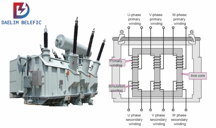
The Core of the transformer is also known as the transformer core.
Normally, transformer cores have three limbs, three limbs usually mean that they are known as a three-phase transformer.
The top and bottom parts of the core is labeled as “yoke”, and the three pieces of the pillar are known as the transformer’s “limbs”
Each limb has a relationship to a specific phase of the transformer, the core itself is secured together with the help of adhesive or heavy-duty straps, on the bottom part, in between the limbs, you will actually see three heavy-duty straps or more.
There are heavy-duty straps securing the lower components in between the limbs.
This goes to say that the transformer’s core is securely clamped together, and the reason behind this is that the core is not one solid structure of the metal.
In reality, these are actually solid sheets that are being fastened together.
These sheets are called laminated steel sheets.
On the sides of the limbs, you will be able to see that there are straight lines that indicate that the sheets are of different geometry, and as you have clamped together, you will get a wavy pattern, You will also be able to see this on the other limbs as well.
Take note that the transformer’s core is not actually cylindrical.
The reason behind why the sheets are being fastened together is to mitigate the hysteresis and the eddy current losses.
This means that you will have to clamp the metal sheets together to form a certain shape of a limb.
Fastening the pieces of metal sheets to form the yokes is part of the process as well.
Each of the sheets is actually insulated from the other sheets.
The reason why this is done is to totally isolate or insulate each piece of metal sheet to achieve the reduction of the eddy current and as well as hysteresis losses.
In the case that there is an electrical current flowing through the windings, and each of the windings is being wrapped around my limbs will result in generating a magnetic field, which in return will make the core magnetized.
This is how all three-phase transformers work including three-phase 5000 kVA Transformers.
The basic function of the core is to direct a specific magnetic field to achieve a high magnetic field density or also known as a “magnetic flux”.
Basically, that is what the core is performing or operating.
In summary, three-phase transformer cores have three limbs, 2 yokes, and the core itself consists of very thin steel laminations that are fastened together, and have been isolated from each other through a coating of lacquer.
After all of these are together, that is what forms a transformer core (three-phase transformer cores).
The rest of the components of the core are just basically for holding the core in place.
There are components that secure the core at the bottom to ensure that the core will not be moving around during the operation and there are security components at the top as well. This also stops the movement of the core and the transformer casing.
This type of core is applicable to dry-type transformers, hermetic transformers, and conservator transformers.
In terms of the design, it really is not that noticeable unless you are using a single-phase transformer instead of a three-phase transformer.
Imagine a dry-type transformer, as you know, this type of transformer does not use any type of liquid to cool itself such as mineral oil, transformer oil, synthetic oil, biodegradable oil, etc.
Dry-type transformers or also known as cast-resin dry-type transformers usually have wheels on the bottom for convenient moving.
Moreover, you will also see a platform on the bottom part of the dry-type transformer, and this platform is used for cooling.
On the back part of the transformer’s enclosure, you will be able to see the connections of the transformer.
Inside the dry-type transformer, you will be able to see a lot of components, including the core that was discussed above.
Looking into the core, you will be able to see the straps that were mentioned earlier. Again, the function of these straps is to keep the limbs together.
On the top of the transformer’s enclosure, you will be able to see the low voltage connections that are coming out of the top part of the dry-type transformer.
Keep in mind that one limb is equal to one phase, since there are three limbs in a dry-type transformer, they are also considered three-phase transformers.
Within the set of protective cylindrical enclosures, each of which can have low voltage windings and high-voltage windings.
The low-voltage windings are expected to be applied closest to the core.
Basically, they are going to wrap around to the core in close proximity.
After the low-voltage windings are being applied, the high-voltage windings are expected to follow.
Now that the primary and secondary windings are installed, the insulator and other cylindrical components will follow.
At the back part of the dry-type transformer (assembled), you will be able to see what type of wiring is being utilized. The windings are usually made out of copper or aluminum.
In the case of using aluminum, they are commonly used if there is not enough space.
So, if you do not have the luxury of space for your projects such as crypto mining or other small businesses, you may use aluminum-type transformers since they are significantly smaller than transformers that use copper.
For copper windings, it is expected that the conductivity of copper is higher compared to aluminum.
Moreover, copper windings are capable of carrying higher currents. But in terms of price, of course, aluminum transformers are significantly cheaper than copper ones.
If you have the space for copper transformers, DAELIM strongly suggests you go for them because they are considered more efficient.
Keep in mind that low voltage windings are supposed to be wrapped closely to the core while the high voltage windings are wrapped 2nd to the low voltage windings then assemble everything to their respective places.
The windings can either be made out of copper or aluminum and put everything in place, that is a transformer.
The core and the windings are considered the most important part of a transformer.
DAELIM manufactures transformers with or without a core.
But keep in mind that transformers without a core are not as efficient compared to transformers that have them.
For dry-type transformers, mainly consist of the core, windings, and cooling fans on the bottom part of them.
Now that you know what are the characteristics of dry-type transformers that are somewhat similar to the 5000 kVA Transformer and 5000 kVA transformer specification.
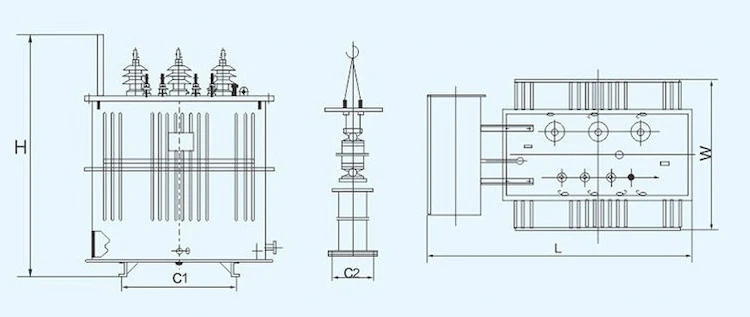
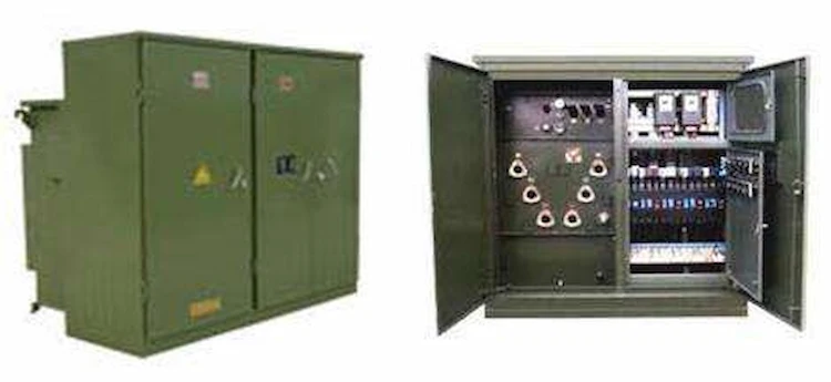
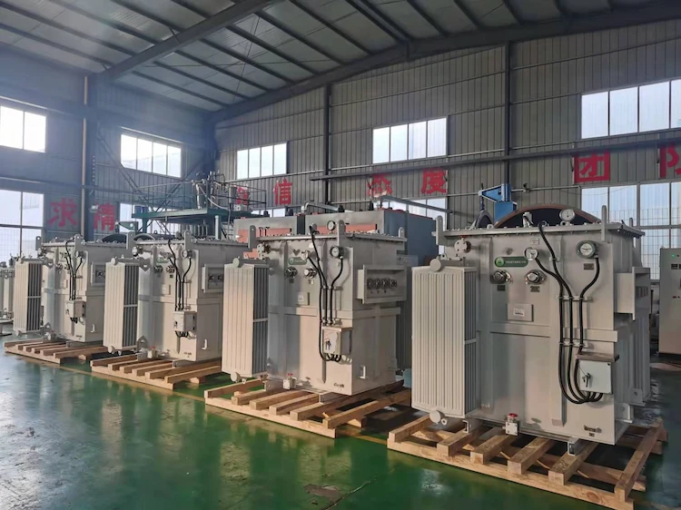
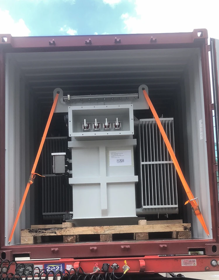
A hermetic liquid-immersed transformer looks very different compared to dry-type transformers, but they do have similar components.
On the top part of the transformer, you will be able to see low voltage bushings, which can consist of 4 or more.
The reason behind why the low voltage bushings are located on the top of the transformer is because the connections are quite enormous.
The reason why the connections are large is that the voltage is low while the current is high. This is what indicates that the low bushings are on the top of the transformer.
On the other side of the transformer are the high voltage bushings, which usually consist of three.
The indicator for high voltage bushings is simply the increase of voltage, and the current being reduced.
You also be able to see the current-carrying pieces of the high voltage bushings are small metal components that are expected to be thinner since the current carry will be significantly lesser.
In return for this, the voltage is going to be much higher, this is the reason why there is more insulation compared to the low voltage bushings.
Stepping up the voltage will require more insulation and increasing the current will require conductors that are thicker as well.
Breaking the hermetic-type transformer, you will be able to see the transformer core with three limbs, which is considered a three-phase transformer.
Furthermore, you will be able to see the yokes of the transformers which are located on the top and bottom part of the transformer. Lastly, the bushings that are sitting on top of the transformer.
Basically, hermetic-type transformers can be considered as dry-type transformers but with a box and with liquid as its cooling medium, in which the whole box is full with it.
The reason why this transformer is called a hermetic-type transformer is that they are completely isolated from the atmosphere or from the outside environment.
Basically, it is a hermit that has its parts completely covered inside to avoid contact with outside elements.
Once the transformer is totally assembled and sealed, it should never be opened ever again. But there can be exceptions to this such as when you want to do an oil analysis to it.
At the top of the transformer, near the bushings, you will be able to see a filling pipe, which is where you pour the oil in.
The lifting bolts also come with lifting eyes that are for both positioning the transformer or for securely installing it.
The temperature indicator basically tells you in real-time the temperature of the insulating liquid, which is the transformer oil that you are using.
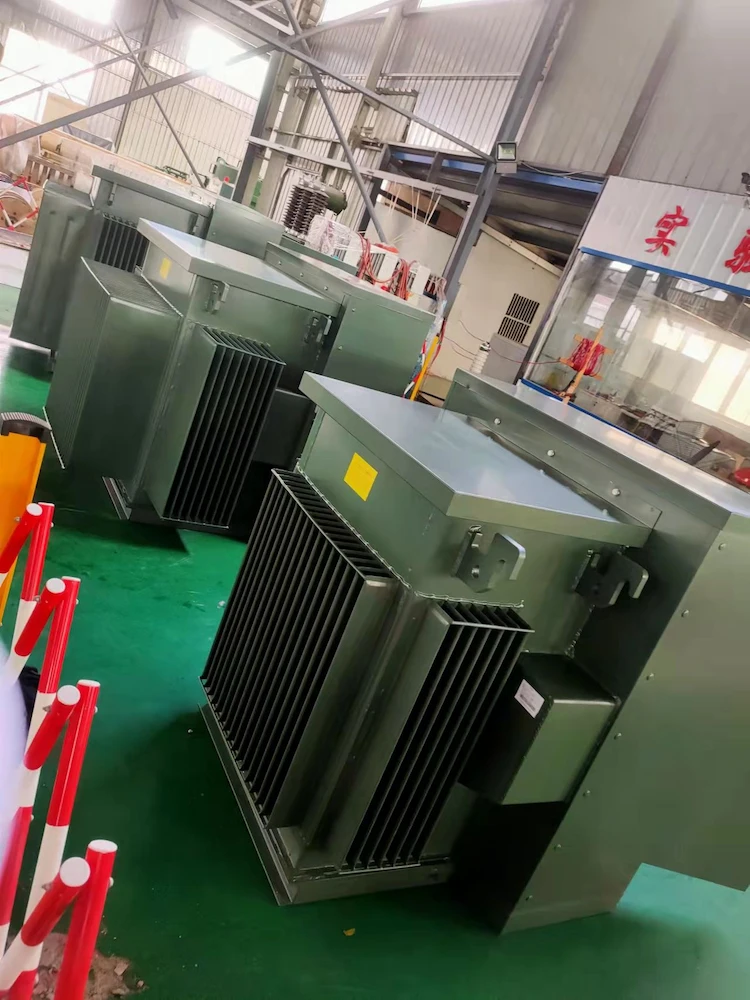
The casing of the transformer itself is not a perfect square, because they have these grills or fins attached to the sides, which are there for cooling purposes.
The way this processes is by absorbing the heat that is being generated by the transformer, and it will then pass it to the fins and the fins will be responsible for passing the heat on to the air.
In other words, it increases the contact surface area between the tank and the air, this means that you are going to get more heat transfer rate.
This keeps that transformer at regulated temperatures which are good for its overall health and operation.
In addition to that, you can load it more heavily up to a certain point such as by converting 5000 kVA to amps to a significant level.
This will greatly extend the transformer’s longevity especially if you do regular maintenance on it.
To begin with, you should review in detail the basics of the following electrical engineering principles first.
For starters, when a current is passing through a conductor, it is expected that it will create a magnetic field around that specific conductor.
If the current is passing to only a single direction, then this is called a “direct current”.
When a current is passing through a single direction, the direction of the magnetic field that is created in that conductor will remain in one direction.
In other words, the strength or place of the magnetic field is fixed simply because the current flow is in the same situation as well.
Moreover, the amount of current that is passing through the conductor will determine the exact strength of the magnetic field.
To achieve a constant current flow, this will require a voltage that is equivalent or constant as well.
This goes to say that the voltage potential of the conductor must be stagnant the whole time.
If you decide to use alternating current or better known as A.C, then you can expect the voltage potential to shift in the long run.
This basically means that the current flow will be dependable.
If the current flow is constantly changing, this will have to mean that the strength of the magnetic field will change as well. In simpler terms, this can be negative or positive depending on the operation or flow.
The peak of both the negative and positive will be considered as the indicators (if you use a graph), wherein the magnetic field is its strongest point as well.
When you change the voltage from positive to negative, the direction of the current flow will then reverse.
This is because once the direction of the current flow will reverse, the magnetic field’s direction will also be affected in which it will also reverse as well.
So, utilizing an alternating current, allows the current to move in two directions. In the case of the magnetic field, it will rotate in two directions as well.
But when it comes to the strength of the magnetic field, it will vary depending on the operation.
A current that is passing through a certain conductor will generate a magnetic field around that particular conductor.
Now, that you understood that electrical engineering principle, it is time to move on with the other one so that you can easily understand how 4500 kVA Transformers and residential pad-mounted transformers work.
For instance, take a magnet as an example, which has a south pole and a north pole.
Say for example that you place the magnet inside a coil.
The coil will be considered as a conductor, which has been wrapped around several times (to form the shape of the coil) with a light bulb connected at the top end of the coil.
The wraps are generally known as “turns”, but some engineers also call them loops. Regardless, you get the idea.
Basically, during this stage, there is nothing happening. While the magnet is resting at the center of the coil, there are currents in the coil but are not moving yet.
But when you move the magnet, it is expected that the light bulb will start to flicker, and by moving the magnet from left to right.
The reason why the light bulb will flicker is that there is a voltage being induced in the conductor.
Since the electrical circuit is closed, it is expected that there will be a current flow.
Either you move it to the left or right, the light bulb will flicker.
However, if you adjust the speed of how you move the magnet, the quicker you move it, the brighter the light bulb will shine.
On the other hand, if you were to move it slowly, the light bulb will not shine that much.
The reason behind this is the magnetic field.
As the magnetic field passes through the conductor, it will generate a voltage.
In the case that the magnetic field is being passed through the conductor at a fast rate, this will result in inducing a lot of voltage.
On the other hand, if it passes through at a slow pace, then it will only induce a weak voltage.
In short, the more voltage that you induce, the more current flow there will be.
On the opposite end, the voltage induced will result in less current flow.
Another way to vary the amount of voltage that is induced in the conductor is to leave the conductor vulnerable to the magnetic field that is fluctuating.
Reducing the number of turns in the coil will no longer make the lightbulb shine that much anymore simply because there is less voltage that is being induced.
If you move the magnet slowly, you will notice that the lightbulb will barely have any light anymore.
The more loops there are, the brighter the lightbulb will be.
This goes to show that it is simply not about how a magnetic field is able to pass through a conductor that determines how much is being induced but also the amount of conductor that is among the magnetic field.
As you have observed in the magnet example, when the magnet is stagnant or stationary, there is no voltage being induced in the conductor.
This means that the current that is flowing through the conductor will create a magnetic field that will surround that particular conductor.
By placing a conductor that is within a varying magnetic field, will induce the voltage that is in that particular conductor.
If you use the original conductor, simply wrap it into a shape of a coil which is by twirling it. Afterward, apply direct current.
This will result in creating a magnetic field that is around that coil.
This focused magnetic field is expected to have both a north and south that is producing an electromagnet.
You will be able to notice that in the graphs, the time will be fixed because the current flow is just constant.
As mentioned before, whatever the movement of the current flow is, it will also be the same for the magnetic field’s strength which means that both are at a constant level. Including the direction of the magnetic field as well.
When you use an alternating current to the coil, this will result in the magnetic field fluctuating, which means that it will increase and decrease as well.
The same goes for the situation of the voltage as well.
There are even times that the voltage will be positive, and it can be negative.
When it comes to changing the status of the charge from positive to negative or vice versa, this will cause the direction of the flow to reverse.
To sum it up, an application of a directing current to the magnetic field will create a varying magnetic field that is around the coil.
So, how will that relate to 4500 kVA Transformers and residential pad-mounted transformers?
Let the situation be like this, applying direct current to the conductor coil with the other coil not having any is called the secondary coil.
The first conductor that is in a magnetic field is called the primary conductor that is connected to a primary circuit that has current flowing through the conductor.
The secondary coil will have no voltage as of that moment, which means that there will be none induced in that coil.
This means that there will be no current flow in the secondary coil which is relevant because the magnetic field’s strength must be constantly shifting.
This process must be efficient because there will no induction of voltage in the secondary coil.
If you are going to apply an A.C current to the primary coil, this will generate a magnetic field to surround that particular coil.
In which the strength will fluctuate, either it will increase or decrease.
Since the secondary coil is being placed in that particular magnetic field, it is expected that the voltage will be induced in the secondary coil.
Connecting the secondary coil to an electrical circuit will allow the current to begin the flow.
You will also see that the voltage will be induced in the secondary coil in which it is equivalent to the original or primary voltage that is supplied in the primary coil.
This also means that there will be losses, but try to consider that the amount of voltage that is induced in the secondary coil will be replicated by the primary coil.
This results in an electrical transformer.
Applicable to 4500 kVA Transformer, residential pad-mounted transformer, and all the other kinds of transformers as well.
One of the main functions of a 4500 kVA Transformer is to basically increase or decrease voltage.
Whenever a transformer is being used this way, the principle above does not imply. This means there must be a change or adjustment.
In the magnet example above, if you move the magnet faster through the conductors, it will make the lightbulb shine brighter.
However, in this setup, that is simply not an option, because if you change anything in the primary coil, keeping in mind the current flow and magnetic field strength, will be moved on to the secondary coil.
The main goal here is to increase or decrease the voltage that is being utilized in the primary coil.
The best way to do this is by adjusting the number of conductors that are being used to support the magnetic field that is constantly changing.
Earlier, you learned that by adding more loops to the coil, you can make the lightbulb brighter or dimmer.
Once again, the reason why this event happens is that the amount of voltage that is being induced in that coil will be fluctuate depending on how many conductors are being utilized.
This goes to say that if you add more turns or loops, this will induce more voltage in that secondary winding.
This means that you are going to get more voltage than the primary winding contains.
Based on the graphs, the coil with a voltage that has been indicated in the long run and the coil with the second one goes the same, the amount of voltage that is being induced in the secondary coil on the right side of the screen is considered definitely more compared to a primary coil.
When it comes to cryptocurrency mining, you can definitely not go wrong with 4500 kVA Transformers since this type of transformer has a power rating that is more than enough to provide power to a single cryptocurrency farm with hundreds of graphics cards.
Cryptocurrency mining is definitely a good investment for people that prefer to invest in low-risk investments since you are not just turning your money into cryptocurrency directly.
However, if you prefer cryptocurrency mining over direct crypto investing, this will require a particular amount of budget since the prices of graphics cards have been skyrocketing and the same goes for 4500 kVA Transformers as well.
To get the best value out of your money, which means that your mining rigs will also be provided with safe and secure power, do not hesitate to contact DAELIM for professional advice with regards to cryptocurrency mining and electrical transformers.
If you are looking for a transformer that is capable of supporting a large crypto farm, then the 5000 kVA Transformer is definitely worth considering.
For small to medium crypto farms or mining rigs, you can save more money on transformers with a less power rating.
You can expect a return of investment in a year or so, but this would also depend on which crypto you are currently mining because as you know, cryptocurrency is very volatile.
DAELIM strongly suggests that you go for cryptos with good utility and are sure to stay in the market forever such as bitcoin, ethereum, and many more.
For the best advice, do not hesitate to contact DAELIM’s team of professionals for immediate assistance.
2022 Ultimate Pad Mounted Transformer Guide
-FIND THE BEST PAD-MOUNTED TRANSFORMER GUIDE ON THE WEB ALL IN ONE PLACE. SEE OUR LIST OF 14+FAQ RIGHT HERE.
How Do I Choose a Main Power Transformer? The Most Complete Guide
-This article focuses on the main power transformer, including how to select it? How to accept and transport? How to maintain?
High Voltage Distribution Transformer
-A lot of electrical companies use high voltage Distribution transformer to effectively operate at applications that are at high voltage levels.
After filling in the contact information, you can download the PDF.