Selection of 500kV Main Transformer in Hydropower Station
The construction of tens of millions of hydropower stations places high requirements on the technical indicators, parameters, manufacturing, transportation, and installation of the main transformer of the power station. Therefore, the type selection of the main transformer is very important. Four transformer types are introduced, including three-phase integrated transformer, single-phase transformer group, combined three-phase transformer, and field assembled three-phase transformer, and several aspects are introduced from transportation conditions, design difficulty, economy, failure risk and ease of maintenance. Analyze and compare aspects.
Main Transformer: The Ultimate FAQ Guide
Main transformer type introduction
At present, there are mainly four types of external ultra-high voltage and large-capacity main transformers: three-phase integrated transformers, single-phase transformer groups, combined three-phase transformers and on-site assembled three-phase transformers.
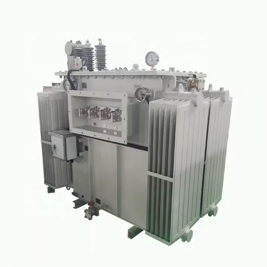
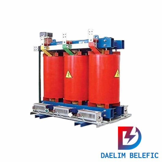
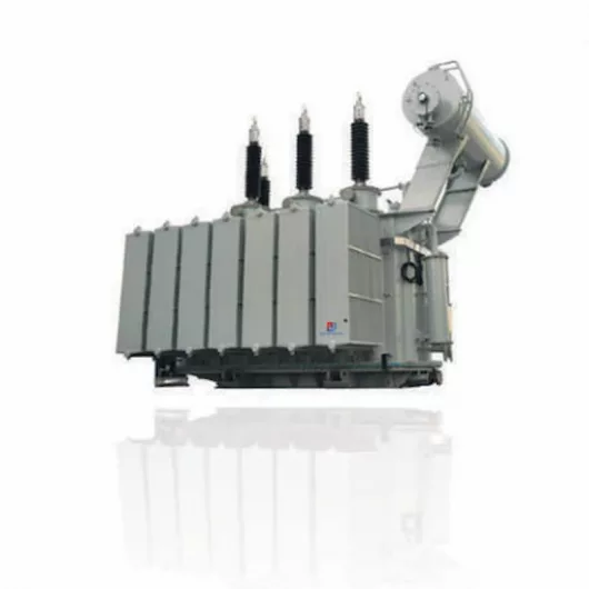
Three-phase transformers
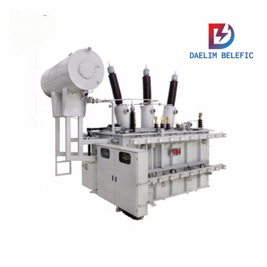
Three-phase transformers share one fuel tank for three phases and form a Δ connection inside the busbar box. The low-voltage side is led out by three bushings and connected to the IPB, and the oil circuit and the circuit are connected.
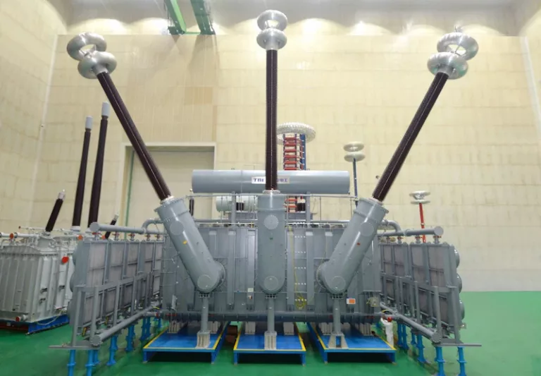
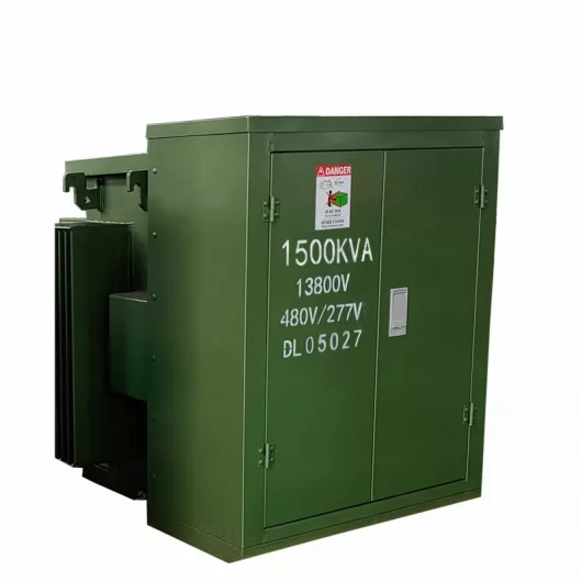
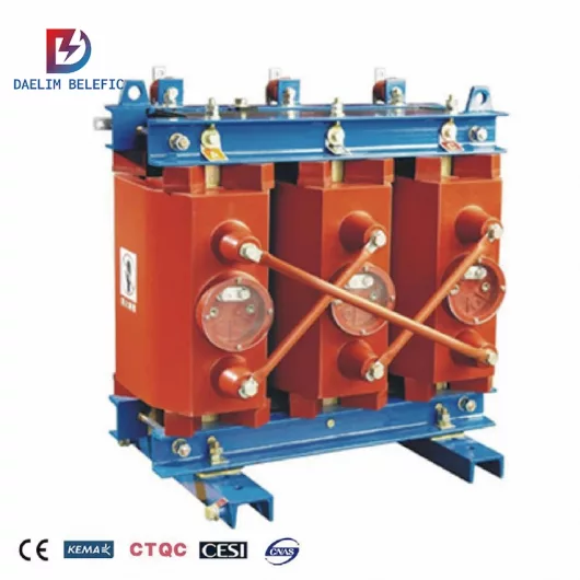
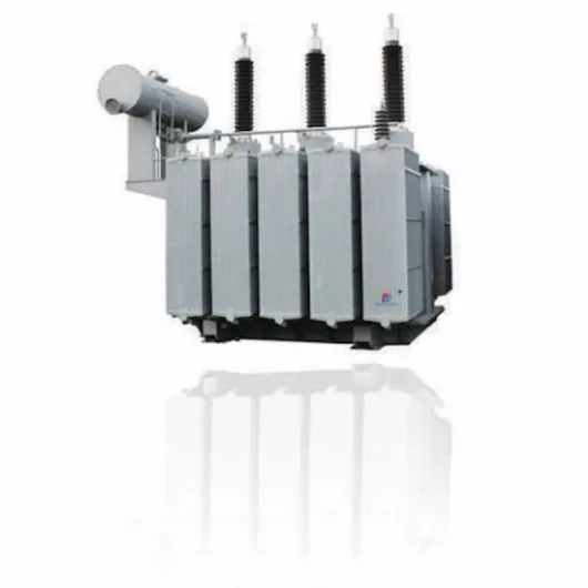
The single-phase transformer group is composed of three ordinary single-phase transformers connected to the outside Δ through IPB to form a three-phase transformer, and the oil circuit and the circuit are completely separated.
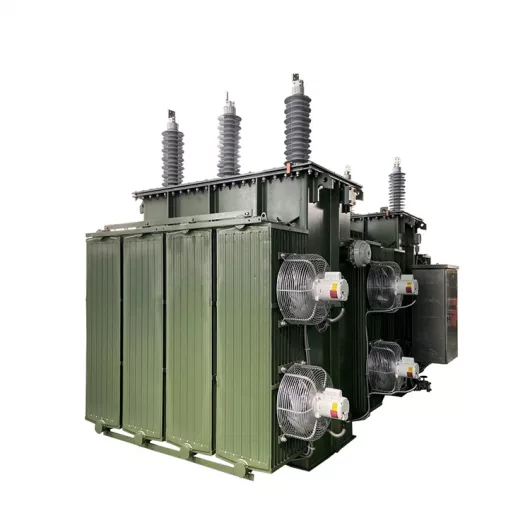
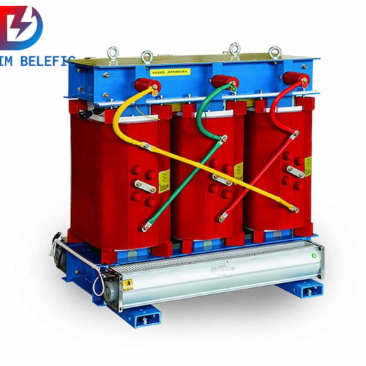
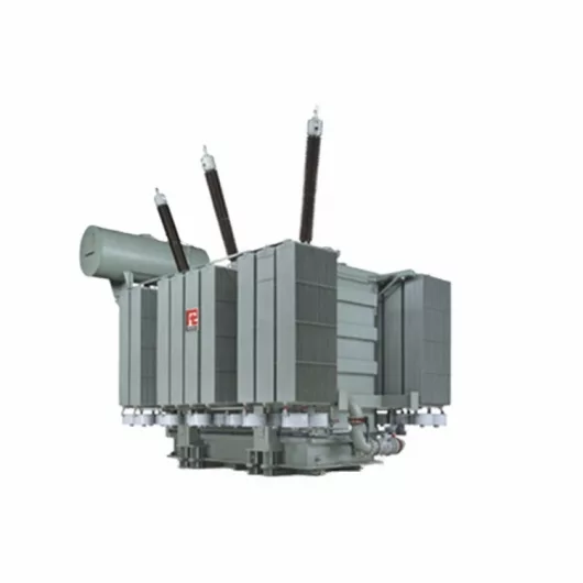
The combined three-phase transformer has a separate oil tank for each phase, the three phases are arranged together, the three-phase low-voltage side shares a busbar box, and the low-voltage side busbar delta connection is completed in the busbar box. The busbar box is installed after the three-phase body is in place, and the oil circuit and circuit are communicated through the busbar box.
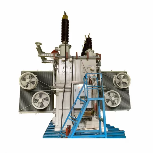
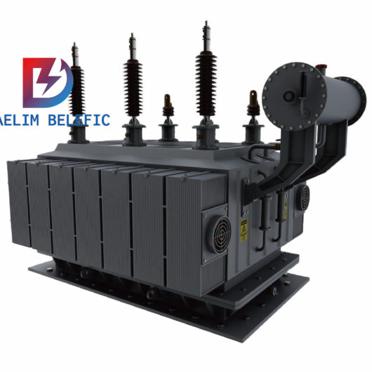
On-site assembly of three-phase transformers is also called disassembly and transportation transformers. The internal structure of the transformer can be made into several detachable parts according to the transportation conditions. The components are transported separately during transportation and then assembled into a whole on site. After assembly, the appearance and internal structure are the same as those of the three-phase. The integrated transformer is the same.
The transportation method of the main transformer mainly depends on its transportation weight and transportation size. Three transportation methods can be adopted: railway, highway and waterway.
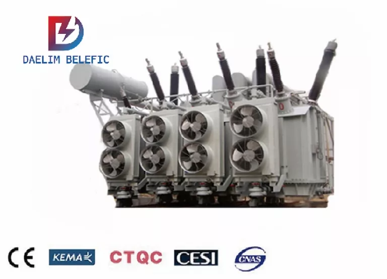
The three-phase integrated transformer occupies a small area, is convenient to install, use and maintain, and has a small investment. It has certain advantages and experience in design, manufacturing, and operation management. However, considering the product parameters of various manufacturers, the transport weight and transport dimensions of the three-phase transformer are all over the limit.
The transportation and installation of the single-phase transformer unit are relatively simple, the single-phase weight is light, the requirements for transportation conditions are loose, and the scope of the fault is small, but the three-phases are arranged separately, and a firewall is required between the single-phases, which occupies a large area.
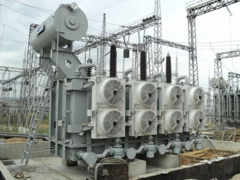
The combined three-phase transformer occupies a relatively small area, has a short installation time, is transported separately in phases, and has loose requirements for transport conditions. The site-assembled three-phase transformer occupies a small area and is not limited by the transportation weight. However, the transportation size of the fuel tank is large, and the on-site assembly and test site, equipment and environmental conditions are high, the process is complicated, the installation time is long, the technical risk is high, and the hydropower station The site is tight and does not have the conditions for the construction of a pre-assembly site and laboratory.
The main transformer should be the three-phase type first. If the transportation conditions and the layout site are restricted, a three-phase combined transformer should be used; if the transportation conditions are restricted but the layout site is not restricted, a single-phase transformer group can be selected.
Main Transformer Design and manufacture difficulty
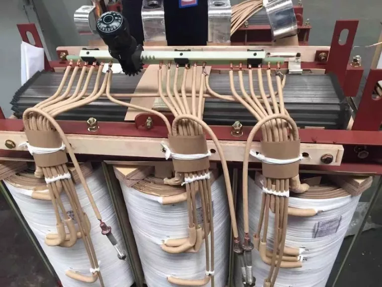
Both single-phase transformer banks and combined three-phase transformers are relatively mature structural types, with rich experience in design, manufacturing and operation.
The combined three-phase transformer needs to combine the three single-phase transformers by connecting the peripheral pipelines and the low-voltage bus box on site. The Δ on the low-voltage side is connected in the low-voltage bus box. At the same time, the neutral point of the high-voltage side winding is in the low-voltage bus box. It is formed in the middle and led out of the box through the bushing, which makes the design and manufacture of the combined three-phase transformer far more difficult than the single-phase transformer group.
The manufacturer needs to carry out special design for the electromagnetic shielding of the low-voltage bus box of the combined three-phase transformer and the components around the internal lead. At the same time, the oil circulation cooling of the low-voltage bus box, the three-phase connection structure, the three-phase shared base, and the installation of the transformer should also be considered. And size control and other issues.
The economic factors of the transformer mainly consider the comprehensive cost of the transformer itself, such as the price of the transformer, transportation costs, and equipment investment.
In terms of equipment prices, according to the data provided by various manufacturers, it can be seen that for the same transformer manufacturer, the price of a single-phase transformer group with the same capacity is slightly higher or equal to that of a combined three-phase transformer, the price difference is not big, and the transportation cost is basically the same.
In terms of equipment investment, it is mainly considered from two aspects: the setting of the standby transformer and the increase of the length of the IPB bus. Regarding the setting of standby transformers, taking into account the uncertain factors in the transportation of standby transformers between the left and right of the hydropower station, combined with the local standby transformer setting method of the hydropower station, it is clear that the left and right banks of the power station are equipped with standby transformers. The low-voltage side of the single-phase transformer group is connected to the IPB, and each single-phase transformer group adds about 50 single-phase meters of the IPB bus.
From the above economic comparison, the investment of the combined three-phase transformer is significantly higher than that of the single-phase transformer group.
The three single-phase units of the single-phase transformer group are completely isolated and the oil circuits are separated. The probability of a two-phase or three-phase short circuit on the low-voltage side of the transformer is very small, and the failure of any phase will not affect the other two phases; and the combined three The low-voltage and neutral-point leads of the phase transformer are both arranged in the low-voltage terminal box. There is the possibility of two-phase or three-phase short circuit at the phase connection, and the fault may be transmitted to the other two phases through the oil circuit, so the combined three-phase transformer fails And the risk of failure to expand is greater.
When a single-phase transformer group fails, it is easy to replace it. You only need to remove the high and low voltage side connections to exit the faulty phase, put the spare phase in place, and connect the high and low voltage sides for corresponding tests.
After the combined three-phase transformer removes the connection of the high and low voltage sides, some transformer oil needs to be discharged, the low voltage bus box is removed, the common oil system pipeline is removed, and the faulty phase is removed.
Install the spare phase in place, connect the common oil pipeline, install the low-voltage bus box, and then carry out the corresponding test. The replacement of the standby transformer of the combined three-phase transformer is more cumbersome and takes longer than the single-phase transformer bank.
Large-scale transformers in hydropower stations generally use forced oil circulation air cooling and water cooling. The air cooling method is simple to operate and maintain, but it is noisy and has certain requirements for ventilation and heat dissipation. The water cooling method has high efficiency and low noise.
The main transformer of the hydropower station is arranged in the underground cavern with limited ventilation and heat dissipation conditions. The hydropower station plans to adopt a forced oil circulating water cooling method, each single phase is equipped with a set of coolers, and the automatic sand discharge function and the number of coolers are fully considered].
The feasibility of adopting single-phase transformer bank in hydropower station is comprehensively analyzed and studied from the aspects of transportation conditions, design difficulty, economy, failure risk and ease of maintenance.
At the same time, under the premise of satisfying transportation, comprehensive calculation and evaluation of transportation cost, equipment cost and power transformation cost must be carried out to choose a more economical and efficient transformer structure.
Lorem ipsum dolor sit amet, consectetur adipiscing elit. Ut elit tellus, luctus nec ullamcorper mattis, pulvinar dapibus leo.
Custom Main Transformer
When you need to find more than just existing transformers, Daelim’s Transformer Service Center can help you design and produce distribution transformers that meet your unique needs.
We have our own factory and a professional team of engineers, which can design and modify application requirements that meet all your conditions.