10 kv Oil Filled Transformer
Fault Diagnosis and Analysis of 10 kv Oil Filled Transformer 10 kv Oil filled transformer
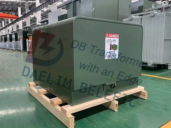
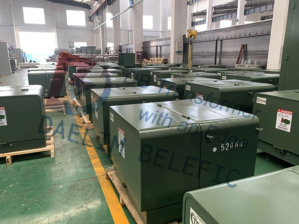
An electricity transformer box, also known as a transformer enclosure or distribution box, is a protective casing used to house electrical transformers in power distribution systems. These boxes are designed to safeguard transformers from environmental factors such as weather, vandalism, and unauthorized access, while also ensuring the safety of people and animals in the vicinity.
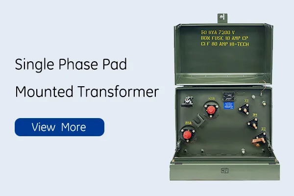
This article explains in detail the principle of residential electricity transformer box, how to layout, how to protect against lightning, how to reduce noise and everything else about Single phase pad mounted transformer.
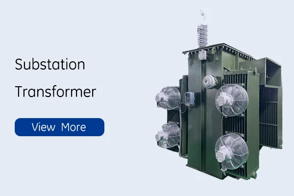
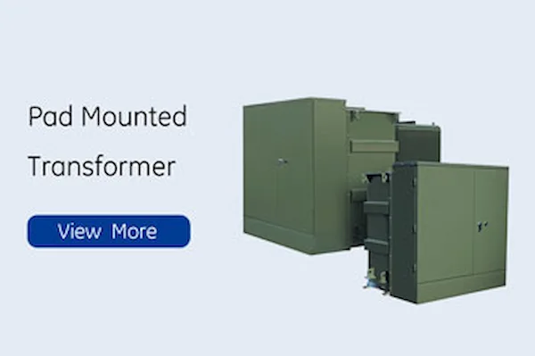
Choosing Daelim’s pad mounted transformer as your electricity transformer box supplier offers multiple advantages that make them an ideal choice for various applications and industries:
1.Quality Assurance: Daelim adheres to multiple international standards such as IEEE C57.12.34, IEEE C57.12.28, CSA C227.3 & CSA C227.4, ensuring high-quality performance and compatibility with global markets. This guarantees a reliable and efficient product for your electricity transformer box.
Safety Features: Daelim’s pad mounted transformers prioritize safety with sealed high-voltage and low-voltage compartments that minimize accidents. The lockable cabinets prevent unauthorized access, making them well-suited for locations where safety is crucial.
Versatility: Daelim’s pad mounted transformers come in radial and loop feed configurations, providing compatibility with different types of circuits and offering seamless integration into existing infrastructure.
Energy Efficiency: Optimized for maximum efficiency, Daelim’s transformers utilize aluminum or copper windings based on specific project needs. This design ensures low energy losses and cost savings over the transformer’s operational life.
Compact Design: The space-efficient design of Daelim’s transformers allows for easier installation in areas with limited space or where aesthetics are important.
Reliability: Known for producing reliable and durable transformers, Daelim ensures long-lasting performance and reduced maintenance costs for your electricity transformer box supplier.
Customization: Daelim can customize their transformers to meet specific customer requirements, making them a flexible choice for various applications, including electricity transformer box suppliers.
By choosing Daelim’s pad mounted transformer for your electricity transformer box supplier, you can provide your customers with a safe, reliable, and efficient power distribution solution, addressing transformer shortages while offering a high-quality, compliant product.
Electricity transformer boxes play a crucial role in power distribution systems, providing a safe and secure environment for housing transformers. They are designed to withstand various environmental factors and protect the transformers from damage, ensuring reliable and continuous power supply to end users.
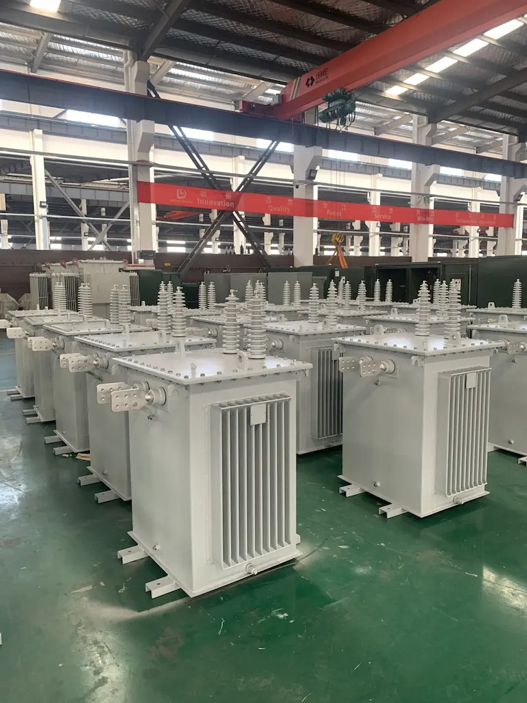
Materials and Construction: Transformer boxes are typically constructed using robust materials like galvanized steel, stainless steel, or fiberglass-reinforced polyester (FRP), which offer excellent resistance to corrosion, impact, and weather-related damage. The choice of material depends on the specific application, local climate, and other environmental factors.
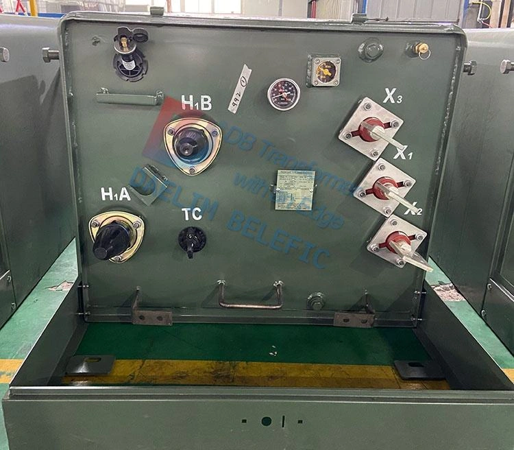
Design and Features: Transformer boxes come in various designs and sizes to accommodate different types and capacities of transformers. They often feature hinged or removable doors for easy access, allowing maintenance personnel to inspect, service, and repair the transformer when necessary. Ventilation grilles or louvers may be included to dissipate heat generated by the transformer, preventing overheating and ensuring optimal performance. Locks and safety signage help prevent unauthorized access and ensure the safety of the public and animals.
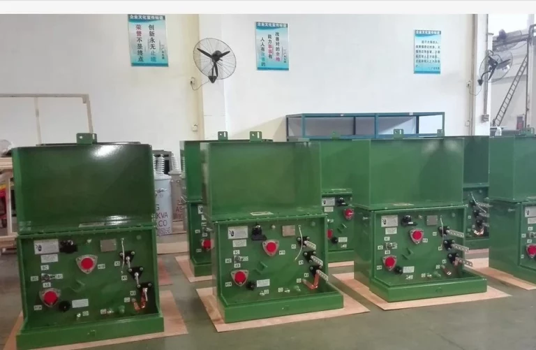
Installation: Electricity transformer boxes can be installed in various locations, depending on the requirements of the power distribution system. For pad-mounted transformers used in underground distribution systems, the boxes are placed on the ground, often on a concrete pad. In overhead distribution systems, transformer boxes can be mounted on utility poles. In both cases, the boxes should be installed in accessible locations to facilitate maintenance and repairs.
In conclusion, electricity transformer boxes are vital components in power distribution systems, providing a protective environment for transformers and ensuring the safety of people and animals in the vicinity. By selecting the appropriate material, design, and installation method, electricity transformer boxes can ensure the long-lasting performance and reliability of transformers in various applications.
The influence of ambient temperature on electricity transformer box is mainly reflected in the insulation. electricity transformer box insulation medium mainly relies on electricity transformer box oil, insulating cardboard and cable paper, etc. electricity transformer box oil as a medium for cooling and insulation, long-term heat at high temperatures will accelerate the oxidation and cracking, the generation of stable oxides and organic acids, resulting in electricity transformer box oil acid price increases, viscosity increases, and even precipitation of sludge and water, affecting its insulation and heat dissipation level, but also generate flammable gas, causing The gas relay will send letters and action. Insulation materials such as insulating cardboard and cable paper will lose their elasticity, become brittle and lose their mechanical strength, thus losing their electrical strength in the long term under heat.
For this reason, the electricity transformer box operates at an ambient temperature of up to +40°C, the hottest monthly average temperature of +30°C and the highest annual average temperature of +20°C.
Ambient humidity has little effect on the daily operation of the electric transformer box, because the electric transformer box body is generally sealed tightly and has good water resistance, so that the moisture in the air does not affect its interior during operation. However, when the electric transformer box is out of service or maintenance, the impact of environmental humidity on the electric transformer box should not be ignored.
(1) electricity transformer box maintenance, according to the provisions, the electricity transformer box body allowed to be exposed to the air time according to the relative humidity of the air at the time, less than or equal to 65% for 16 hours, less than or equal to 75% for 12 hours, otherwise it will lead to the body insulation level of otherwise it will lead to the insulation level of the body.
(2)When the electricity transformer box is out of service, if it is out of service for a longer period of time, it will be eroded by moisture and salt spray, resulting in the core to ground insulation dropping, or even to zero. The winding is less affected because its exterior is dipped in insulating paint, so it is not easily affected by moisture. It is difficult to dry the core after it is damp, this is because the core has a certain thickness, baking is only more effective for the drying of the surface, its internal moisture is difficult to force out, so it needs special protection against moisture in the core.
Single phase pole transformer adopts rolled iron core technology, which can greatly reduce the no-load loss and load loss, and has simple structure, small volume, light weight, low noise, convenient and flexible installation, which is more suitable for the “small capacity, dense distribution” power supply mode, so that the power supply radius of low-voltage lines is greatly shortened. The manufacturing quality of single phase pole transformer is becoming more and more stable and improved, and it has outstanding advantages in economy and technicality.
However, for all kinds of residential communities in cities and towns, all kinds of demolition and resettlement areas and some other customers with high requirements for landscape in cities, single phase pole transformer still has the following limitations in residential areas.
1 ) The single phase transformer on the pole and the overhead 10 kV distribution line installed in the residential area are a potential safety hazard for the residents.
2) Increased floor space and impact on parking, landscaping and other activities in the residential area.
3) The single phase pole transformer and its supporting overhead lines are more likely to be stolen or vandalized because they are exposed without additional protection measures.
4)single phase pole transformer is not conducive to environmental beautification.
The single phase pad mounted transformer has almost all the advantages of the single phase pole transformer and provides a possible solution to the limitations of the single phase pole transformer application. It has been welcomed by power supply companies, local governments, real estate developers, property management departments and residents.
Single-phase pad mounted transformer is also called high-voltage/low-voltage single-phase pre-assembled substation. It consists of single-phase transformer, high-voltage room and low-voltage room, and the three are arranged in a zigzag pattern, closely cooperating with each other. Generally, two-phase line voltage is used for high voltage, and single-phase three-wire structure is used for low voltage side, so that the low voltage load is equally distributed to two phases and the current through zero line is zero when the load is balanced. The transformer core adopts rolled iron core without joints structure, which has small no-load loss and low noise. The high-voltage chamber is equipped with insulating sleeves for connecting elbow-type cable plugs with load breaking capability.
The elbow cable plug can be plugged and unplugged under full load of the transformer, and the bushing is connected to the elbow cable plug to seal the charged part inside the insulator, forming a fully insulated structure, and the surface of the high-voltage end is not charged to reliably ensure personal safety.
Adopting backup fuse (ELSP type) and plug-in fuse (Bay-0-net type) in series protection, the protection principle is advanced, economical and reliable, and easy to operate.
ELSP type is oil-immersed current-limiting fuse, installed inside the box, in case of a fault inside the box, for the protection of high-voltage lines;
Bay-0-net type is oil-immersed inserted type double sensitive fuse fuse, when the transformer low voltage side of the short circuit fault, overload and oil temperature is too high fuse, can be easily replaced in the field fuse, low voltage room can be installed plastic case switch and power metering device.
In addition to the main advantages of single phase pole transformer such as energy saving, single-phase pad mounted transformer also has the following features.
1 ) Beautiful appearance, compact structure. Model D12-M-R-80/10 single-phase pad mounted transformer power station, its length, width and height are 0.68, 0.755, 1 .285 m, respectively, model ZGD11-H-80/10 single-phase pad mounted transformer length, width and height of 1 .23, 1 .11 and 1 .17 m respectively;
The single-phase pad mounted transformer can be placed at the entrance of residential units or in the green belt if the appearance of the single-phase pad mounted transformer is further decorated according to the overall architectural and greening style of the district;
If the noise and vibration standards and meet other fire protection requirements, because it occupies very little space, can also be placed in buildings, such as the ground floor bicycle storage, stairs below, etc., only need to consider good fire, safety isolation and warning measures, which not only reduces the area, the overall environment of the residential area is also a significant role in the beautification.
2 ) Advanced and reliable performance. single-phase pad mounted transformer adopts the international advanced R-type rolled iron core technology, even under full load, the noise is extremely low (less than 45 dB); fully sealed, fully insulated structure, the use of high ignition point oil (R-TEMP oil, ignition point up to 312 ℃), no fire hazards, the use of absolute safety; Single phase pad mounted transformer has strong overload capacity, allowing overload 2 times, 2 h, overload 1 .6 times, 7 h without affecting the life.
3 ) Reasonable and perfect function, flexible wiring, easy to repair or replace. According to the power supply requirements of different communities, it can be used for both ring network and terminal, which is convenient for conversion and greatly improves the reliability of power supply, and the single-phase pad mounted transformer has a small fault impact; single-phase pad mounted transformer does not need to work on the pole or on the pedestal when it fails to repair or replace, and its weight is much lighter than that of three-phase box-type transformer, and it does not need large construction machinery. The weight is much lighter than that of a three-phase box-type transformer, and no large construction equipment is required, so it is easier and faster to repair or replace, which can significantly shorten the repair time.
There are several single-phase pad mounted transformer power supply methods available according to the requirements of different residential areas in terms of load nature and reliability of power supply and other needs of customers.
1 ) The power supply method of distribution substation or outdoor ring network cabinet, high-voltage cable branch box and ring network type single-phase pad mounted transformer forms a chain power supply method. The advantage of this power supply method is that each single-phase pad mounted transformer has two power sources and high reliability of power supply;
However, the disadvantage is that the length of high-voltage cable is long, the investment is slightly high, the operation mode is slightly complicated, and the interlocking problem between two power sources needs to be solved. This kind of single-phase pad mounted transformer is suitable for single-phase pad mounted transformer to supply power to customers with dual power supply requirements.
The high-voltage power supply line is single-phase type, through two single-core cable or double-core cable balanced connection in A, B phase, B, C phase, C, A phase, the box transformer using two T-type casing + elbow cable plug for ring supply connection, play the role of four-way, respectively, connected to the incoming line, ring line, outgoing line, lightning arrester position, and in the outgoing line position to install a two-position low-voltage load switch, used to connect or cut off the single-phase pad mounted transformer phase pad mounted transformer, or replace the two-position load switch with an elbow-type cable plug with double fuse protection, and plug and unplug directly with electricity.
2) The distribution office or ring network cabinet, high-voltage cable branch box and ring network type or terminal type single-phase pad mounted transformer with two-phase low-voltage load switch form a trunk type power supply method. The characteristics of this power supply method are that the single-phase power supply from the distribution office or ring-net cabinet to the high-voltage cable branch box, the incoming line is three-phase type, the outgoing line is single-phase type, through two single-core cable or two-core cable balanced connection in A, B phase, B, C phase, C, A phase, the outgoing line circuit is controlled within 6 channels, each channel does not exceed 3 single-phase pad mounted transformer The total number of single-phase pad mounted transformers in each branch box shall not exceed 18;
The first two single-phase pad mounted transformers in each outlet are ring type, and the last one is terminal type. The advantage of this method is that the three closest box transformers can be connected in series with the actual site distance, saving investment in high-voltage cables; the disadvantage is that there is only one power supply, and the reliability of power supply is lower than that of chain power supply.
3 ) Distribution substations, outdoor ring network cabinets and single-phase pad mounted transformers with double fuse protection (no load switch) form a radial power supply.
(no load switch) ring-grid type or terminal type single-phase pad mounted transformer to form a radial power supply method. This power supply method is characterized by one main and one standby power supply from the distribution substation to the outdoor ring-net cabinet, and then from the outdoor ring-net cabinet (not the high-voltage cable branch box) to the single-phase pad mounted transformer, and the cable at each outlet is extended to double cable terminals (2 A-phase, B-phase, C-phase, respectively) and divided into 3 single-phase outlets (A, B-phase, B, C-phase, B-phase, C-phase, B-phase, C-phase, B-phase, C-phase, C-phase). phase, B, C phase, C, A phase), the first two units of each line out for the ring type single-phase pad mounted transformer, the last one for the terminal type, no more than 3 units each way.
The advantage of this method is that it can be combined with the actual distance to the nearest three box transformers in series, saving investment in high-voltage cables;
At the same time, because the external ring network cabinet has a dual power supply, so it has the advantages of both the above-mentioned chain type and trunk type: the reliability of power supply is higher than the trunk type power supply, and the investment is less than the chain type power supply;
The disadvantage is that the power supply inside the ring network cabinet is one main and one standby, and there is a short power outage time.
The basic principle of electric transformer box (pad mounted transformer) reactive power compensation is that the closer to the end of the power supply, the better the economic results will be. The reason for this is that the closer to the end of the supply, the more technology is used at the compensation point to reduce the line losses caused by reactive currents.
In the current situation, the electricity transformer box (pad mounted transformer) is generally configured in a centralized compensation mode. The biggest advantage of this model is the maintenance, relatively low cost, and relatively simple construction. However, there are shortcomings, the disadvantage of this model is that its effect can only be produced on the upper equipment and the grid, so it does not play a significant role in the low voltage network of the utility transformer losses, and to make the reactive power compensation mode to reduce the losses in the grid, it is necessary to make the electricity transformer box (pad mounted transformer) reactive power compensation towards transformer) towards the client, which, of course, requires decentralized reactive power compensation.
In general, the configuration principles of pad mounted transformer reactive power compensation are:
1) Strengthen the mutual combination between decentralized compensation as well as centralized compensation.
2) To master the effective combination between balance and overall balance, of which the main object should be local.
3) Effective combination between voltage regulation and loss reduction, while paying attention to loss reduction as the main goal.
(4) Master the relationship between user compensation and compensation of the power sector.
In urban low-voltage distribution network, tracking compensation means that the reactive power compensation device is used as a protection device and the low-voltage capacitor bank compensation is controlled on the 0.4kv bus. This way can replace and random two compensation mode, and its compensation effect is better. This compensation mode has both advantages and disadvantages, the advantage is that its operation and maintenance workload is relatively small, in addition to the operation mode is relatively flexible, so it will be more reliable, and its life will be relatively long. However, the disadvantage of this compensation mode is that the initial investment is relatively large, and the protection and control devices are relatively complex for this compensation mode.
In the urban low-voltage distribution network, the specific meaning of the follower compensation method is that the low-voltage capacitor is connected to the electric transformer box through the low-voltage insurance to compensate the no-load reactive power of the transformer. The no-load reactive power of the transformer is a major part of the reactive power load of the relevant power unit, but for the light-load electricity transformer box, this part of the use of losses in the entire power supply occupies a large proportion, which will lead to rising losses. Of course, the follower compensation also has its advantages. The advantage of reactive power compensation in cities is that it is relatively simple to maintain, and its maintenance and management is also relatively easy, which can also improve the utilization efficiency of the electricity transformer box and reduce the loss of reactive power compensation, so in this regard, this reactive power compensation method has considerable economic benefits. And it can be considered as one of the most effective and practical means of reactive power compensation for electricity transformer box in cities today.
In the urban low-voltage distribution network, the random compensation method means that the motor is connected in parallel with the low-voltage capacitor bank, and the motor is switched on simultaneously through certain protection and control devices. Of course, the random compensation method in reactive power compensation is mainly to compensate the excitation reactive power and is used to reduce the reactive power consumption of the motor. Therefore, this type of compensation can better limit the problem of gratuitous power load of the relevant power-using units. At the same time, the significant advantage of random compensation in the city electricity transformer box reactive power compensation is that when the relevant power equipment is in operation, reactive power compensation will be put into, when the power equipment is out of operation, the corresponding compensation equipment will also be withdrawn, and will not need to adjust the compensation capacity relatively frequently. Therefore, it can be said that in this compensation method, the maintenance is simple. In addition, this mode is relatively small in terms of accident rate and relatively small in terms of investment.
Knowing the current stage of electricity load in high-rise residential areas, a part of electricity transformer box for house utility has a large loss due to its long-term connection to the grid system operation. At the same time, the power supply and distribution system is an important link in converting voltage and distributing electricity for residential communities. Therefore, the reasonable selection of electric transformer box for house utility is of great practical significance to improve the quality of electricity consumption of residential customers, and there are still some misunderstandings in the selection of electric transformer box for house utility capacity, such as determining electric transformer box for house utility only by calculating the electricity consumption load. In addition to the economic operation of the electric transformer box for house utility, it is also necessary to consider whether the residential area will be transformed or new electric equipment will be added in the future. Therefore, the design of electricity transformer box for house utility capacity should be left with a certain margin.
According to the above calculation of residential electricity load, public electricity load and electric vehicle charging load, the total electricity load of the planned community is: PT=Pa+Pb+Pd=395.01+281.4+369.6=1046.01kw
The capacity of electricity transformer box for house utility should not be too large, because the smaller capacity of electricity transformer box for house utility can shorten the radius of low-voltage power supply, and can also protect the safety of residential users to a certain extent. 2 electricity transformer box for house utility is placed in a distribution room, and its load ratio is 0.85, according to 800kVA planning, the number of electricity transformer box for house utility in residential area is Np= 1046.01÷0.85÷800=1.54
Therefore, the planning capacity of electric transformer box for house utility is 1600kVA. At the same time, for the development and transformation of the next 5 to 10 years as well as safety considerations, the planning of electric transformer box for house utility is reserved in part. margin, this paper chose to increase the 85%. That is, Np=1600÷0.85÷800=2.35 The planned residential district finally needs to set up a total of 3 electricity transformer boxes for house utility, with a total capacity of 2400kVA and two distribution rooms.
At the present stage, the residential community will generally combine the geographical location, climate situation, environment, power supply conditions of different areas as well as grid load characteristics, development scale and other factors to develop a comprehensive consideration to meet the different forms of power supply and distribution system to achieve the purpose of cost reduction and loss reduction. In this paper, the power supply method of the residential district is mainly set as a double-loop power supply method combining distribution room, substation room and cable.
In other words, according to the area, location and power supply conditions of the community, including the distance between residential buildings, the height of residential floors and load conditions, two power supply circuits are led from the power supply, and the connection of distribution stations and transformer box power line of substation room, so that the residential community forms a ring network power supply. The reasonable configuration of distribution room and substation room is realized.
In this paper, two power sources are planned for the residential area. As there are more power-using devices in the area, in order to avoid the situation that all power inlets lose power at the same time and cause important load blackout, the safety and reliability of power supply are ensured by setting up backup power sources in the residential area.
Therefore, a backup power supply is also considered in the residential area planned in this paper, in order to ensure normal power supply in the area during maintenance and repair of power-using equipment, and at the same time to ensure that the two power supplies cannot stop working at the same time, nor can they be used as a backup for each other. Generator sets, uninterruptible power supply, emergency power supply, etc. for backup power.
Some areas can temporarily not set up emergency backup power supply because there is no primary and secondary power load, such as rural old and new communities, staff dormitories, etc.; small-scale commercial residential areas, high-rise low-rise commercial residential areas and low-rise, multi-story residential areas, there is a secondary load, when there is no second power point access in the district distribution system, can also consider setting up a diesel generator set as the main, UPS, EPS as a supplement to the power supply emergency power.
The majority of the load composition in the high-rise district planned in this paper is three-stage load. It should be specially noted that although the domestic water pump, sewage equipment, fire-fighting equipment lighting, and distribution station lighting equipment belong to the third-tier load, it is stipulated that they should be distributed according to the second-tier load. In the distribution system, when the electricity transformer box for house utility or the supply transformer box power line has a temporary fault or a common fault, in order to ensure that the power supply is not interrupted or the fault can be recovered in time, it can be recovered by switching the power supply or adjusting the operation mode. The power supply for secondary loads contains the following two forms:
(1) Double-loop dual power supply mode. The first circuit is the direct power supply from the grid, while the second circuit is connected to the nearby grid or self-provided generator set.
(2) Dual-circuit power supply with two different buses. It is in the same substation.
And the tertiary load is carried out using the single circuit power supply method, in which the low-voltage distribution level can only be the form of power supply for one, two and three levels of loads co-existing, in which the third level is mostly dominant. The self-provided power supply is then set up in accordance with the demand for power supply for primary and secondary loads [60].
The following conditions should be satisfied in the planning and design of the residential area power supply and distribution system:
(1) If a 10 kV power supply and distribution system is set up in the district, the ring network interconnection should be adopted as far as possible for power supply.
(2) In high-rise residential areas, substations are generally set at 10/0.4 kV, including outdoor pre-installed substations and indoor substations, and indoor substations are generally planned on the first floor or negative floor of the building.
(3) The villa area and other low-rise and multi-story residential areas should be planned with pre-installed substations in regional blocks, also set at 10/0.4kV.
For further analysis of the power supply and distribution system of high-rise residential area, the design scheme of its power supply and distribution system should not only load the above-mentioned regulations but also consider the following situations:
(1) When the community planning project is larger, two 10kV lines can be considered to be separately led from different substations, containing one or several groups, and one or several ring network interconnection stations can be set up in the sub-region, and then distributed around through the center of the ring network to supply power in a radial manner.
(2) Cable and closed busbar should be selected for high and low voltage power supply.
Since the power factor value of household power equipment in residential communities is generally 0.8 to 0.85, it is impossible to reach 1.0. Therefore, in order to reduce losses, enhance power supply quality and improve power supply service, it is usually chosen to improve power factor or meet the regulations through some reactive power compensation methods, and the specific measures are as follows:
1) Select the capacity and number of electricity transformer box for house utility reasonably and appropriately
(2) reduce the inductive resistance in the lines of the supply and distribution system as much as possible, followed by attention when laying cable lines, and if necessary, use measures such as concentric structure;
(3)Full consideration should be given to the selection of motor capacity, and sometimes there may be a case of using synchronous motor. At the present stage of residential areas will generally choose to use the above measures to improve the user power factor, but when the results are not satisfactory or the improvement effect is not good, then will consider in the distribution system electricity transformer box for house utility low-voltage side bus in parallel with a number of capacitor banks for compensation, that is, to increase the reactive power compensation device, after compensation so that the power factor The reactive power compensation capacity should be calculated by 15%~30% of the capacity of electricity transformer box for house utility, and the capacity of the compensation capacitor bank can be determined according to the result. At the same time, there should be a corresponding margin for the installed capacity of compensation capacitor.
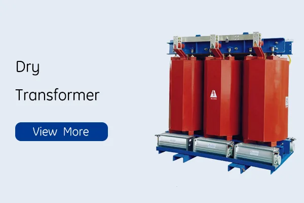
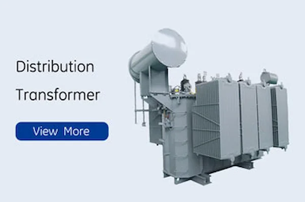
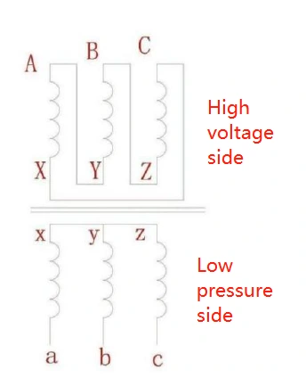
There are two types of transformers, namely dry-type and oil-immersed transformers. For high-rise residential areas, dry-type transformers are generally chosen because of their high short-circuit resistance and many advantages, such as good fire and explosion-proof performance, low noise pollution without a large installation area, and no need for extensive maintenance work. For the transformer connection using DYN11, this connection diagram and advantages are shown in Figure:
(1) Since the third harmonic excitation current is closed in the original winding, the total zero-sequence and third harmonic potential is close to zero, so the neutral low-voltage potential does not drift, so the quality of each output voltage is relatively high. At this stage, the third harmonic content in residential buildings is increasing, and this connection has good lightning protection characteristics, so it makes sense to set up DYN11 connections in residential communities.
(2) The zero-sequence impedance of the DYN11 connection is relatively small, which is better for eliminating single-phase short-circuit faults.
(3) DYN11 connection for access to single-phase unbalanced transformers are not subject to current limitations, so there is no restriction on access to the amount of load. Thus, the transformer is fully utilized.
Regarding the location of the distribution room, including high and low voltage distribution should be independent of the residential community and cannot be common with other equipment. The distribution room should not only consider electricity safety but also economic and technical conditions: it should be located in a convenient location for transportation, and can also be set close to the load center or at the high-capacity power equipment and the power supply side, which is convenient for high-voltage and low-voltage access lines;
It cannot be set directly above or below the residential rooms, and should be pulled away from them, and should not be located in the low-lying residential terrain, in order to prevent the occurrence of moisture and flooding, and should also have the function of drainage and water seepage prevention; for the time being, most of the new communities will be set on the first floor of the residential building, the first floor or on the same floor with the underground garage. And establish corresponding moisture-proof measures and ventilation facilities for power distribution equipment, such as adding moisture-proof base, fire-fighting equipment, fire-extinguishing equipment, etc. If environmental conditions allow, the location should be concealed and not less than 3m from the residential building.
The power distribution in the small area planned in this paper is taken care of by the 10kV switching station. Based on the high-rise residential buildings, their construction degree is relatively large, the floor construction height is high, the electricity consumption is large, and the requirements for power distribution safety are high, so it is often necessary to set two 10kV lines to achieve the design scheme requirements in establishing public power supply and distribution stations and special power supply and distribution stations. Specifically, for 10kV switching stations, one busbar is selected for sectionalization, while allowing two power sources to be normally supplied, and switches are applied for sectionalization. That is, the segmented single busbar wiring method. When the incoming power supply is inspected and maintained, this method uses the operating switch to ensure normal power supply for the power system.
It also improves the safety and reliability of the power supply. If this wiring method is used in the case of a large number of circuits, the reliability of the power supply will be reduced to a certain extent, and so a series of effects caused during inspection and maintenance of faults should be limited to a certain extent.
Low-voltage distribution cabinet is provided by electricity transformer box and the power supply is 380/220V. It is necessary to plan the low-voltage distribution cabinet in the distribution room and to distribute the power supply at the first level. The reason for this design is that the low-voltage side of the electricity transformer box only leads to the low-voltage busbar. The low-voltage power supply needs to be distributed to each power-using location. In this paper, the GCS low-voltage distribution cabinet is chosen for the low-voltage side of the distribution room. It is mainly composed of incoming cabinet, capacitor compensation cabinet and outgoing cabinet. The main function of the incoming cabinet is to receive power from the electricity transformer box, which is the main protection to provide low-voltage power; the capacitor is placed in the capacitor compensation cabinet, which aims to provide reactive power compensation to the low-voltage system; the bus bar or cable is led from the outgoing cabinet, and the protection is set, and the specific power is distributed.
One of the main electrical devices that need to be set up in the low-voltage distribution cabinet – circuit breaker, the purpose of which is to achieve low-voltage distribution protection, is generally divided into two types of frame and molded case circuit breakers. Its advantages include instantaneous and short-delay quick-break protection as well as long-delay protection.
Several common types of low-voltage distribution system wiring today include the following three:
1) Radial type. The advantage of this wiring method is that when each branch at the fault will not interfere with each other, to ensure the quality of power supply, more reliable, and set a more centralized location, to provide convenient maintenance. The disadvantage is that the cost is higher, generally important power equipment will use this wiring method.
(2) trunk type. The advantage of this wiring method is not to consume too many conductors, and relatively low cost, but the disadvantage is that when the trunk line problems caused by failure, the entire line will be affected by interference. Generally suitable for unimportant power equipment at, or in the power load is significantly larger and more balanced distribution of the general use of this method in the premises.
3) Chain type. Because the chain type and trunk type of power distribution is more similar, so in the practical application is also very common, when there is a power supply equipment and power supply point is far away, or some unimportant power supply equipment is close and the capacity is small, can use the chain wiring for power distribution, but each circuit of the ring chain can access no more than 5 power equipment, the total can not exceed 10kW. so this method is not applicable to Therefore, this method is not applicable to low-voltage distribution system.
For the analysis of the characteristics of the planned residential area in this paper, most of the public part of the electric equipment load belongs to the fire load or other important load, so it should adopt the radiation type for power supply. The residential electric load is large and relatively evenly distributed, so the trunk type is chosen for power supply.
Lightning is a discharge phenomenon that exists in nature, and this physical phenomenon can also cause certain effects and hazards to the community buildings. Lightning is mainly divided into the following categories:
(1) direct lightning. It refers to the discharge phenomenon that occurs between the thundercloud and other objects, buildings, ground, lightning protection facilities, in short, lightning can be directly hit to the object. This phenomenon is very rapid, usually accompanied by electrical and thermal effects and mechanical forces and other destructive phenomena occur.
(2) Induced lightning, also known as lightning induction or induced overvoltage, is a conductive reaction, through lightning indirectly hit the object, the object will hit a metal object next to the object can conduct electricity. It also includes two types of electrostatic induction lightning and electromagnetic induction lightning. Electrostatic induction lightning is when a unipolar thundercloud approaches the ground, it will induce charges of opposite polarity on the metal object, which leads to an induced voltage on the metal object itself. This phenomenon tends to cause sparks on metal objects, equipment and wires in buildings, which can cause fires, explosions and other dangerous situations to occur. Not only does it pose a threat to human life, but it also poses a certain hazard to the power grid. Electromagnetic induction lightning refers to the huge pulse current formed by lightning discharge, and at the same time will produce a fast-changing strong magnetic field. This phenomenon can also affect the building’s electrical equipment or even damage its normal use, and may also cause the metal conductor next to the induction current and heat and cause fire and other disasters.
(3) Spherical lightning, also known as ball lightning, rolling mines. This lightning is shaped like a fireball, will enter the building, causing danger to people. So the building is generally installed on the lightning protection device, the purpose is to resist the induction lightning and direct lightning. But the lightning device can not protect against spherical lightning, the best way to prevent spherical lightning is to close the doors and windows.
(4) Lightning wave intrusion. When the overhead lines or metal pipes are struck by lightning, the electric wave will follow the line or pipe into the building causing danger.
(5) electric surge. When the lightning cloud hit the lightning protection equipment triggered by electromagnetic interference. This phenomenon is a huge energy, around 1.5km to 2km will produce overvoltage.
In addition to the above, the generation of lightning will also cause the following hazards, mainly including:
(1) lightning current high voltage effect. It will be affected by the huge voltage of up to tens of thousands or even hundreds of thousands of volts, if for electrical equipment, by such a huge instantaneous impact, enough to cause unimaginable consequences, such as insulated equipment green electrical box damaged and short-circuit, and thus cause large-scale combustion and explosion.
(2) lightning current high heat effect. Due to the release of huge current, reaching tens to thousands of amperes, so it will generate a lot of heat, thus increasing the heat of the lightning strike point, the metal will melt as a result of the phenomenon.
(3) lightning current mechanical effect. That is, buildings, objects, etc. are struck by lightning after a series of distortion, collapse, tearing phenomenon, posing a threat to personal safety, but also cause damage to property.
Before planning and designing lightning protection devices, it is necessary to make a specific and detailed assessment of the various types of risks and green electrical box damaged that may be triggered by the occurrence of lightning present. Combined with the importance of the building and the possible lightning hazards, consequences, divided into primary lightning protection, secondary lightning protection and tertiary lightning protection. As this paper is planned in the district are 20-story high-rise residential buildings, its 19 floors and above or building height of more than 50 ~ 100m civil buildings for the second level of lightning protection buildings.
So the intelligent district according to the level of lightning protection installed lightning protection facilities, installed outside the building with a mixture of flash catcher, including φ10mm or φ12mm lightning protection network and lightning protection belt, along the roof around the easy to be struck by lightning, the building wall surface of each part of a certain size lightning protection belt, generally 1m interval, 0.15m extension, 0.5m at the corner, and in the roof to form a range of 15m * 15m Lightning protection belt grid.
Lightning belt not only to connect with each other and all the metal objects, pipes, electrical equipment, etc. beyond the plane on the house items need to be closely connected with the lightning belt, and higher than the object itself. Lead wire should also be closely connected with the above, the bottom and the building floor and the bottom beam in the two layers of reinforcement within the main bar, and in the underground 1m position and grounding wire connected into the channel.
The grounding body is galvanized, mainly using the underground main reinforcement connected and connected to the lead wire and underground foundation bars into the channel, buried in the ground 500mm or more deep. In the power supply in the area, the power distribution room, etc. installed surge protection devices. External metal objects such as doors, windows, fences and other lightning protection facilities to do equipotential connection. Total equipotential connection to the building, set up in the electric well, and with the elevator shaft with the building steel for equipotential connection, every three layers a connection. Inside the cable grounding and set more than two places.
For the grounding device, the plot planned in this paper uses a combination of work, lightning and protection grounding form of grounding set 1Ω resistance. And combined with the community’s low-voltage distribution system will be the building’s metal lines for equipotential linkage. In order to room across the step voltage, also need to set direct lightning grounding device. Generally set at a location above 3m from the building.
In the operation of Residential electricity transformer box used in residential community, the reason of producing audible noise is mainly related to the expansion and deformation of the iron core in Residential electricity transformer box, the electromagnetic force in the tank winding and other factors.
In the operation of distribution transformer, Residential electricity transformer box mainly works with the help of electromagnetic induction, and the magnetic flux magnetic field inside the closed circuit will make the silicon steel laminations of the iron core inside Residential electricity transformer box vibrate, thus generating noise. This vibration is mainly related to the material of the core and the magnetic flux density of the laminations. In general, this stretching vibration is periodic, and the noise generated will also have a certain periodicity.
Secondly, the winding inside the residential electricity transformer box also generates noise. During the operation of the residential electricity transformer box, the winding will be subjected to both electromagnetic force and leakage magnetic field, which will cause the internal components to vibrate and form noise.
The noise of residential electricity transformer box is a continuous noise generated by the vibration of core, winding, oil tank (including magnetic shield) and cooling system. The size of the noise is related to the rated capacity of the residential electricity transformer box, the performance of the silicon steel sheet and the technology level. It is mainly manifested as follows: vibration of the core caused by magnetostriction of the silicon steel sheet after the core is excited; vibration of the core caused by electromagnetic attraction due to leakage of the silicon steel sheet at the joints and between the iterations; vibration of the winding caused by leakage of the winding due to the load current in the winding; noise generated after the cooling system is started.
The vibration transmission path of the core has two: a solid transmission – core vibration through the pad foot to the oil tank; a liquid transmission – core vibration through the Residential electricity transformer box oil to the oil tank. The transmission path of winding vibration is mainly transmitted to the oil tank through Residential electricity transformer box oil. The principal noise is generated through the oil tank vibration and emitted uniformly into the air. The vibration noise of the cooling system is also emitted through the air in all directions, forming a synthetic noise.
In addition the fan of the cooler also generates vibration and noise during operation.
In general, our usual exposure to noise can be divided into two main types of low-frequency noise and high-frequency noise, which propagate at different frequencies and produce different effects and physical properties. Among them, high-frequency noise in the process of propagation will be blocked by obstacles, gradually attenuated, from the source point of every 10m will be reduced by 6 decibels. But low-frequency noise wavelength is relatively long, in the process of propagation in time to encounter obstacles, there will not be a great attenuation. The noise generated by residential electricity transformer box belongs to this category, and in the operation of residential electricity transformer box, the low-frequency noise generated by it will penetrate the walls and structures for a long distance. The low-frequency noise will penetrate the wall and radiate to the interior of the residential room, even if the residents close the doors and windows, they will still be affected by this noise.
In general, the human body is difficult to tolerate the impact of low-frequency noise, as long as the decibel of low-frequency noise is higher than 35 decibels, the human body will produce obvious irritability, panic, shortness of breath and other uncomfortable situations. The noise generated by the Residential electricity transformer box in the residential community is within this range, and the presence of this noise can cause serious chronic harm to the residents. In mild cases, residential residents will become irritable and easily get angry, and it will lead to higher blood pressure, faster heartbeat, and gradually become emotionally tense. In this environment for a long time, residents will suffer from neurological disorders such as neurasthenia and insomnia.
It can be seen that Residential electricity transformer box noise will cause serious adverse effects on the residents in the district, which is not only detrimental to the health of the residents in the district, but also to the harmonious development of the district, and may lead to conflicts between the residents and the property or power supply units.
The so-called active noise reduction is to transform the Residential electricity transformer box from the residential district distribution itself to carry out noise reduction treatment. As a result of the distribution Residential electricity transformer box to produce noise is an important reason is the Residential electricity transformer box internal components caused by the body vibration and chiller vibration superposition caused by the noise problem. Therefore, in order to solve the noise problem of Residential electricity transformer box, we need to start from the equipment itself and take the initiative to reduce noise.
First of all, improve the material and structure of Residential electricity transformer box, use more advanced structure form and iron core process, use better quality silicon steel sheet, through the optimization of structure material to reduce the Residential electricity transformer box noise generated by the magnetic flux box noise due to magnetic flux, while taking certain vibration damping measures to reduce vibration. Secondly, we should improve the situation of resonance of the core in Residential electricity transformer box, properly adjust the clamping force of the core clamping pieces in Residential electricity transformer box, and can install limit devices at suitable locations to minimize the Electricity transformer box operation may produce the magnitude of the resonance phenomenon, and thus further reduce the operation of the Residential electricity transformer box due to resonance generated by the noise.
In addition, Residential electricity transformer box can be installed in the corresponding damping measures, for example, in the location of the connection with the ground, you can add rubber pads and other devices to damping, rubber pads can weaken the vibration energy, to reduce the purpose of vibration noise.
In addition, you can install the use of lower noise chillers, try to use self-cooling fan, the installation of foot pads for vibration damping, and at the same time set up in the fan can be automatically switched on and off, to avoid the situation of the fan running for a long time.
More importantly, the installation quality of Residential electricity transformer box should be improved, and all parts should be checked strictly before installation to ensure the bolts are tightened. At the same time, the quality of Residential electricity transformer box oil should be tested, and timely replenishment should be made in use.
In addition to the above active noise reduction, some passive noise reduction measures can also be used to reduce the impact of residential electricity transformer box noise on the residents of residential communities.
On the one hand, Residential electricity transformer box can be installed outside the noise reduction shell, commonly used noise reduction panels are multi-layer different material composition, can play a better effect, generally mainly including metal panel layer, porous material layer and glass cloth plate layer. The cost of these materials is low, the noise reduction board is simple to make, and it can be shaped into different shapes according to the Residential electricity transformer box, and the noise reduction board can effectively reduce the noise radiation.
On the other hand, the distribution Residential electricity transformer box can be treated with sound absorption, and the walls inside the distribution station can be specially designed, for example, designed as concave and convex walls, while changing to louvers with sound-deadening effect, which can effectively reduce the noise. In addition, some trees can be planted in the area for isolation and noise reduction, and plants such as dwarf bamboo and holly can be planted outside the community distribution station, which can play a better noise reduction effect.
1) Improvement of silicon steel sheet material. The use of magnetostrictive small silicon steel sheet, with its core made of small vibration, in general 30Q140 < 30Q130 < 30Q120, the noise requirements of the more stringent products give priority to 30Q120 or 30Q130, the noise requirements of particularly small products can choose 30Q110 and the following grades, with special attention to the different grades of materials prohibited mixed use.
(2) design program improvement.
① The choice of magnetic flux density can be appropriately reduced desirable (between 1.5 ~ 1.7 T), some data show that every 0.1 T reduction in magnetic density, noise can be reduced by 2 ~ 3 dB, but the reduction in magnetic density will make the manufacturing cost increase.
② Pay attention to the ratio of core width, center distance and window height when designing to avoid resonance with silicon steel.
③Improve and reduce the core joints. Cores with multi-stage joints. The use of multi-stage seam core than two-stage seam no-load noise is small, can make noise reduction. The use of 3 or 5 levels of seams, minimize the seam area, can reduce the amplitude, while reducing the Residential electricity transformer box excitation capacity and excitation current, so that the sound power is significantly reduced, some information shows that the noise can be reduced by 3 ~ 5 dB.
(3) the improvement of the manufacturing process.
① diligently change the shear tool, control the shear burr and paint mold green electrical box damaged.
② ensure that the core iterations are straight without waviness, core tying force uniformly to prevent bending stress.
③Ensure the thickness of the core iterations, to avoid the core cross-section of small magnetic density increases, the clamping pieces are not tight mechanical vibration.
④0.5 mm noise-reducing insulation board is used between core pieces.
⑤ All fastening connections adopt elastic connections to avoid transmission of vibration. For example: add vibration-damping rubber pads between appropriate parts, such as between windings and support pads, and between pad corners and clamping pieces.
(6) Prevent and reduce the mechanical impact on the silicon steel sheet in the processing and production process, thus increasing the noise of the iron core.
4) Adopt excellent clamping structure. The core clamping member can use wide channel steel to ensure the steel of the whole clamping member, so that the clamping force is evenly distributed on the core piece.
(5) in the core end surface coated with epoxy glue or polyester glue, can increase the core surface tension restraint, can also play a role in reducing the amount of magnetostriction, reduce noise.
(6) In addition, the distance between Residential electricity transformer box and people’s living and working activities can reduce the impact of noise on people. Such as in the city can be used Residential electricity transformer box installed in the indoor or basement to reduce noise. Foreign countries also have Residential electricity transformer box body placed in a dedicated concrete wall and other measures used in conjunction with a significant reduction in noise at a lower cost.
(7) test verification and correction. residential electricity transformer box noise test requires all product accessories assembly, and the environmental background requirements are more stringent, the future should pay attention to the accumulation of noise test data and analysis, to minimize the impact of external environmental factors on the test results.
Download Resource
Fault Diagnosis and Analysis of 10 kv Oil Filled Transformer 10 kv Oil filled transformer
Padmounted Transformer in Construction Work The pad mounted transformer is widely used in electrical engineering
Nine Q&As About The Solar Thermal Power Plant Daelim is the top Chinese brand of
Copyright © Daelim Belefic 2022. All Rights Reserved. Website SEO by Triplesails