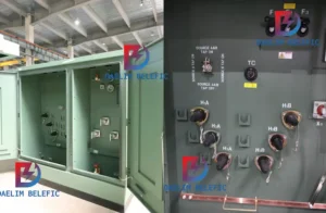
How to Choose Pad Mounted Transformer?
Table of Contents Selecting the right pad-mounted transformer requires careful consideration of several critical
ELECTRIC, WITH AN EDGE
With the increase of industrial and residential electricity consumption, the power grid system is often maintained in a high load state, and operational failures occur from time to time. The application of distributed bess battery technology in the power grid can improve the quality of power supply and enhance the stability of power grid operation. battery energy storage system bess means to connect the electricity storage device at the distribution network according to the actual demand, especially in the smart microgrid, which can maintain the load balance of electricity consumption and improve the reliability of power supply. The battery storage technology has been developed in developed countries for a long time.
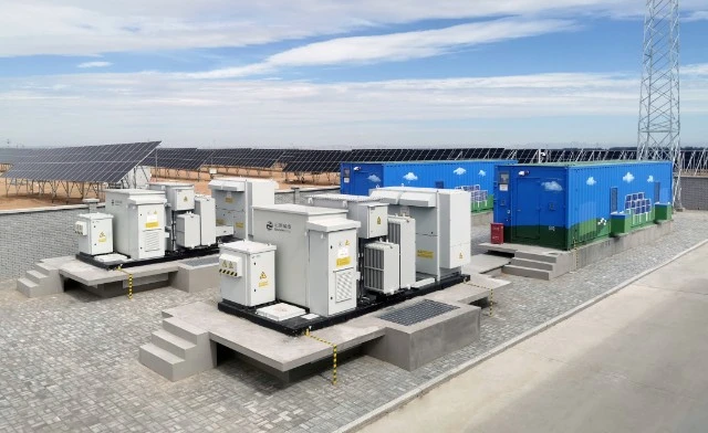
Battery storage technology is developed earlier in developed countries, and the United States has the largest number of demonstration electric storage device projects, accounting for about 50% of the global total; Japan follows, for example, the installed capacity of Nagagi Seiki Machinery Co. European countries have also invested a lot in renewable energy projects in recent years, covering a wide range of areas, including transmission and distribution, island microgrids, etc.
Choosing Daelim’s pad-mounted transformers for your Battery Energy Storage System (BESS) offers numerous advantages that make them an ideal choice for such applications:
High Quality and Reliability: Daelim has a proven track record of manufacturing high-quality transformers that meet international standards. Their pad-mounted transformers are designed to ensure reliability and long service life, making them well-suited for the demanding requirements of BESS applications.
Customized Solutions: Daelim can provide customized pad-mounted transformers tailored to your BESS requirements, taking into account factors such as power capacity, voltage levels, and specific electrical characteristics. This ensures that the transformer is optimized for seamless integration with your energy storage system.
Compact Design: Pad-mounted transformers from Daelim feature a compact design that makes them easy to install and requires minimal space. This is especially important in BESS installations where space constraints may be a concern.
Enhanced Safety: Daelim’s pad-mounted transformers are designed with safety in mind. Their sealed compartments for high-voltage and low-voltage components help reduce the risk of accidents, making them a safer choice for use in close proximity to the energy storage system and other equipment.
Efficient Cooling: Efficient cooling is critical in BESS applications to ensure the transformers can handle the continuous power flow. Daelim’s pad-mounted transformers are designed with effective cooling systems that help maintain optimal operating temperatures, ensuring high performance and reduced risk of overheating.
Compliance with Standards: Daelim’s pad-mounted transformers are manufactured in compliance with international standards, such as IEEE C57.12.34, IEEE C57.12.28, CSA C227.3 & CSA C227.4. This ensures that the transformers meet the stringent requirements for safety, performance, and quality needed in BESS applications.
After-sales Support: Daelim offers excellent after-sales support, providing customers with technical assistance, maintenance, and repair services. This ensures that your pad-mounted transformer remains in optimal condition throughout its lifespan, minimizing downtime and maximizing the efficiency of your BESS.
In summary, Daelim’s pad-mounted transformers are an excellent choice for Battery Energy Storage System applications, offering high-quality, reliable, and customized solutions that ensure the safe and efficient operation of your energy storage system.
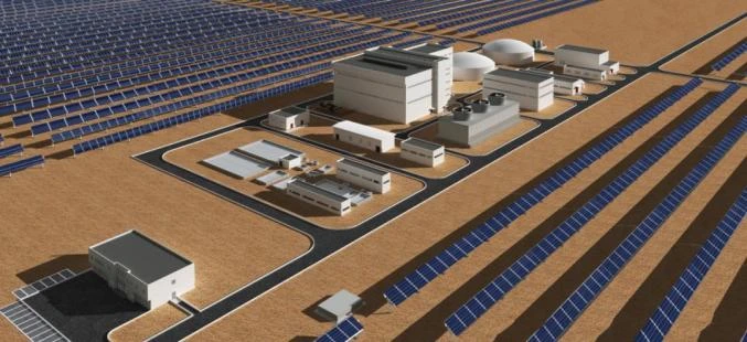
The electricity storage device is mainly used in the following fields in the ubiquitous power IOT.
(1) Power generation field
(1) Auxiliary dynamic operation. Through battery storage technology’s fast response speed, it can improve the efficiency of thermal power units and reduce carbon emission when performing auxiliary dynamic operation; avoid the damage of dynamic operation to the life of the units and reduce the cost of equipment maintenance and equipment replacement.
(2) Replace or delay the construction of new units. electric storage devices can reduce or delay the need for new generating unit capacity.
(2) Transmission field
(1) Frequency regulation. Regulate the fluctuation of frequency by instantaneously balancing the difference between load and generation. By charging and discharging the electric storage device equipment in the grid and controlling the frequency of charging and discharging, the fluctuation of frequency is regulated and the wear and tear on thermal power units is reduced.
2) Voltage support. The power system generally regulates voltage through the control of reactive power, but when the active power does cause the voltage to drop, the regulation effect is obvious with the electricity storage device.
3) Peak regulation. In the low valley of electricity consumption for pumped storage power station storage, in the peak of electricity consumption to release electricity to achieve peak shaving.
4) Standby capacity. Standby capacity is applied to unanticipated accidents of conventional generation resources. In standby capacity applications, the electricity storage device needs to be kept online and ready to discharge at all times.
(3) Power distribution field
(1) Reactive power support. The actual voltage of the line is measured by sensors, and the amount of reactive power output is adjusted, which in turn regulates the voltage of the entire line, enabling the electricity storage device equipment to be dynamically compensated.
2) Relieve line blockage. electricity storage device system is installed downstream of the blocked line, and the electricity storage device system will charge during non-blocking hours and discharge during high-load hours, thus reducing the system’s demand for transmission capacity.
3) Deferring transmission and distribution expansion. In the transmission and distribution system that meets the close equipment capacity, the electricity storage device is installed downstream of the transmission and distribution equipment that originally needs to be upgraded to delay or avoid expansion.
4) Substation DC power supply. The electricity storage device equipment in the substation can be used as a backup power supply for switchgear components, communication base stations and control equipment, and directly supply DC loads.
(3) Customer side
(1) User time-of-use tariff management. A means to help power users realize time-of-use tariff management, charging the electricity storage device system when the tariff is low; discharging it when the tariff is high.
2) Capacity cost management. Users charge the electricity storage device device during the time when their own electricity load is low; and discharge the electricity storage device device when high load is needed.
The investment hotspots of electricity storage device system include: auxiliary thermal power frequency regulation;
light battery storage power station integration; shared battery storage technology; mobile electricity storage device power truck technology; electricity storage device system for shore power; drilling electricity storage device systems; electricity storage device systems for drilling;
Subway, high-speed rail and rail transportation; power battery ladder utilization; security fire protection system; communication base station backup power utilization.
A few suggestions for the application of electric storage device system are as follows.
(1) Among all battery storage technology, except pumped storage, electrochemical electric storage device is the fastest growing and relatively mature battery storage technology, especially lithium iron phosphate and lead-carbon batteries, whose technology and economy have been commercialized. inflection point.
(2) Long life, low cost, high conversion efficiency and high safety are the necessary conditions for the large-scale application of batteries.
(3) Electricity storage device system assisted by thermal power frequency regulation in the three north, north China has appeared business opportunities, worthy of attention.
(4) containers as electricity storage device system carrier, beware of traps, should be paid attention to.
5)Battery secondary use and later recycling can be considered early layout.
(6) battery energy storage system bess as abandoned thermal power plant transformation is not lost as an effective way.
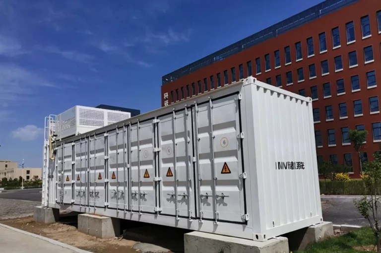
Through the demonstration application of electric storage device station, we gradually realize that the development of bess battery technology should take the road of distributed modularity. Mobile electric storage device vehicle has a small footprint, flexible and adjustable storage capacity, high modular integration, plug-and-play, easy to move, not subject to geographical constraints, flexible choice of installation site and other characteristics, has a broad application prospects.
Firstly, it can play eight advanced application functions of electric storage device system in large and distribution networks, including: peak shaving and valley filling, system frequency regulation, accident backup, reactive power support, new energy cooperation, isolated network operation, black start and power quality management.
Secondly, in technology parks, urban distribution networks, remote mountainous areas, islands and other micro-grid systems where land resources are scarce, the electric storage device can be placed at the end of the grid where the power consumption environment is harsh, taking advantage of the small footprint and quick and easy installation.
Third, it can be used as a mobile emergency power source for power rescue, field operation, disaster relief, emergency handling, temporary power connection, etc. The modular design makes it easy to move, and it can be plugged in and connected to the utility or the load to be supplied, supporting multiple units to run in parallel automatically and in a coordinated manner to meet the load demand.
Fourth, the battery used for electric vehicles and the existing bess battery station is the same technology, electric vehicle batteries can not only play a role in the car, but also as battery energy storage system bess station to give full play to the role of electric storage device in the power grid, without increasing the cost and at the same time, to achieve resource efficiency. The battery storage technology can be used in the distribution network.
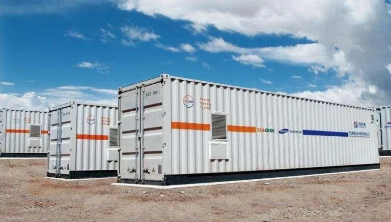
There are three major requirements for bess batteries.
First, safety: electric storage device for grid applications is theoretically safer than electric vehicle applications, but still requires expensive supporting equipment to ensure its safe use range and performance. In addition, the self-charged nature of the battery has high requirements for safe operation.
Second is the economy: battery whole life cycle cost is the main constraint, energy conversion system (PCS) and battery management system (BMS) and other equipment is relatively mature, and compression cost space is larger, the profit margin of integration is larger.
Third, convenience: electric storage device, especially battery energy storage system bess can do plug and play, convenient for users to use or integrate into the existing power system is one of the important considerations of user satisfaction.
The main application modes of bess battery in distribution network are fixed electricity storage device station and container distributed mode. Compared with the centralized electricity storage device method, the container battery energy storage system bess is expected to save 30% to 40% of the cost, greatly save the cost of plant construction, and low cost of site installation.
In order to promote the application of bess battery in the distribution network, it is necessary to carry out a comprehensive and systematic cost-benefit analysis of the electricity storage device system. By analyzing the functional role of electricity storage device system in the distribution network.
In the economic life cycle, the longer the battery life, the better the economy of electric storage device station operation is relatively. From the perspective of the operation mode, for the leasing system of one of the operation modes, the lessee should pay the annual leasing fee to the lessor, and the leasing fee can pay for the operation cost of the electric storage device station, tax, reasonable profit and recovery of the construction investment; for the peak and valley tariff system of the second operation mode.
In the current stage of lack of policy, lack of tariff mechanism, lack of emergency response incentive mechanism and lack of power quality sensitivity incentive, the adoption of mode one leasing system can reduce the operation risk and help attract investment, while enabling the electric storage device station to fully play its role in the system.
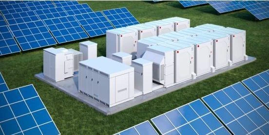
Electrochemical battery energy storage system bess is the use of rechargeable and dischargeable batteries to store electrical energy. With the continuous progress of battery technology and its cost reduction in recent years, the electrochemical electric storage device system, mainly lithium-ion battery, has been rapidly developed and widely used in engineering. Compared with lead-acid, sodium-sulfur and other bess battery systems, lithium-ion bess battery systems have many advantages such as high energy density, high conversion efficiency, low self-discharge rate, and long service life. However, lithium-ion batteries mostly use organic electrolyte with low boiling point and flammable, and the material system has high thermal value. When the battery body or electrical equipment fails, it is easy to trigger the exothermic side reaction of the battery material, which leads to thermal runaway of the battery and then evolves into a major safety accident such as burning and explosion of the electric storage device system.
Lithium batteries release energy through lithium ion embedding and dragging out in the process of use. If used improperly, thermal chemical reactions inside the battery may be induced under conditions of overcharge, high temperature, collision, etc., leading to thermal runaway occurring. If the thermal runaway propagates within the battery module, it can lead to fire and explosion accidents in the electric storage device system. The thermal runaway mechanism of Li-ion battery includes three stages:
The first stage, the initial stage of thermal runaway of lithium-ion battery. When the temperature reaches 135T, the diaphragm starts to melt and shrink, and the contact between the positive and negative electrodes causes a short circuit, thus triggering the continuous heat release of the battery. The second stage, the battery bulge stage.
At a temperature of about 250 ~ 350T, the negative electrode C6Li or precipitated lithium reacts with the organic solvent in the electrolyte and volatilizes flammable hydrocarbon gas (methane, ethane), accompanied by a large amount of heat production. The third stage, the battery thermal runaway, explosive failure stage.
In this stage, the charging state of the cathode material and electrolyte continue to occur in the violent oxidation decomposition reaction, generating high temperature and a large number of toxic gases, resulting in violent battery combustion or even explosion.
Lithium battery charging and discharging is mainly done by chemical reactions, in the process of charging and discharging will inevitably generate heat, if the heat generated by the battery itself exceeds the ability of the battery heat dissipation, lithium batteries can not get timely heat dissipation, heat will accumulate resulting in battery overheating, chemical reactions between the internal materials of the battery, such as SEI film decomposition, electrolyte decomposition, decomposition of the positive and negative electrodes, etc., the decomposition process will The decomposition process will generate a large amount of heat and gas to make the battery hot, bulging phenomenon, heat will cause the battery out of control, the battery temperature rises rapidly, resulting in internal combustion of battery materials, and the decomposition of the battery liquid will produce flammable gas, when the concentration of flammable gas reaches a certain level, an explosion will occur when encountering open flame.
At present battery energy storage system bess is mainly used ternary lithium battery and lithium iron phosphate two forms. Lithium bess battery system battery module is the design of multiple battery packs in series, which undoubtedly also increases the safety risks of lithium batteries, and once a battery performance is unstable fire, it will inevitably affect the safety of the surrounding lithium batteries, further expanding the scope of the disaster. Beijing battery energy storage system bess use is relatively safe lithium iron phosphate battery, when the lithium iron phosphate battery thermal runaway, the electrolyte will precipitate a variety of flammable and explosive gases, such as carbon monoxide, hydrogen, ethylene, methane, ethane, ethylene carbonate, ethylene carbonate, dimethyl carbonate, etc., these gases mixed with air to form an explosive mixture, will be violently exploded when it meets the source of fire.
April 6, 2021 photovoltaic battery storage power station (ESS) fire in South Korea, after the investigation of the relevant departments concluded that the fire occurred inside the electric storage device unit;
From August 2017 to October 2019, 17 of the 27 ESS fire incidents in Korea used lithium batteries manufactured by LG Chem in the incident units.
In December 2020, LG Chem announced a recall of some of its ResulOH home type electric storage device system products (ESS) in the U.S., primarily due to the risk of heat fires in the cells carried inside.
It is important to note that lithium-ion bess battery system fires have distinctive characteristics:
① intense combustion and rapid thermal spread;
② High toxicity, high smoke and dust, and high danger;
③ easy to re-ignite and difficult to extinguish. Lithium battery thermal runaway will produce toxic and combustible gases, and explosions will also occur during fire fighting, and improper disposal will also cause more casualties and losses, bringing a serious challenge to firefighting.
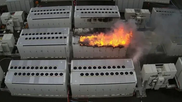
(1) First of all, the fire warning control system. Lithium battery fire start and spread, is due to the first battery single thermal runaway, through heat conduction, thermal radiation triggered by adjacent battery single thermal runaway, and eventually lead to the whole electric storage device system accident. There are three key processes in battery safety accidents: leakage, fire and explosion. The parameters that trigger thermal events are: voltage drop or generation of air pressure internal resistance, etc.
The battery body factor has long-cycle evolution characteristics, so the study of how to achieve the prediction and early warning of the evolution trend of the safety of the electric storage device system through the internal aging mechanism of the battery, the evolution of the inconsistency between batteries and the corresponding external parameter changes is the focus of the current lithium bess battery full management. Through the corresponding parameter measurement (such as electric and gas type parameters), etc., early leakage detection is carried out, and early warning is issued before thermal runaway fire and corresponding control measures are taken to provide sufficient time for external rescue. The lithium-ion battery module and battery management system should have over-temperature protection function.
battery energy storage system bess fire automatic alarm system can be set up in accordance with the individual container independent alarm area, the use of lithium battery fire detection alarm, fire alarm and linkage control signal should be real-time access to the battery energy storage system bess with a direct electrical connection to the fire Control room.
(2) followed by automatic fire extinguishing system settings. electric storage device station battery container should also be set up automatic fire extinguishing system, and according to the electric storage device station lithium battery fire characteristics, optimize the fire alarm and fire logic, according to the detector detection parameters to establish an early warning mechanism.
The first-level alarm action signal should trigger the battery container to stop, disconnect the battery side from the external electrical connection, and start the sound and light alarm;
The second-level fire detector or temperature detector action should trigger the automatic fire extinguishing system action.
Battery energy storage system bess the fire control room should be able to start the fire suppression system. electricity storage device station lithium battery automatic fire suppression system fire extinguishing agent selection is a key issue.
Common dry powder, gas and other extinguishing agents on lithium battery fire is not obvious, can not fundamentally inhibit the occurrence of fire, often re-ignition;;
Water sprinkler system technology is more mature, the cooling effect is obvious, but after extinguishing the fire will lead to battery energy storage system bess within the battery short circuit damage and can not be used normally.
Once the electricity storage device system fire, such as failure to timely extinguish the loss will rapidly expand, so the fire extinguishing device must have rapid fire extinguishing and cooling dual function to adapt.
University of Science and Technology of China has been conducting research on battery energy storage system bess lithium battery fire prevention and control, and using different fire extinguishing agents for fire prevention and control test comparison. Through the comparison of the fire suppression effect of various extinguishing agents on lithium-ion battery fire, in order to screen out the better extinguishing agents; and through the reasonable working condition design to make various extinguishing systems in lithium battery fire play a better fire suppression effect.
The following are the test effects of different extinguishing agents.
Dry powder fire extinguishing test, for a single cell, without wrapping and covering, the extinguishing agent can completely act on the cell;
Under the right conditions, the dry powder can extinguish the flame of the battery and has a cooling effect, but it cannot directly block the chemical reaction inside the battery during thermal runaway.
7JC fog fire test: fire extinguishing in the case of lithium-ion battery completely free burning, the flame is quickly suppressed, but the temperature has a tendency to rise, the application of water mist can effectively extend the thermal runaway spread time and reduce the intensity of thermal runaway. However, after stopping the spraying, sparks are generated, leading to re-ignition. Later, the battery again thermal runaway, to achieve better results, the water mist spraying time must be long enough. After using water mist to extinguish the fire, the carbon dioxide content decreases, carbon monoxide adds a lot, and the content of hydrogen, hydrogen fluoride increases, which increases the danger for fire rescue, so the lithium battery fire must be extinguished in time.
Heptafluoropropane fire extinguishing test: the pressure is relatively high when it is released, which has a shock effect on the flame and can effectively extinguish the fire.
Physical cooling while playing the role of chemical inhibition, and to a certain extent also play the role of isolation of oxygen, but after that a small amount of combustion also occurred.
Perflourohexanone fire extinguishing test: When perflourohexanone was not applied, there was an obvious jet fire process; after perflourohexanone was applied, the battery did not show an open flame, but a large amount of smoke was released and the battery did not re-ignite.
Single perflourohexanone is not ideal in cooling (less extinguishing agent), so and fine water fog combined with the test, found that when the combination of perflourohexanone and fine water fog, the peak temperature of the battery is lower Bu and faster cooling rate.
At present, all kinds of fire extinguishing agents for battery energy storage system bess fire prevention and control perflourohexanone is the most effective, not only can quickly extinguish the open fire, but also has a better heat absorption and cooling effect.
Perfluorohexanone is liquid at room temperature, after contacting the high temperature battery, it can take away a lot of heat through phase change; it can also cut off the free radicals of flame combustion and play a chemical inhibition role. If the use of perfluorohexanone and fine 7JC fog fire extinguishing system in concert with the disposal of battery energy storage system bess fire, can achieve both rapid fire extinguishing, but also cooling and inhibiting the effect.
bess battery can reduce the environmental pollution problem caused by petrochemical energy.
①Lithium-ion battery. Characterized by long service life, low self-discharge rate and high efficiency, the cathode material is usually LiCoO2, LiMn2O4, etc., and the cathode material is usually carbon material, Li4Ti5O12, etc. The parameters to measure the performance of lithium-ion batteries are capacity, energy density, lifetime and operating temperature range. When designing and using lithium-ion batteries, various factors need to be considered. The performance of lithium-ion batteries is getting better and better, and they are widely used in electric vehicles, power gridelectricity storage devices and aerospace.
②Liquid flow battery. Liquid flow battery has high capacity and the electrolyte is not inside the electrode, but stored in a specific container. When charging a liquid flow battery, the electrolyte is fed into the battery using a circulation pump. The electrodes of liquid flow battery usually use metal materials, carbon type materials and composite materials. Experiments have found that the performance of composite electrodes made by mixing carbon black and graphite at a mass ratio of 1:3 is better, and the charging and discharging efficiency of the battery can reach more than 80%. The parameters to measure the performance of liquid flow battery include capacity, power, response speed and reliability, etc. Integrating these factors, the most used is the all-vanadium liquid flow battery. This battery has high reversibility of charge and discharge, low cost, high energy efficiency and light pollution to the environment, which can be applied to large-scale electric storage device systems, microgrids and renewable energy generation. All-vanadium liquid flow batteries have high requirements for electrode materials, which must be corrosion resistant, oxidation resistant, and must meet the standards of electrical conductivity and stability. At present, the more used metal-based electrode materials are titanium-based iridium oxide, the surface of the iridium oxide does not fall off after multiple charge and discharge, and the reversibility is high. Composite class electrode material is usually polyethylene plastic and carbon powder (or graphite powder, etc.) mixed in a certain proportion, made of plastic plates to reduce costs and enhance the electrical conductivity and mechanical strength.
③Sodium-sulfur battery. Sodium-sulfur battery is a kind of secondary battery with high capacity, low cost, long life, high efficiency and easy maintenance. The positive electrode material is usually sodium metal, the negative electrode material is usually polysulfide, and the electrolyte is mainly ceramic alumina. This battery has an important role in wind power generation, peak shaving and grid electricity storage device.
The modeling of a bess battery system consists of two parts: battery pack modeling and electricity storage device converter modeling. There are many kinds of electrochemical battery models, such as equivalent circuit model, discharge model, etc. The modeling method is mainly based on the working principle and structure of the battery.
The electricity storage device converter modeling includes the circuit design and control function design of the system. Usually, the grid-connected inverter (PCS) adopts modular design, in which several standard power modules are combined into a large electricity storage device unit by series and parallel connection. The electricity storage device unit has the characteristics of large capacity and modular design, and can be connected to the grid for normal use.
The control methods of electricity storage device system usually include constant active-reactive power (P⁃Q) control, sag control and constant output voltage and frequency (V⁃F) control, all using internal loop current control. Different control methods will affect the response speed of the electricity storage device system and should be chosen flexibly according to the actual demand.
① Single cell battery modeling. The new generation vehicle partner program (PNGV) model can reflect the battery working state well, so the single battery model is established based on this model using the look-up table method. The model only considers the influence of state of charge (SOC) on parameters such as voltage, resistance and current.
②Battery modeling. In MATLAB software, using the self-contained S function, the model is built with reference to the single cell modeling method, and the SOC of the cell is calculated by the counting method.
③PCS modeling. According to the introduction of the above module structure and control method, establish the corresponding model in MATLAB software and set the initial parameters. Use the simulation model for data simulation, and compare the output results with the operation results of the real electricity storage device system. If the total power output curves of the two electric storage devices are more than 80% similar, it indicates that the modeling accuracy is high.
Distributed bess battery system can reduce the construction of electricity facilities for residents, and can also deliver electricity to industrial users at the right time according to the peak and valley conditions of electricity consumption, flexibly deploy grid resources, achieve peak and valley regulation and other functions, and improve the utilization rate of the power system. In regional power grids, distributed bess battery systems can reduce the load of transformers and other equipment in the region during peak electricity consumption to reduce unexpected accidents.
One of the functions of distributed bess battery systems is to cut peaks and fill valleys and flexibly control power generation. The difference in system capacity and deployment location leads to different adaptability to the grid. In addition, the current electric storage device system has high construction cost and relatively short lifetime, therefore, the optimization of the location and capacity configuration of electric storage device system has become the focus of research.
Firstly, the objective function is established with the parameters of comprehensive benefit, investment cost, environmental cost, and cycle cost of the electric storage device system, and the objective function is constrained with power constraint, output constraint, and tidal current constraint, and then the particle swarm algorithm is used to optimize the objective function.
The effectiveness of the proposed algorithm is verified by using the Institute of Electrical and Electronics Engineers (IEEE) ⁃14-node system, taking into account the cycle cost and comprehensive benefits of the electric storage device system, setting the number of electric storage device sites as 2, and accessing a fixed amount of electric storage devices at node 6 and node 8, respectively. The output parameters of the electric storage device system are compared before and after the addition of the electric storage device system.
It is calculated that before the inclusion of the electric storage device system, when the electricity consumption is in the low valley, the abandoned wind volume is larger, reaching 24.08%; after the inclusion of the electric storage device system, the abandoned wind rate in the same period decreases to 13.51%.
It can be seen that the addition of the electric storage device system can improve the wind power acceptance benefit; it can also reduce the peak load of electricity consumption and further ensure the safe operation of the power grid.
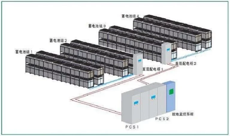
The smooth operation of the bess battery system depends on an effective bess battery scheduling system. The dispatching system can monitor the electricity storage device system in real time, and according to the real-time power consumption, it can perform peak and frequency regulation to ensure the stability of the grid. The scheduling system consists of two parts: the electricity storage device master layer and the in-place monitoring layer.
The electricity storage device master layer is equipped with servers, time alignment devices, remote devices, etc. to ensure real-time monitoring of the electricity storage device system, which can achieve the following functions:
①Provide emergency power support when an operational accident occurs in the grid;
② To realize peak, frequency and voltage regulation operations according to the actual situation of power grid operation to meet the demand for electricity;
③To track planned power generation according to demand to achieve peak shaving and valley filling;
④Improve the utilization rate of renewable energy such as wind and light energy. The in-situ monitoring layer mainly realizes the monitoring of key signals of electric storage device system, transformer, battery, etc., and regulates voltage and tracks planned power generation for electric storage device system. Both the hardware and software of the scheduling system are scalable to support access to more data points.
In most grid systems, hydro and thermal units are commonly used for FM control because they can provide unlimited energy supply, but the inherent disadvantages of hydro and thermal units (physical wear and tear, response lag, limited FM capacity, etc.) make the FM effect unsatisfactory for practical needs. People apply bess battery technology to frequency regulation control of power grids to give full play to the characteristics of fast response and high accuracy, and reduce the demand for the use of hydropower and thermal power units in power grids. Due to the limited capacity of bess battery system, the frequency regulation effect will be greatly reduced if the continuous working time is long.
Can combine the traditional hydropower and thermal power FM and bess battery system FM, using a coordinated control strategy, a clear control dead zone, in the region only enable bess battery system FM, beyond the region, while enabling the traditional FM mode and bess battery system FM. The strategy can flexibly switch the FM mode and improve the FM efficiency. bess battery system can also perform peak and voltage regulation on the grid.
In addition, the access of bess battery system can also improve the economic efficiency of the grid system and optimize the voltage quality.
(1) Insufficient thermal runaway monitoring capability of traditional sensors. Ordinary smoke and temperature sensitive fire detectors cannot penetrate inside the battery module and cannot detect the risk of thermal runaway of the battery pack in time, which is not suitable for early warning of thermal runaway of lithium-ion batteries. When the conventional detectors monitor the fire signal, the battery pack is already in a thermal runaway state, the fire has spread, and the efficiency of fire suppression is reduced.
(2) Not equipped with combustible gas detectors. The combustible gas generated by the decomposition of electrolyte released by the opening of the battery pressure relief valve forms a gathering in the confined space, which can easily form a flash explosion. If the site lacks combustible gas detection device, it cannot effectively detect combustible gas and make timely warning, which will most likely lead to a combustible gas explosion accident.
(3) Fixed fire extinguishing system is not strong in continuous fire extinguishing ability. The prefabricated electric storage device station, usually only equipped with automatic fire extinguishing system of heptafluoropropane gas, because the heptafluoropropane gas fire extinguishing system can only suppress the fire for a short period of time, but can not effectively cool down the battery pack, easy to cause the battery fire secondary re-ignition.
(4) Insufficient water source for fire-fighting in the electricity storage device station. As the site of the new electricity storage device station is restricted by the existing conditions such as the site of the substation already in operation and the water source for fire-fighting, and some of the stations in operation temporarily have no fire-fighting water source or insufficient water for fire-fighting.
(5) The fire pump room does not meet the relevant specifications. Some electricity storage device stations have not yet installed fire doors.
(6) The fire safety spacing between prefabricated modules (including battery modules and other equipment modules) is less than 3 m, and the fire doors have not been installed in some of the stations.
The fire safety distance between prefabricated compartments (including battery compartments and other equipment compartments) is less than 3 m, and there is no firewall in between.
(7) The configuration of outdoor fire hydrant is not enough. Some of the prefabricated electric storage device stations are not equipped with fire hydrants outdoors.
(8) Missing emergency evacuation signs. Emergency evacuation signs, emergency lighting and safety exits in staircases and equipment rooms have not been set, which affects the emergency evacuation of relevant personnel in case of accidents.
2.2 Irregularities in the operation and maintenance management of fire-fighting equipment and facilities
(1) Fire pumps are in “manual” mode.
(2) The configuration of fire-fighting equipment was incomplete. The site is only equipped with filtering respirator, but not with positive pressure air breathing apparatus.
(3) The fire truck access is not smooth and the rescue site is too narrow. battery energy storage system bess has debris or other equipment stacked in the fire fighting access, and the fire truck access is not smooth. At the same time, the rescue site is too close to the safety distance of the equipment compartment, which is easy to bring secondary disasters.
(4) The management of firefighting operation and maintenance was not in place. The outsourced duty personnel did not participate in fire safety training and were not licensed to work; the fire protection system did not carry out annual comprehensive testing as required.
(5)The power cables and control cables were mixed and placed without fireproof partitions between layers.
Drawing on the valve hall fire monitoring and pre-control mode of the converter station, the latest very early fire detection (such as thermal release ion fire detector) can be added to detect the abnormal state of the battery pack before thermal runaway, and the very early fire detector fire alarm linkage BNM to remove power, start the fine water mist automatic fire extinguishing system to implement water mist cooling.
Additional combustible gas detectors such as H2 and CO are installed in the battery room or prefabricated cabin, of which the number of collection points in the battery room is not less than 4; the number of collection points in the prefabricated cabin is not less than 2. Combustible gas detectors should be of infrared optical type, using explosion-proof and explosion-proof technology, with at least two communication interfaces such as hard contact and RS485. The signal of each combustible gas detector is transmitted to BMS one way, which makes judgment, issues alarm, trips, starts the fan and warning light outside the prefabricated cabin, and sends to the monitoring system; the signal of the other way is transmitted to the fire alarm controller, which is used to start the fire extinguishing system.
At present, the battery energy storage system bess prefabricated cabin mainly relies on a tank of heptafluoropropane automatic fire extinguishing system, due to its capacity and fire extinguishing characteristics, can suppress the battery fire, but can not completely extinguish the fire, prone to re-ignition, so it is necessary to enhance the continuous fire extinguishing capacity, can be in the prefabricated cabin battery energy storage system bess system bess installed with fine water mist automatic fire extinguishing system, and in the prefabricated cabin to increase the fine water mist nozzle. The start of the fine water mist fire extinguishing system should be in line with the “first power off, after the fire” requirements. Fire extinguishing system control battery energy storage system components after receiving the warning signal or fire signal, according to the established fire extinguishing strategy, automatically start the fire extinguishing system.
Install more outdoor fire hydrants to facilitate the rescue fire extinguisher to replenish water in time in case of battery energy storage system bess fire; increase the firewall between the prefabricated compartments of prefabricated battery energy storage system bess (including battery compartment and other equipment compartments) to enhance the fire safety between the equipment compartments. distance, to avoid the situation of “burning camp”. Each station is equipped with 2 sets of positive pressure firefighting air breathing apparatus for fire emergency disposal.
Check whether the battery energy storage system bess project implementation department has completed the fire audit, acceptance and record work of the electricity storage device station. Fire protection facilities engineering design and construction enterprises, whether they have the corresponding fire protection facilities engineering design and construction qualification issued by the state construction department. battery energy storage system bess fire protection duty personnel should hold the fire protection facilities operator qualification certificate of junior level or above, and can skillfully operate fire protection facilities. Entrust a unit with professional fire protection testing qualification to conduct at least one comprehensive inspection and test of the fire protection facilities of battery energy storage system bess every year and issue a fire protection facilities testing report.
Clarify the maintenance and management of battery energy storage system bess fire protection facilities, the management personnel and their work responsibilities, and carry out daily maintenance and management of fire protection facilities in strict accordance with relevant regulations to ensure that the fire protection facilities are intact and effective. Clarify the fire protection operation and maintenance responsibilities of battery energy storage system bess outsourcing operation and maintenance manufacturers, and require the duty operation and maintenance personnel to participate in fire safety training and hold the fire protection facility operator qualification certificate of primary level or above. After the fire fighting facilities are put into use, they should be set to “automatic operation” and the valves and battery energy storage system components should be in normal working condition, and the fire fighting facilities should not be shut down without authorization. Actively carry out fire extinguishing, emergency plans and drills, should develop fire extinguishing system operating procedures and emergency plans, and organize emergency plan drills.
In order to better standardize and guide the operation, overhaul and acceptance of battery energy storage system bess on the grid side, it is necessary to organize the preparation of battery energy storage system bess general operation procedures, overhaul procedures, equipment acceptance and fire safety management and other aspects of the operation and maintenance overhaul system, and sound battery energy storage system bess safety production management system.
The common types of battery energy storage system bess include nickel-metal hydride electric storage batteries, lead storage electric storage batteries, lithium-ion electric storage batteries, liquid flow electric storage batteries, etc. Due to the different battery structures and compositions, the performance of different types of battery energy storage system bess batteries also differs. An in-depth understanding of the characteristics of various battery energy storage system bess batteries is necessary to take full advantage of their performance.
NiMH battery is a kind of early development, technology is more mature electric storage batteries, initially designed to replace the cadmium-nickel battery as the second generation of space electric storage device power. The energy density of NiMH battery can reach 95 Wh/kg, which can realize fast charging and discharging, excellent low-temperature performance and cycling performance, and can be cycled 40,000 times when working in LEO satellites with a discharge depth of 40% of DOD.
According to the way of hydrogen storage, NiMH batteries can be divided into high-voltage NiMH batteries and low-pressure NiMH batteries. The main difference between the two is that high-voltage NiMH batteries use high-pressure cylinders to store hydrogen directly while low-pressure NiMH batteries use hydrogen storage alloy to store hydrogen. In terms of performance, high-voltage NiMH batteries have higher energy density and better cycling performance, but the use of cylinders for hydrogen storage poses a greater safety risk. Therefore, high-voltage NiMH batteries are usually used in synchronous orbit satellites as electricity storage device power. The famous American Hubble Telescope was launched in 1990 using a NiMH battery pack with a capacity of 83 A-h.
In contrast, the safety performance of low-pressure NiMH batteries is greatly improved due to the use of alloy hydrogen storage, but the introduction of hydrogen storage materials causes an increase in overall mass, resulting in a corresponding decrease in energy density. Based on the characteristics of high safety and long cycle life, low-voltage NiMH batteries were once widely used in consumer electronics such as cell phones, notebook computers and video cameras. In the field of electric vehicles, NiMH batteries are also one of the most mature secondary batteries. The Prius hybrid car designed by Toyota of Japan uses low-voltage NiMH batteries. This model was the first truly marketable hybrid car, and still maintains high sales today.
Nickel-metal hydride battery is still one of the most mature secondary batteries, with high cycle life, large rate charge and discharge performance and other advantages in the aerospace electric storage device, consumer electronics, electric vehicles are widely used. However, because its theoretical capacity is not as good as lithium-ion batteries and has a memory effect and other shortcomings, in the long run, NiMH batteries will face the challenge of lithium-ion batteries as the main secondary battery.
Lead battery is the first commercialized secondary battery, and is also the most widely used battery product. In terms of structural composition, lead battery consists of positive electrode (lead dioxide, PbO2), negative electrode (metallic lead, Pb), electrolyte (sulfuric acid, H2SO4), spacer and battery case (including connecting parts) and other parts. The manufacturing and recycling process of lead battery is extremely mature, so that there is no leakage of lead in theory during its production, use, recycling and reuse, which minimizes the impact of lead battery on the environment. Compared with other batteries, lead batteries still have some unparalleled excellent performance:
1) Simple structure and low cost.
2) High voltage of single cell (2 V).
3)Excellent performance of large rate discharge, so it is widely used as the starting battery for automobiles, tractors, motorcycles, etc.
4)Wide working temperature range, in -40~50℃ can work normally.
5)Excellent shallow charging and discharging performance, suitable for new energy electric storage device, peak-to-valley and frequency regulation of power grid.
(6) High safety, very few misfires and explosions, so it can be made into a large-capacity battery pack.
Based on the above advantages, lead battery is still the most widely used battery, its application range mainly includes
(1) starting power for automobiles, tractors, etc;
(2) battery storage for solar and wind, battery storage system for solar and other new energy generation storage;
(3) uninterruptible standby power supply (UPS) for data centers, computers, and large instruments and equipment
(4) small electric vehicles, engineering vehicles and other power supply.
Due to the advantages of low cost, high safety, wide operating temperature range and excellent shallow charge and discharge performance, lead batteries have been used in power systems. As of 2018, the share of lead batteries in the global installed capacity of electrochemicalelectricity storage device is 5.9%.
The biggest disadvantages of lead batteries are mainly two:
(1) The energy density of lead batteries is low, with a theoretical value of 170 Wh/kg and an actual value of less than 50 Wh/kg, and the actual energy density is less than 1/3 of that of current commercial lithium-ion batteries;
(2) The cycle life of lead battery is relatively low, only about 1/3 of that of lithium-ion battery, and the actual service life is only about 2 years when it is used to shift peaks and fill valleys.
The introduction of battery management system (BMS) has effectively improved the service life of lead batteries and reduced the cost of use, but the intrinsic defect of low energy density has limited the further large-scale application of lead batteries. At present, the proportion of lead batteries in the installed scale of power systems is decreasing and gradually being replaced by new electrochemical systems such as lithium-ion batteries. However, lead batteries are simple to maintain and highly reliable, and can still be useful in the construction of electric storage devices in remote areas, backup power for large equipment and uninterrupted power supply.
Lithium ion electric storage batteries were first commercialized by Sony in 1992. Compared with other commercialized secondary electric storage batteries, lithium-ion electric storage batteries have the advantages of high energy density, long cycle life, and no memory effect, and are the most promising and feasible route for electric storage devices.
The diagram shows the operation of lithium-ion electric storage batteries: during charging, lithium ions (Li+) are removed from the positive electrode and migrate to the negative electrode side and are embedded in the negative electrode material layer; during discharging, Li+ is removed from the negative electrode and migrate to the positive electrode and are embedded in the positive electrode material. It can be seen that the storage and release of electric energy in Li-ion electric storage batteries is realized by the migration of Li+ between the positive and negative electrodes, and this reciprocal migration is like the reciprocal movement at the two ends of a rocking chair, so Li-ion electric storage batteries are also called “rocking chair”. electric storage batteries”.
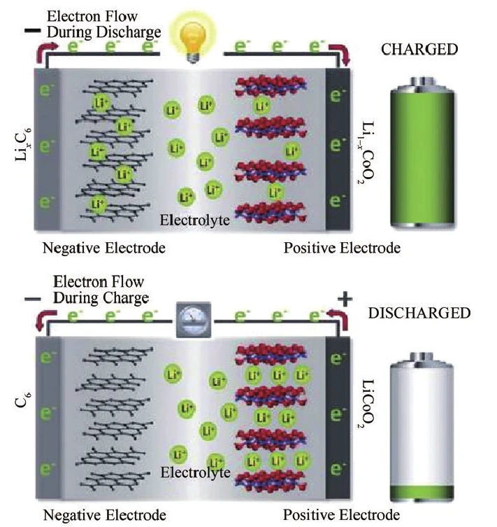
From the viewpoint of working mechanism, Li-ion electric storage batteries are a large class of electric storage batteries that use lithium ion migration between positive and negative electrodes to achieve charging and discharging.
Theoretically, materials that can reversibly de-embed lithium ions have the potential to be used as electrode materials for lithium ion electric storage batteries. At present, there are various cathode materials such as lithium cobaltate, lithium iron phosphate, lithium nickelate and ternary materials, and negative electrode materials such as graphite and silicon-carbon, which have been commercially available. Different electrode materials will give lithium ion electric storage batteries different operating characteristics. For example, lithium iron phosphate cathode materials have the advantages of good high temperature performance, excellent cycling performance and good safety; ternary cathode materials represented by nickel cobalt manganese and nickel cobalt aluminum have higher operating voltage and higher capacity; lithium cobalt acid cathode materials have the advantages of smooth discharge platform and excellent high current performance. It is based on the above characteristics, through the design of electrode materials, electrolyte, electric storage batteries structure, you can get power type, energy density type, reserve type and other different characteristics, different uses of lithium-ion electric storage batteries.
At present, the energy density of commercial lithium-ion electric storage batteries is 150~250 Wh/kg, which is much higher than all the current commercial secondary electric storage batteries. The energy density and cycle life of Li-ion electric storage batteries can be further improved through structural design and development of new materials.
Lithium-ion electric storage batteries are the most comprehensive secondary electric storage batteries, which have been widely used in portable electronic devices and gradually replaced lead-acid and nickel-hydrogen electric storage batteries as power electric storage batteries. electric storage batteries are used in electric vehicles. In the power system, lithium-ion electric storage batteries have a very broad application potential in AGC frequency regulation, renewable energy generation and peak-to-valley regulation.
The liquid flow battery was originally supported by NASA and proposed in the 1970s as a secondary bess battery device.
Unlike other traditional secondary batteries (such as cadmium-nickel and lithium-ion batteries) in which the electrode materials are permanently enclosed in the battery casing, the cathode and anode reactants of liquid flow batteries are liquid electrolytes that are stored separately and controlled in flow by a pump body. These electrolytes are both the active material for the electrode reaction and the carrier for ion transport.
By controlling the amount of liquid electrolyte storage and flow rate, the capacity and output power of the electric storage device can be adjusted. The liquid flow battery can achieve 100% deep discharge without damaging the battery, and the battery can be “instantly charged/discharged” by electrolyte replacement. Based on the above advantages, liquid flow battery has very high design freedom and flexibility.
Another feature of liquid flow batteries is that the active electrolyte is an aqueous solution, making the battery system free from the risk of fire and highly safe, making it ideal for the construction of large electric storage device stations.
The all-vanadium liquid flow battery is one of the most promising liquid flow batteries and has already received initial commercial application.
However, the biggest obstacle that currently limits the large-scale application of liquid flow batteries is their expensive cost. The cost of ion-exchange diaphragms can be as much as 55% of the cost of the battery.
At present, the most commonly used diaphragm with the best performance is the Nafion membrane produced by DuPont in the U.S. The high technical threshold causes it to have almost no substitutes, making the development of liquid flow batteries in China seriously limited. In addition, the use of Nafion membrane as a diaphragm will have the phenomenon of ion and water permeation migration, which will cause the failure of the battery.
The more mature liquid flow battery, vanadium liquid flow battery, requires a large amount of toxic vanadium solution, which poses certain environmental problems. In addition, the sealing technology of the battery and the development of high-efficiency electrode materials are to a certain extent limiting the large-scale application of liquid flow batteries.
All in all, due to technical and cost constraints, liquid flow batteries are still in the early stage of commercial application and there are many technical problems that need to be solved. However, the advantages of high safety and good flexibility of liquid flow battery make it one of the most promising choices in the field of electric storage device.
Fuel cell is a device that directly converts the chemical energy of fuel and oxidizer into electrical energy. Unlike other secondary battery charging and discharging modes of operation, the fuel cell continuously inputs fuel (hydrogen, methane, etc.) and oxidizer (air, oxygen) to continuously and steadily output electrical energy during operation. From this perspective, fuel cells are similar to internal combustion engines as a power generation technology. Compared with thermoelectric units, fuel cells have many unparalleled advantages:
1) High efficiency. The fuel cell converts the chemical energy of fuel into electricity directly through electrochemical reaction, which is not limited by the Carnot cycle. Therefore, the energy conversion efficiency can reach 100% in theory, and the actual efficiency has reached 60%~80%, which is more than two times of ordinary heat engines.
2) Environmentally friendly. The fuel gas used in fuel cells includes hydrogen, methane, methanol, natural gas, etc. Theoretically, there is no production and emission of nitrogen oxides and sulfide when working, and the carbon dioxide emission is also more than 40% lower than that of coal power generation, effectively reducing air pollution while also reducing greenhouse gas emissions.
3) Simple structure. The fuel cell structure is simple and has no friction or rotating parts, so the working noise is low. The simple structure also helps to realize the miniaturization and householdization of fuel cells.
There are many ways and types of fuel cells. According to the difference of electrolyte, fuel cells can be classified into proton exchange membrane fuel cell (PEMFC), alkaline fuel cell (AFC), direct methanol fuel cell (DMFC), molten carbonate fuel cell (MCFC), phosphoric acid fuel cell (PAFC), solid oxide fuel cell (SOFC), etc.
Although the operating conditions of each fuel cell are different, the overall structure and operating mechanism are basically similar, i.e., the positive and negative active substances are stored separately and the electrical energy is output by electrochemical reaction at the electrolyte interface (e.g., proton exchange membrane). In this regard, fuel cells are more similar in structure to liquid flow cells.
Fuel cells have found practical applications in aerospace, military, electric vehicles, and distributed power generation systems. The ENE-FARM type proton exchange membrane fuel cell introduced by Panasonic Corporation of Japan and the small solid oxide fuel cell system developed by Tokyo Gas Company target the 1 kW-class household market and have been initially commercialized. These distributed fuel cells can meet the demand for electricity for daily life of residents, and can also be connected to the grid to reduce the pressure on the power grid, reduce the loss of power delivery to the grid and improve the efficiency of energy use. In addition, fuel cell systems also have great potential for border and island power supply.
Download Resource

Table of Contents Selecting the right pad-mounted transformer requires careful consideration of several critical
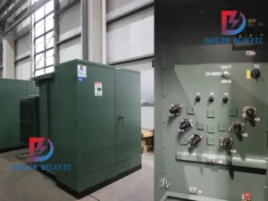
The primary function of the pad mounted transformer is to serve as a critical distribution
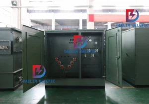
A pad mounted transformer operates through electromagnetic induction, serving as a crucial distribution component that
After filling in the contact information, you can download the PDF.