
ELECTRIC, WITH AN EDGE
The 10KV distribution transformer has a variety of models and styles because of the different output voltages and usage scenarios on both sides. The following will specifically introduce 10KV distribution transformers of various styles and usage scenarios.
In an era where energy demands are constantly evolving, the role of a 10 kv transformer, or 10 Kv Distribution Transformer, is pivotal in shaping the future of energy. From ensuring safety and energy efficiency to playing a crucial part in renewable energy projects, this vital piece of equipment serves diverse purposes across various industries. This comprehensive guide delves into the different aspects of a 10 kv transformer, answering common questions and shedding light on its significance in modern energy systems. Explore the dynamic world of transformers and discover how they contribute to a more reliable and sustainable energy landscape.
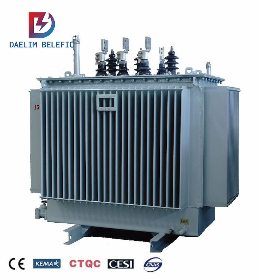
Although the 10 KV transformer has a variety of styles. But from the overall structure, they are mainly divided into 10 kv oil-immersed transformers and 10 kv dry-type transformers.
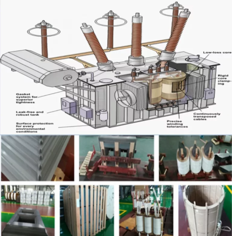
Oil-immersed distribution transformers can be divided into main body, oil conservator, insulating bushing, tap switch, protection device, etc. according to their structure.
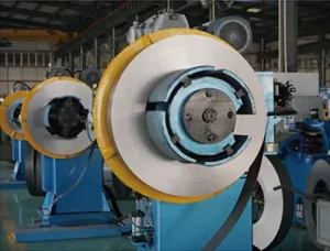
Daelim usually uses cold-rolled silicon steel sheets coated with insulating varnish to produce iron cores in the production of 10 kv transformers. The thickness of this cold-rolled silicon steel sheet is 0.35mm or 0.5mm.
Calculation Method of the Number of Turns of Power Transformer Core
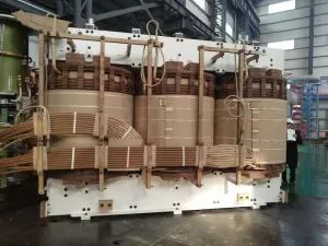
Winding refers to the part of the circuit covered on the iron core column of 10 kv transformers. The material of this circuit part is usually copper wire. Wrap the copper wire around the iron core column to form a circuit cover.
The winding is sleeved on the iron core column of the transformer, the low-voltage winding is in the inner layer, and the high-voltage winding is sleeved in the outer layer of the low-voltage winding.
To facilitate insulation.
What are the types of transformer windings ? What are the types of concentric windings?
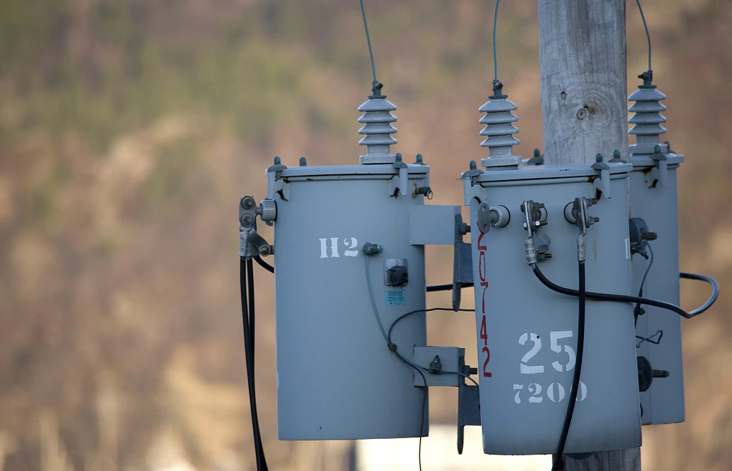
The composition of transformer oil is very complex, mainly composed of naphthenic hydrocarbons, alkanes and aromatic hydrocarbons. Transformer oil plays two roles in distribution transformers: one is to insulate between transformer windings and windings, windings and cores and oil tanks. effect. The second is that the transformer oil will generate convection after being heated, which will radiate heat to the transformer core and windings. Commonly used transformer oil has three specifications, No. 10, No. 25, and No. 45. The label indicates the temperature when the oil starts to solidify below zero. For example, “No. 25” oil means that this oil starts to solidify at minus 25°C.
Three functions and performance requirements of transformer oil
The location of the oil drum is usually above the 10 kv transformer. Daelim can design oil drums of different capacities according to different transformer requirements.
When the transformer is affected by temperature, expands or shrinks. The oil drum will fill the iron core and windings with oil through the oil pipeline. This can ensure that the core part of the 10 KV transformer is always in an insulated state. Ensure the smooth operation of the 10 KV transformer.
10 KV transformers are equipped with an oil standard, which is also a standard gauge for oil level. This is to allow the staff to better observe the size of the oil in the drum.
It is the main insulation device outside the 10 kv transformer box, and most of the 10 kv transformer insulation sleeves use porcelain insulation sleeves.
The 10 kv transformer leads the high and low voltage winding leads of the transformer from the oil tank to the outside through the high and low voltage insulating bushings, so that the transformer windings are insulated from the ground (shell and core), and it is also the main part of the fixed lead connecting with the external circuit.
The high-pressure porcelain bushing is relatively tall and the low-pressure porcelain bushing is relatively short.
A device for changing the tap of the high-voltage winding of a transformer to adjust the tap position, which can increase or decrease the number of turns of the primary winding to change the voltage ratio and adjust the output voltage.
After the transformer is out of operation and disconnected from the grid, the position of the tap switch is manually changed, and the output voltage adjustment is called no-load voltage regulation.
The gas relay is installed between the connecting pipe of the transformer oil tank and the oil conservator, and is connected with the control circuit to form a gas protection device.
The upper contact of the gas relay and the light gas signal form a separate circuit, and the lower contact of the gas relay is connected to the external circuit to form a heavy gas protection.
The heavy gas action causes the high-voltage circuit breaker to trip and send out the heavy gas action signal.
The riot tube is a safety protection device for the transformer , Installed on the large cover of the transformer, the anti-riot tube communicates with the atmosphere, the heat will vaporize the transformer oil in the event of a fault, and trigger the gas relay to send an alarm signal or cut off the power supply to avoid the fuel tank from bursting. The distribution transformer is divided into indoor and outdoor according to the installation location.
We will classify 10 kV transformers according to the installation location, cooling method, and the number of phases.
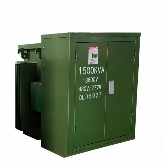
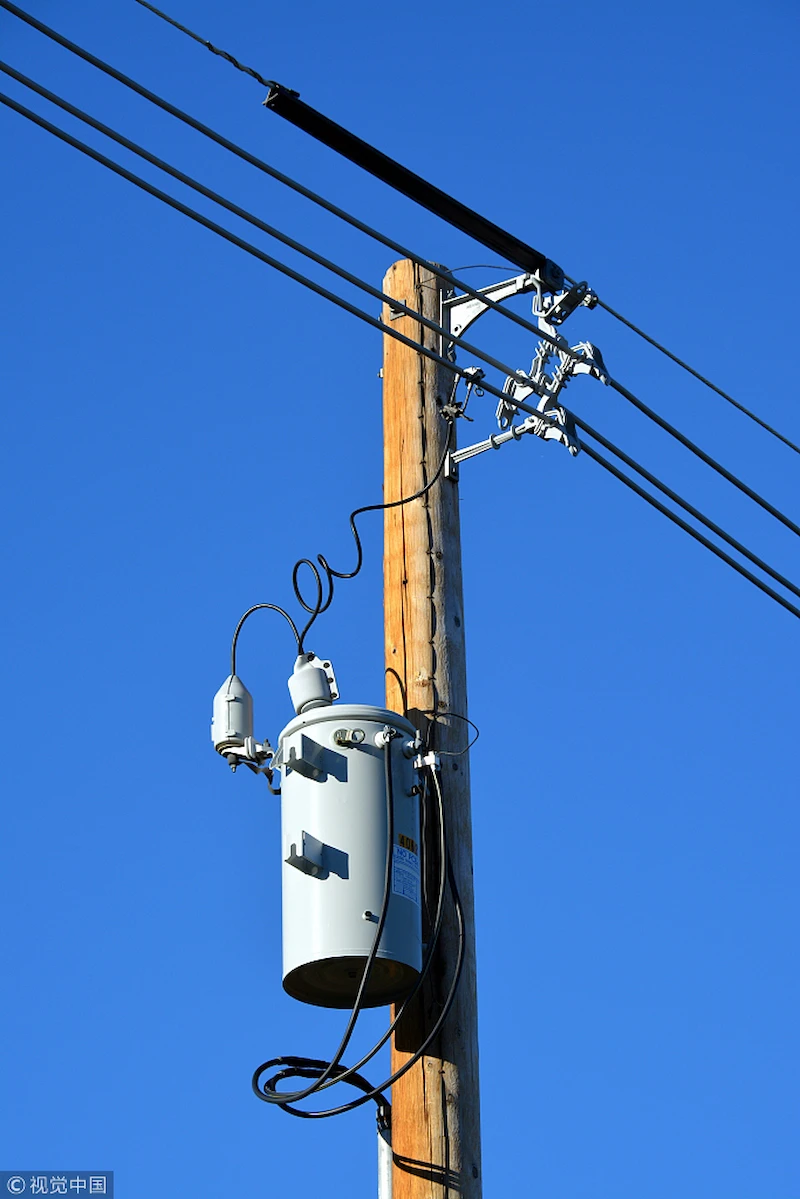
According to the difference of installation position, 10 Kv transformer can be divided into electric pole transformer and pad-mounted transformer.
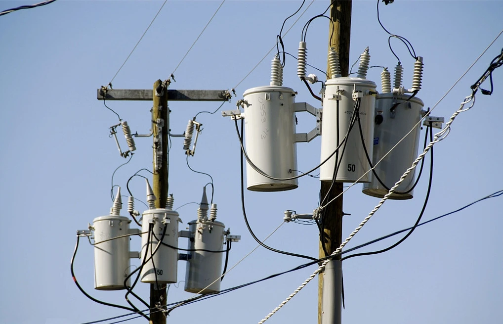
Electric Pole Transformer refers to a distribution transformer installed on a cement pole. The rated power range of 10 Kv pole transformer is 5~167 KVA. It is also divided into Overhead Completely Self Protected (CSP) Electric Pole Transformer and Overhead Conventional Electric Pole Transformer.
Since it only needs to be mounted on the concrete column, compared to other transformers, Electric Pole Transformer has the smallest footprint.
Because it is installed in the air, compared to the Pad-mounted transfomer, Electric Pole Transformerd does not need to install guardrails around it.
At the same time, Electric Pole Transformer does not need to be grounded, which improves its safety. Leakage and other accidents are not easy to occur.
The following will describe the 10 Kv Electric Pole Transformer in detail from the dimensions, specifications, working principles, features, and other parts. Pls, check it.
Learn more about the fundamentals of Electric Pole Transformers.
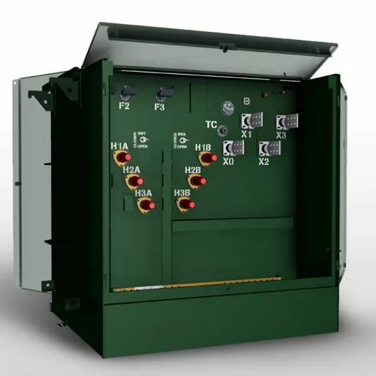
The main switch on the low-voltage side of the Pad-mounted transformer generally adopts three types of automatic switches, DZl0, DWl0, and DWl5.
The electrical appliances used on the low-voltage side branch include BM and BT series fuses and DZ and DW series automatic switches.
When the Pad-mounted transformer capacity of the substation is 200-630kVA, DWl0 or DWl5 is used as the low-voltage main switch. When the capacity exceeds 800kVA, the DWl5 switch should be used as much as possible.
In the following link, I will describe the pad-mounted transformer in detail. 14 FAQs about it.
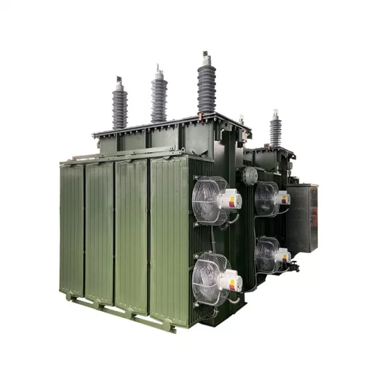
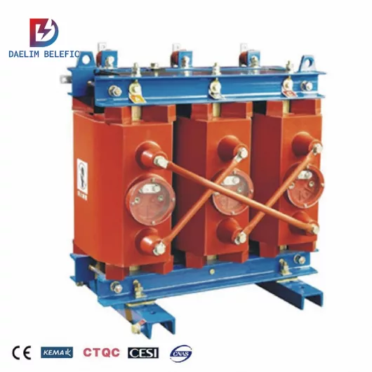
According to the cooling method of the core part, 10 kv transformer can be divided into: 10 kv oil-immersed transformer and 10 kv dry-type transformer.
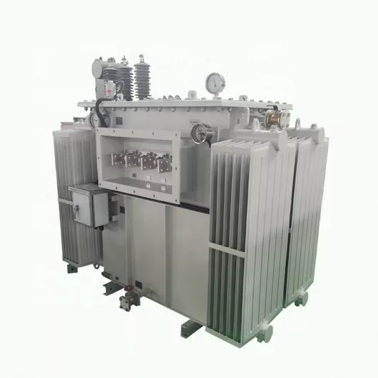
The 10 KV oil-immersed distribution transformer is an important part of the medium-scale mining area distribution network. Because of its compact structure, small size and easy movement, it has also been purchased by many Bitcoin mining farms. The advantages of low noise and strong overload capacity also make it possible to be distributed in residential communities.
10 KV oil-immersed distribution transformers can be divided into enclosed oil-immersed transformers and oil-storage oil-immersed transformers.
The oil conservator attached to the oil storage type oil-immersed transformer can help reduce the contact between the transformer oil and the air. Prevent deterioration of transformer oil. Affect the service life of the transformer.
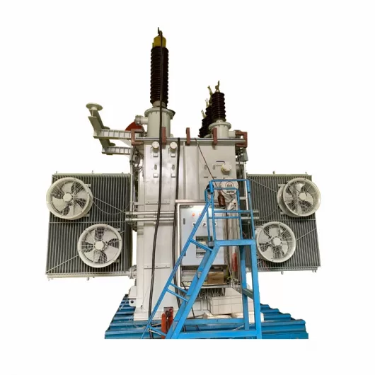
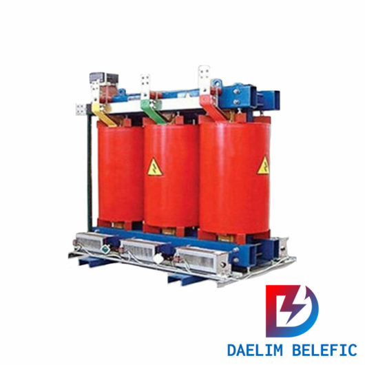
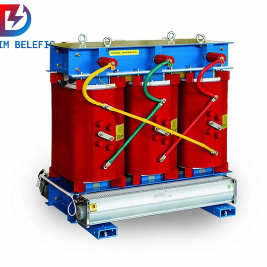
10 kv Three Phase Epoxy-resin Dry-type Transformer is mainly suitable for heavy-duty centers.
Selection And Maintenance of 10 kV Dry-type Transformer
It mainly stabilizes the internal temperature of the transformer by installing air-cooled equipment in the transformer. Because there is no transformer oil. Therefore, it has outstanding fire resistance compared with other transformers. It can be applied to areas with special fire protection requirements.
The volume of the 10 kv Three Phase Epoxy-resin Dry-type Transformer is small, and the partial discharge quality is low. Rated power: 50~2500 kva. And her no-load loss is small, and it is economical.
In the link below, you will see all the information about the dry-type transformer in full. Including its internal structure, working principle, sizes and other content.
pls, check it.
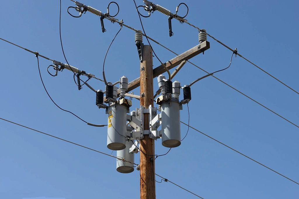
In the early days, people mostly used three-phase four-wire power distribution technology to complete power supply in residential areas. This caused the serious power loss.
In order to achieve energy-saving goals. More and more communities are equipped with single-phase transformers. The 10KV transformer single phase can directly transmit 10 kV high voltage to every household.
The use of 10 kV transformer single phase reduces the line loss caused by power transmission. Conducive to improving economic efficiency.
10 kV transformer single phase has the advantages of small size and lightweight. Therefore, the 10 kV transformer single phase can reach the load center as far as possible.
This shortens the transmission radius of the low-voltage power grid and greatly reduces power loss.
The 10 kV transformer single phase is usually installed on a concrete pole with a length of 12 meters to 15 meters. It occupies a small area, so its use is less affected by topographical factors.
Taking power with a capacity of 50kVA as an example, the S9 three-phase load has a phase load power consumption of 170W, but the no-load consumption of the single D12 model is 110W, which is 35% lower than that of the S9 model.
First, the power distribution room uses 10kV lines to feed power to residential users or commercial offices.
Second, single-phase transformers are generally connected to households with low-voltage lines by hanging poles. This can shorten the length of the entrance line. Generally, the length of the entrance line cannot exceed 20 meters.
Third, the capacity of single-phase transformers should be selected reasonably to match the maximum power consumption of residential buildings, forming a situation of densely distributed small capacity.
Fourth, the electricity meter is a device for centralized recording of the amount of electricity used. It should be centrally installed in the meter box at the appropriate location in the corridor of the residential building, so that one meter per household can be accurately counted.
When the electricity load in the 10kV distribution network is in a normal state, the current situation of excessive line loss can be reduced by reducing the equipment capacity. The load of the low-voltage distribution network changes at any time, which will occur with the time of electricity use, seasons, etc. Change.
In the 10kV distribution network design process, a single-three-mixed distribution transformer installation plan is generally adopted. This plan can be configured with one or more 10kv single-phase distribution transformers. According to the specific changes in the electrical load and the low-voltage power grid The operation mode of the single-phase transformer determines the capacity requirement of the single-phase transformer so that a more suitable transformer is selected for power supply.
The 10 kv single-phase transformer is designed to provide users with more stable electrical energy products and reduce various problems caused by excessive electrical load. There are usually three ways to install single-phase transformers, depending on the situation. Choose the appropriate installation method:
When wiring a 10 kv single-phase transformer, there are mainly two schemes: manual lay-up and disassembly method and knife-switch conversion method.
The following are the data parameters of 10 kv oil-immersed three-phase transformer, 10 KV Sealed Amorphous Alloy Transformer, 10KV Class Three Phase Epoxy-resin Dry-type Transformer, Rated power and Loss.
| Rated Power (KVA) | High Voltage (KV) | Low Voltage (KV) | Connection Symbol | Short Circuit Impendence | Loss(W) | No Load Current | |
| No-load Loss(W) | On-load Loss(W) | ||||||
| 30 | 4.16 6 6.3 7.2 10 10.5 11 or others | 0.208 0.4 0.6 | Dyn11 Yyn0 | 4 4.5 5 | 100 | 600 | 2.1 |
| 50 | 130 | 870 | 2 | ||||
| 63 | 150 | 1040 | 1.9 | ||||
| 80 | 180 | 1250 | 1.8 | ||||
| 100 | 200 | 1500 | 1.6 | ||||
| 125 | 240 | 1800 | 1.5 | ||||
| 160 | 2840 | 2200 | 1.4 | ||||
| 200 | 340 | 2600 | 1.2 | ||||
| 250 | 400 | 3050 | 1.2 | ||||
| 315 | 480 | 3650 | 1.1 | ||||
| 400 | 570 | 4300 | 1 | ||||
| 500 | 680 | 5150 | 1 | ||||
| 630 | 810 | 6200 | 0.9 | ||||
| 800 | 980 | 7500 | 0.8 | ||||
| 1000 | 1150 | 10300 | 0.7 | ||||
| 1250 | 1360 | 12000 | 0.6 | ||||
| 1600 | 1640 | 14500 | 0.6 | ||||
| 2000 | 1940 | 17140 | 0.6 | ||||
| 2500 | 2300 | 20260 | 0.5 | ||||
| Rated Power (KVA) | High Voltage (KV) | Low Voltage (KV) | Connection Symbol | Short Circuit Impendence | Loss(W) | No Load Current | |
| No-load Loss(W) | On-load Loss(W) | ||||||
| 30 | 6.3 6.6 10 10.5 11 or others | 0.4 | Dyn11 Yyn0 | 4 | 33 | 600 | 1.7 |
| 50 | 43 | 870 | 1.3 | ||||
| 63 | 50 | 1040 | 1.2 | ||||
| 80 | 60 | 1250 | 1.1 | ||||
| 100 | 75 | 1500 | 1 | ||||
| 125 | 85 | 1800 | 0.9 | ||||
| 160 | 100 | 2200 | 0.7 | ||||
| 200 | 120 | 2600 | 0.7 | ||||
| 250 | 140 | 3050 | 0.7 | ||||
| 315 | 170 | 3650 | 0.5 | ||||
| 400 | 200 | 4300 | 0.5 | ||||
| 500 | 240 | 5150 | 0.5 | ||||
| 630 | 4.5 | 320 | 6200 | 0.3 | |||
| 800 | 380 | 7500 | 0.3 | ||||
| 1000 | 450 | 10300 | 0.3 | ||||
| 1250 | 530 | 12000 | 0.2 | ||||
| 1600 | 630 | 14500 | 0.2 | ||||
| 2000 | 5 | 750 | 17400 | 0.2 | |||
| 2500 | 900 | 20200 | 0.2 | ||||
| Rated Power (KVA) | High Voltage (KV) | Low Voltage (KV) | Connection Symbol | Short Circuit Impendence | Loss(W) | No Load Current | |
| No-load Loss(W) | On-load Loss(W) | ||||||
| 50 | 6 6.3 6.6 10 10.5 11 13.2 or others | 0.4 | Dyn11 Yyn0 | 4 6 | 270 | 990 | 2 |
| 100 | 400 | 1570 | 1.8 | ||||
| 160 | 540 | 2120 | 1.4 | ||||
| 200 | 620 | 2520 | 1.4 | ||||
| 250 | 720 | 2750 | 1.4 | ||||
| 315 | 880 | 3460 | 1.2 | ||||
| 400 | 970 | 3980 | 1.2 | ||||
| 500 | 1160 | 4880 | 1.2 | ||||
| 630 | 1340 | 5870 | 1.0 | ||||
| 800 | 1520 | 6950 | 1.0 | ||||
| 1000 | 1760 | 8120 | 0.8 | ||||
| 1250 | 2090 | 9690 | 0.8 | ||||
| 1600 | 2450 | 11730 | 0.8 | ||||
| 2000 | 3320 | 14450 | 0.6 | ||||
| 2500 | 4000 | 17170 | 0.6 | ||||
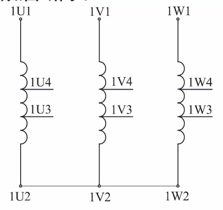
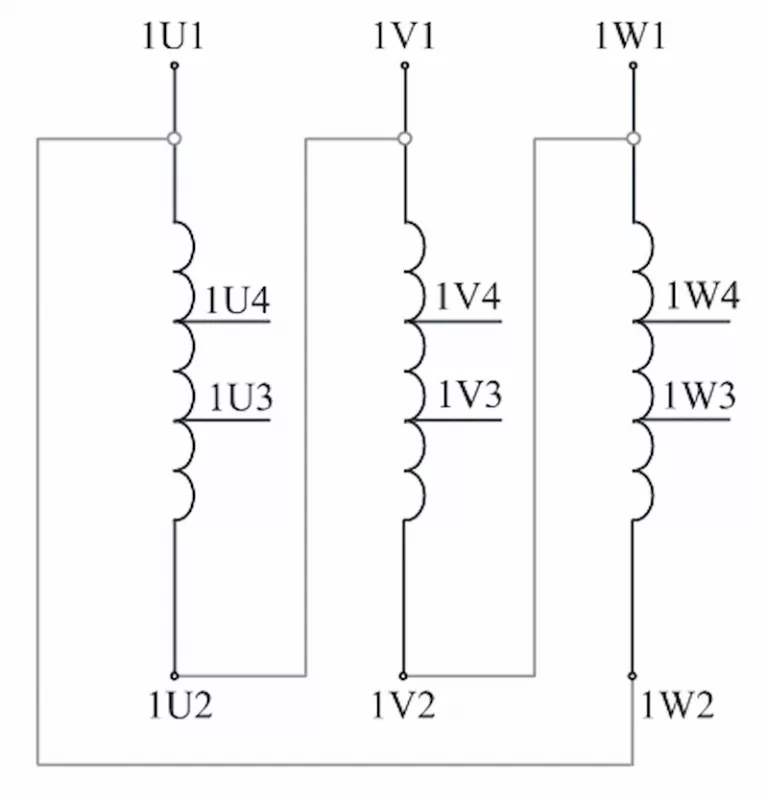
There are two main ways to connect 10 kV transformer 3 phase. One is the Wye connection. One is the delta connection.
Connecting to the three-phase power supply A, B, C corresponds to 1U1, 1V1, 1W1 . The three taps of the remaining windings of each phase are respectively connected to the terminal of the tap changer. Turn the tap changer by hand to Set it to Ⅰ position. At this time, the tap switch connecting piece is connected to 1U2, 1V2, 1W2. If it is connected to a 10 kV tap with a voltage of 10 500 V, the corresponding low-voltage output voltage will be lower, which is 380 V; set it to Ⅱ In gear, the taps connected to the tap changer connecting piece are 1U3, 1V3, 1W3, respectively, the 10 kV tap voltage is 10 000 V, and the low-voltage output voltage is 400 V; when it is placed in the Ⅲ gear, the tap connected to the tap changer connecting piece They are 1U4, 1V4, and 1W4 respectively. The 10 kV tap voltage is 9 500 V, and the low-voltage output voltage is 420 V.
The delta connection of the primary windings of the three-phase transformer is to connect the head and ends of the primary windings to each other to form a closed loop, and then the terminal wires are drawn from the three connection points to connect to the three-phase power supply.
Delta connection is divided into positive phase sequence connection (ie 1U1-1W2, 1V1-1U2, 1W1-1V2) and reverse sequence connection (ie 1U1-1V2, 1V1-1W2, 1W1-1U2).
Regardless of the connection method, when the current flows from one power line and then from the other two phases, it can be ensured that the direction of the magnetic flux generated in the iron core is the same.
If one of the phase windings is reversed, it will cause undesirable consequences.
When you need to find more than just existing transformers, Daelim’s Transformer Service Center can help you design and produce distribution transformers that meet your unique needs.
We have our own factory and a professional team of engineers, which can design and modify application requirements that meet all your conditions.
Download Resource
ELECTRIC, WITH AN ENGE-- DAELIM BELEFIC