
How to Choose Pad Mounted Transformer?
Table of Contents Selecting the right pad-mounted transformer requires careful consideration of several critical
ELECTRIC, WITH AN EDGE
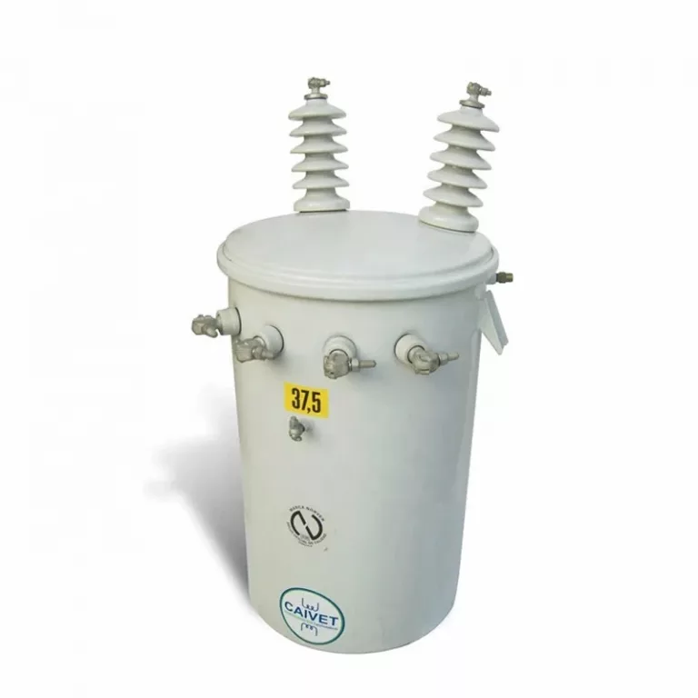
Daelim Belefic Single Phase Overhead Transformer is designed and produced normally for stepping utility distribution voltages (ranging from 2400 to 34500 volts) down to lower utilization voltages. Although some are used for stepping down to commercial and industrial voltages such as 277, 240/480, 2400, and 4800, most are used for stepping down to the single-phase transformer voltage of 120/240.
These transformers are also used for small substations, miscellaneous applications and can serve to step up voltages.
| Input Voltage | 37.5kv |
| Output Voltage | 380v,440V, 480V, 120-240V |
| Product name | single phase pole Mounted transformer |
| Input Voltage | 34.5kv |
| Warranty | 2 Years |
| Material | Copper |
| Color | Custom Made |
| Frequency | 50Hz/60Hz |
| MOQ | 6pcs |
| Capacity | 10KV |
| Standard | IEC ANSI IEEE |
| Certification | UL/IS09001/IS014001/RoHS/Reach |
| Input Voltage | 13.2v,34.5v |
| Output Voltage | 347v,600v |
| Input Voltage | 35kV, 34.5KV24.94KV13.8KV13.2KV11KV12.47KV |
| Output Voltage | 220V,380v,440V,480V,400V |
| Certification | ISO9001 |
| Material | Alumnium or copper winding |
| Cooling Method | ONAN ONAF OFAF |
| Warranty | 2 Years |
| Standard | IEC60076/AS/IEEE/ANSI/CSA |
| Core material | El Laminated Silicon Steel Sheet |
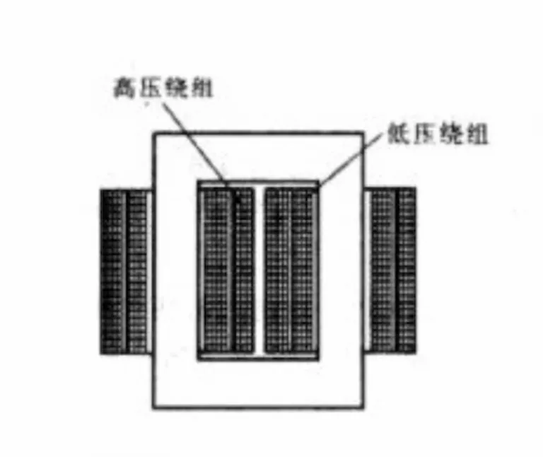
This is an electrical device that receives single-phase AC power as well as outputs single-phase AC. A single-phase transformer is utilized as a step-down transformer to reduce the home voltage to an acceptable value without frequency change. It consists of a magnetic iron core, functioning as a magnetic component, and a copper winding, which serves as an electrical part.
A 1 phase transformer is a kind of power transformer that uses a 1 phase alternating current. It indicates that the transformer banks on a voltage cycle that works in a phase of a unified process. They are usually utilized to decelerate long distances along with localized transmission currents within power levels. These are more appropriate for residential as well as light-commercial applications.
A single-phase transformer works according to Faraday’s principle of electromagnetic induction. Fundamentally, the mutual induction of two or more windings enables an electrical transformer to create transformation action. Based on Faraday’s law, the extent flux change of connection when it comes to time is correspondent to the established EMF in a coil.
Once the primary winding has been linked to a single-phase supply, an AC will begin passing through it. The primary AC current then generates an alternating flux in the core, joining the secondary winding. The varying flux will start triggering electricity into the secondary winding.
Both the primary winding and secondary winding is generally made up of insulated copper wire. Iron core needs to be separated, because of its substantial receptiveness. Industrial regulations and utility firms regulate the maximum voltage that applies to a single-phase transformer.

A single-phase transformer can connect into either series or parallel arrangements. A good example is the distribution transformer. It is generally coiled with secondary or windings with a low voltage that can be connected in parallel or series. The obtainability of primary voltages, including the fundamentals of the load, decides how a 1 transformer gets wired.
Essentially, transformers are considered AC devices with no fixed polarity, contrary to a DC source. However, they have comparative polarity markings that should be observed when joining them together in various arrangements.
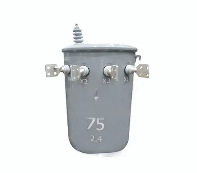
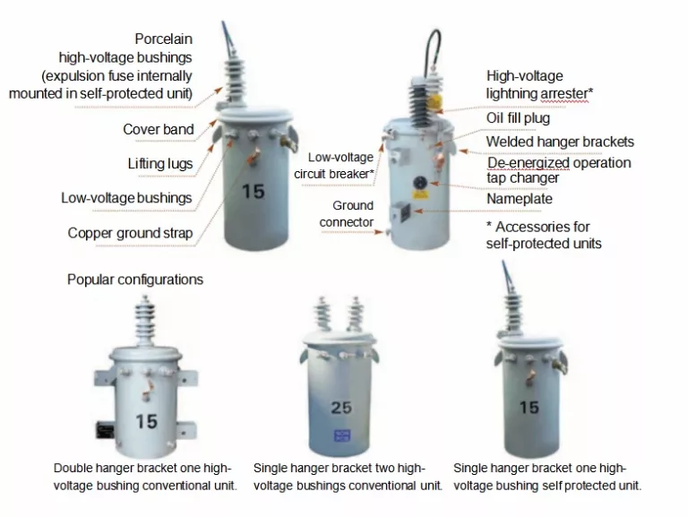
Normally, 1 transformer leads are built from the transformer’s steel casing straight from insulating bushings. All kinds of transformers have H and X terminals. H terminals usually have high voltage while X terminals have low voltage.
A single-phase transformer undergoes two important tests to ensure it will work properly to avoid disruption on the entire distribution system. These are the open-circuit test and the close circuit test. The test aims to ensure the proper distribution of electrical energy is made. The tests also determine the transformer’s equivalent circuit, voltage regulations, and efficiency.
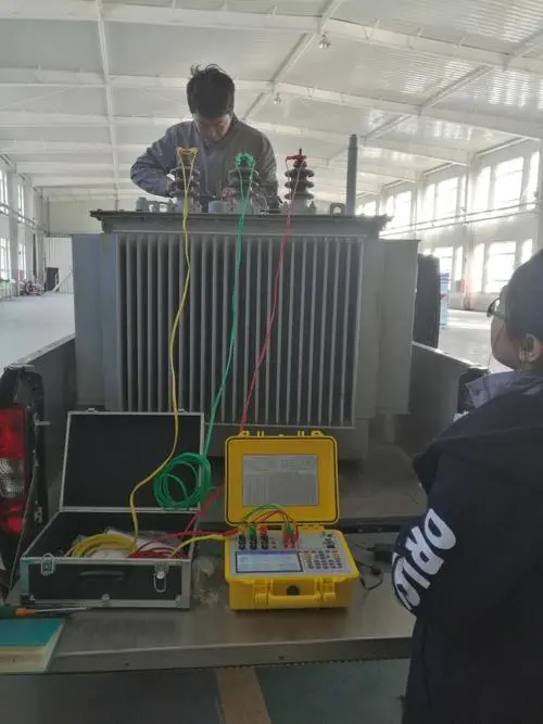
The short circuit or closed-circuit test determines copper losses in a single-phase transformer at full load. Likewise, it is used to acquire the range to maximize the transformer’s corresponding circuit. It indicates impedance, equivalent resistance, and leakage reactance.
The test on the single-phase transformer is conducted on the secondary or high voltage winding. The wattmeter, ammeter, and voltmeter are measuring instruments joined to the high voltage winding of the transformer. The primary winding is short-circuited using a thick strip or ammeter connected to its terminal.
The short circuit or closed-circuit test determines copper losses in a 1 transformer at full load. Likewise, it is used to acquire the range to maximize the transformer’s corresponding circuit. It indicates impedance, equivalent resistance, and leakage reactance.
The test on the single-phase transformer is conducted on the secondary or high voltage winding. The wattmeter, ammeter, and voltmeter are measuring instruments joined to the high voltage winding of the transformer. The primary winding is short-circuited using a thick strip or ammeter connected to its terminal.
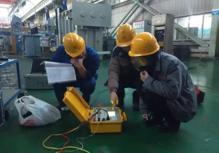
The low voltage source is connected throughout the transformer’s secondary winding. It’s because the full load current surges from the 1 transformer’s primary and secondary winding. The connected ammeter measures the full load current.
The power necessary for both open and short-circuit tests on a single-phase transformer is equivalent to the power loss resulting in the transformer. If the single-phase transformer doesn’t work correspondingly, the whole distribution system might get damaged and no electrical energy will be transferred. The electrical circuit may also get busted because of electrical damage, winding deformity, thermal change, and mechanical failures.
Other types of tests include:
This test verifies and confirms the transformer’s functional performance and is conducted in a production lot. It doesn’t include all tests but not the vacuum and temperature rise tests
Type tests verify if the single phase transformer is developed according to the customer’s expectations as well as design specifications. It includes testing the measurement of the transformer’s different specifications.
This test helps provide applicable information to the user and is performed during the operation and maintenance of the electrical device. It includes dielectric tests and measuring harmonics of the no-load current.
Pre-commissioning tests are conducted prior to the order or clearance of the single phase transformers at the site. It checks the installation process and analyzes the results.

This test enhances the performance and checks the transformer’s condition periodically if it satisfies customer requirements. Moreover, it helps determine the defects during the early stages through monitoring the transformer’s periodical performance.
Emergency tests are generally made at the site to check any issues or damages on the single phase transformer during the operation. For instance, high-temperature measurement even if the ventilators are working efficiently. This also involves windings resistance measurement and oil analysis used in cooling the transformer.
A single-phase transformer is considered a step-down transformer wherein the primary voltage is greater than its secondary voltage. It’s intended to decrease the voltage from the primary winding to the secondary wiring.
Below are the steps on how to wire a 1 phase transformer:
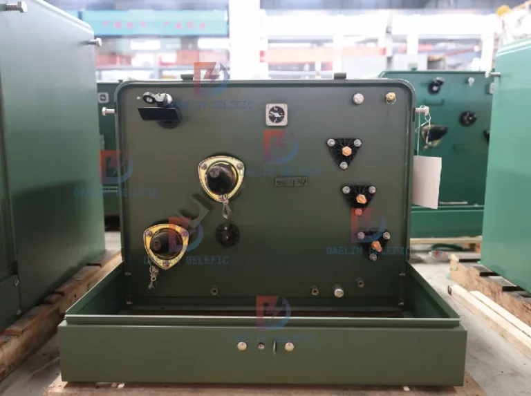
Step 1. Know the single-phase transformer’s schematic and rating to be fixed. Pull out the terminal connection box cover if the single phase transformer has high amperage. Additionally, remove the circuit’s electrical power and make sure that both sides of its protection are switched off.
Step 2. Identify which termination the single-phase transformer goes with. Terminations involve H1, H2, H3, and H4, indicating the high voltage side. At the same time, X1, X2, X3, and X4 signifies the transformer’s low voltage side. Even if the interconnection of the transformer differs according to the manufacturer and input voltage, the termination stays precise despite the transformer’s size.
Step 3. Connect the input wires and cut them based on the lug. It is also dependent on the amount of wire that slots in the crimping area.
Step 4. Join the outer insulating cover. This will allow the current to pass through the wire. Afterward, instill the wire lug across the stripped copper wire. Crimp the connection gadget to the wire permanently.
Step 5. Terminate the single-phase transformer’s high voltage side cautiously. Follow any procedures the manufacturer might have listed.
Step 6. Connect the low-voltage side of the single-phase transformer according to the manufacturer’s instructions. This includes the configuration that needs to be precisely followed. In small control transformers, there are only two terminals – X1 and X2. The X1 terminal is the line side, while the X2 terminal is the grounding side and low voltage.
Step 7. Terminate the control transformer for both X1 and X2. The X1 terminal goes directly to the control circuit after passing through a fuse, which is oftentimes developed for the circuit. The X2 terminal is joined to the control circuit’s neutral side and likewise utilized for grounding protection. Accordingly, the X2 terminal needs to be connected to the circuit’s grounding structure.
Step 8. Modify the single-phase transformer’s shield and any sections that impede current flow. Initialize the feeder power circuit to exert the high voltage to the transformer. Afterward, switch on the safety circuit on the low side.
Step 9. Check for voltage on the single-phase transformer. The objective is to make certain that the voltage is what’s exactly on the manufacturer’s list.
1 phase transformers are traditionally used in low voltage applications. This electrical device is largely adapted to minimize the voltage of a 220 volts supply. It can also be used in television sets for voltage regulation, stepping down localized power distribution, lowering the voltage on electronic devices, and more.
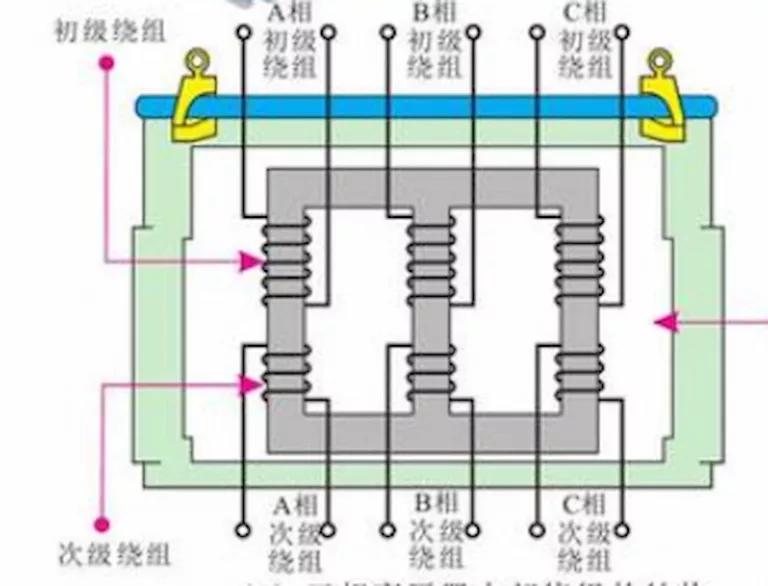
A 1 transformer treats power lines as an input source. It uses two windings (primary and secondary) for changing the voltage. A three-phase transformer, on the other hand, uses three windings (wye, mesh, and zigzag). These are coils joined in the precise sequence to match the incoming voltage and maintain accepted polarity and phasing.
A single phase transformer produces a lesser amount of electricity for supporting homes and non-industrial businesses. A three-phase transformer higher amount of energy sufficient enough that can support power grids and aircraft to name a few. It can also support other electronic loads higher than 1,000 watts.
The stability in power delivery is another noticeable difference between a single and a three-phase transformer. A 1 phase transformer can’t offer the same stability, unlike the three-phase transformer, which can deliver power at a stable and constant rate.
When it comes to efficiency, a three-phase transformer is better than a single-phase transformer. It can supply three-fold of power using less conductor material to deliver a sufficient amount of electrical power.
Additionally, a 1 phase transformer can’t start on its own and needs external devices. A three-phase transformer can start by itself without the need for external devices. At the same time, it can transpose the paths of two conductors.
When it comes to efficiency, a three-phase transformer is better than a 1 phase transformer. It can supply three-fold of power using less conductor material to deliver a sufficient amount of electrical power.
Additionally, a single phase transformer can’t start on its own and needs external devices. A three-phase transformer can start by itself without the need for external devices. At the same time, it can transpose the paths of two conductors.
A single phase transformer can only serve up to 230 volts. Contrastingly, it’s possible to maximize a three-phase transformer up to 415 volts.
Residential homes generally require a lower power supply, making the single phase transformer suitable to use. Less amount of power is needed to power mobile devices and small appliances. However, commercial and industrial firms necessitate heavier electronic load in which a three-phase transformer can provide.
Most home appliances need only a little amount of energy to function. This is why a majority of residential homes prefer a single phase transformer to accomplish it. A single-phase transformer can supply power to heaters, refrigerators, lights, televisions, and fans to function efficiently.
A single phase transformer’s design and operation are simple and ordinary. Its unit is compact and lightweight, producing a lower current when voltage transmission is high.
Because of the reduction in I2R, the current becomes low. This means that a single-phase transformer makes sure that the unit operates at an absolute degree with the increased efficient transmission.
A 1 phase transformer can be optimized with fractional or lower horsepower units up to 5 horsepower. It can be utilized to provide low voltages and high currents. Additionally, it can provide the desired output with up to 99% effectiveness without too much power loss.
A single-phase transformer can transmit electrical energy from one circuit to another circuit through mutual induction between the windings. It operates on the concept of electromagnetic induction. This electrical device contains both primary and secondary winding used to surge or subside the circuit’s voltage levels.
Testing a single-phase transformer has a key role in the excellent performance of the electrical device. It’s significant to conduct tests to avoid failures as it verifies specifications and proper functioning.
Table of Contents Selecting the right pad-mounted transformer requires careful consideration of several critical

The primary function of the pad mounted transformer is to serve as a critical distribution

A pad mounted transformer operates through electromagnetic induction, serving as a crucial distribution component that
When you need to find more than just existing transformers, Daelim’s Transformer Service Center can help you design and produce single-phase transformers that meet your unique needs.
We have our own factory and a professional team of engineers, which can design and modify application requirements that meet all your conditions.
Download Resource
ELECTRIC, WITH AN ENGE-- DAELIM BELEFIC
After filling in the contact information, you can download the PDF.