
How to Choose Pad Mounted Transformer?
Table of Contents Selecting the right pad-mounted transformer requires careful consideration of several critical
ELECTRIC, WITH AN EDGE
In this paper, we evaluate the insulation and thermal performance of ester fluid and mineral oil, and introduce the key technologies in the design, manufacturing and testing of such products, taking the offshore wind power transformer 6800kVA/35kV development as an example.
With the rapid development of offshore wind power, the need for high-capacity and long-distance transmission of wind power is becoming more and more urgent. Offshore wind power systems are limited by frequency conversion devices, installation space and harsh environments, so there are special requirements for wind turbines, converter equipment, wind power transformers and other transmission and substation equipment, as well as operation and maintenance.
Offshore wind power transformer is gradually becoming an important part of offshore wind power development, and is one of the key technologies for the development of offshore wind power to larger, deeper and more distant waters. However, the lack of standards and operational data makes many issues and methods in the design of offshore wind power transformers still in the research and development phase, and the application of related technologies has yet to be verified.
The operation of an offshore wind power transformer is different from that of a conventional wind power transformer; the main differences between offshore wind power and onshore wind power are high utilization hours and a smoother power generation process, particularly high maintenance and repair costs, strict volume and weight constraints, and strong mechanical vibrations. The design requirements are environmental protection, fire protection; extreme reliability, very low failure rate, high overload capacity; compact structure to adapt to the doorway; easy installation, light weight; maintenance-free or less maintenance and low maintenance costs.
In this paper I present the development and design of the largest single capacity offshore wind power transformer 6 800kVA/35kV, 3 wind power transformers with Haliade 150-6MW offshore wind turbine.
A wind transformer is a step-up wind transformer because offshore wind turbines use step-up wind transformers to connect the turbine to the grid, so the wind transformer is a step-up wind transformer, which is installed in the tower and requires an oil-immersed wind transformer.
In the electrical design of an offshore wind transformer, attention needs to be paid firstly to very fast transient overvoltages (VFTO), harmonics and non-sinusoidal loads and load fluctuations; secondly, in the mechanical design, careful consideration needs to be given to mechanical vibrations, excitation inrush, low voltage ride-through and cooling.
Finally, these various variations required a review of the raw materials used and an evaluation of ester versus mineral oils in terms of insulation and thermal performance, including key modifications in design, manufacturing and testing to ensure superior performance and longer life.
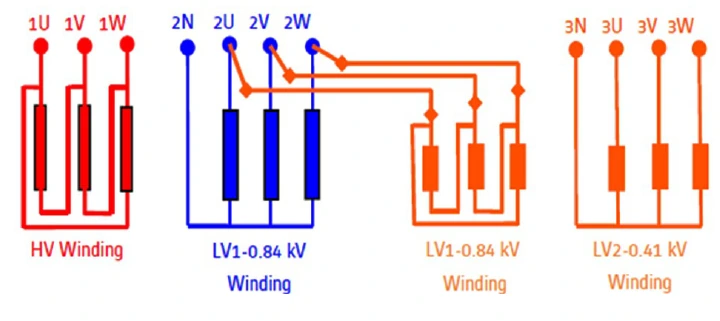
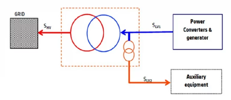
The winding arrangement of the main wind power transformer and auxiliary wind power transformer is shown in Figure 1, and the power transfer is shown in Figure 2. The main transformer LV1-HV body and the auxiliary transformer LV1- LV2 body share a common oil tank, where the main transformer LV1 is connected to the auxiliary transformer LV1 via a fuse, and the auxiliary transformer supplies power to the wind turbine auxiliary equipment. The wind turbine transformer is cooled by primary and secondary circuits, with the primary circuit being the K-level coolant to the water exchanger for heat exchange and the secondary circuit being the water to the air cooler for heat exchange.
Ambient temperature: -10 ~ +45℃, humidity 90%, anti-corrosion protection C4
Dimension: ≤3 500mm×1 100mm×3 250mm (L×W×H)
Total weight: <12t
Vibration: >10Hz (first-order characteristic frequency)
Number of phases: three phases
Frequency: 50Hz, variation range ±5%
Winding material: copper
Rated capacity: 6 800kVA, 200kVA
Coupling group: Dyn11 (6 800kVA), Dyn11 (200kVA)
Rated voltage: HV/LV1: 35±2×2.5%/0.84kV, range of variation ±10%
LV1/LV2:0.84/0.41kV,variation range±10%
Harmonic voltage: DC component can be ignored, the highest voltage harmonic frequency 2kHz ~5kHz, total harmonics <5%, LV side harmonic peak voltage <2kV
Harmonic current: total harmonics <5%
Insulation level: LI200AC85/LI40AC10 (6 800kVA).
LI40AC10/AC3 (200kVA)
Short-circuit impedance: 9.5% (6800kVA), short-circuit capacity 1000MVA
5% (200kVA)
No-load loss: 6.8kW
Load loss: 60.5kW
Temperature rise: top ester liquid ≤ 80K, the average temperature rise of windings ≤ 110K
Cooling medium: MIDEL 7131 synthetic ester liquid
Cooling method: KFWF forced synthetic ester circulating water cooling
Oil storage cabinet: capsule type oil storage cabinet and maintenance-free moisture absorber
Excitation inrush current: peak <7.5×Ir (Ir is the rated current of high-voltage winding)
Partial discharge: <50pC (1.2×Ur, Ur is the rated voltage of high-voltage winding)
This section focuses on the key considerations for electrical design, such as repetitive high frequency transient overvoltage/undervoltage in the 0~1kHz range; harmonics and load fluctuations.
The electrical design takes into account a variety of different overvoltages, the frequency distinctions of which are shown in Table 1.
Differentiation of frequency ranges
Marking | Typical frequency range | Overvoltage |
Low frequency oscillation | 0.1Hz~3kHz | Short time overvoltage |
Low frequency pulses | 50/60Hz~20kHz | Switching overvoltage |
High frequency pulse | 10kHz~3MHz | Lightning overvoltage |
Very high frequency pulses | 100kHz~50MHz | Very fast transient overvoltage (VFTO) |
In Table 1, apart from lightning shocks and industrial frequency overvoltages, the greatest risk of operational failure of the wind power transformer is the very fast transient overvoltage (VFTO), with a typical frequency of 100 kHz to 50 MHz.
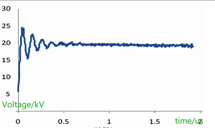
A typical VFTO waveform example is shown in Figure 3, with a wavefront time of only 0.044 µs, a short wavefront time that seriously affects the internal insulation withstand voltage of the wind power transformer. In Brazil and North America alone, 154 transformers have been subjected to insulation breakdown due to exceptionally fast transient overvoltages.
The offshore wind power transformer is installed in the tower or nacelle, allowing the wind turbine and transformer to be closely connected, reducing the cable length and connecting the wind power transformer high voltage cable to the vacuum breaker.
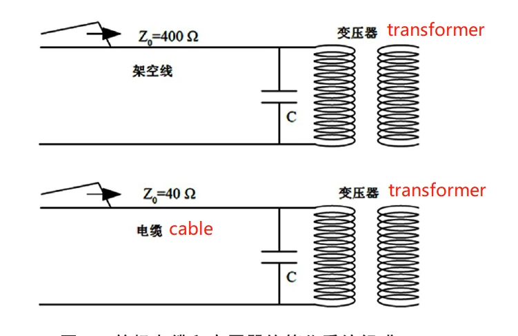
Single-phase cables and transformers are simplified in Figure 4, the cable and overhead line wave distribution parameters are clearly different, because the cable conductor spacing is much smaller than the overhead line, so the capacitance to ground cable is much larger, while the same length of cable than the overhead line reactance is much smaller due to increased mutual inductance between the wires. Overhead lines exist between the line capacitance, while the cable is individually shielded without interline capacitance.
Different wind power transformer winding structure has a different inherent frequency, vacuum circuit breakers have extremely fast opening time.
High- and low-voltage side of the circuit breaker breaking operation produces a very fast transient overvoltage, the duration of only a few milliseconds, the wavefront time of a few nanoseconds to tens of nanoseconds, high-voltage circuit breaker opening process, a very fast transient overvoltage wavefront time is about 50 times shorter than the full wave of lightning shock 1.2μs.
The high frequency voltage ratio is determined by the stray capacitance and inductance together, for example, 6 800kVA/35kV wind turbine, the voltage ratio is about 0.015 at 50Hz, and about 1.5 at 2MHz, then the 2MHz sine wave will produce about 100 times overvoltage.
The oil-paper insulation system, which shortens the wavefront rise time, has a significantly lower turn-to-turn withstand voltage. The volt-second characteristics of oil under uniform electric field are shown in Fig. 5. Compared with the standard lightning surge voltage wavefront time of 1.2 μs, the breakdown voltage is reduced by about 12% for a wavefront time of 0.7 μs and by 35%-40% for a wavefront time of 0.044 μs for an extra fast transient overvoltage.
Extra fast transient overvoltage is transmitted to the transformer in wind turbine through the cable. If the main frequency of the extra fast transient overvoltage caused by the switching operation on the low voltage side and high voltage side is the same as the inherent frequency of the winding, it may generate electrical resonance and produce overvoltage of many times the original voltage level.
In an offshore wind farm with multiple single-phase ground faults, the oscillation overvoltage of the disconnected circuit breaker reaches 7 times the normal operating voltage (the maximum overvoltage of a conventional power transformer in wind turbine is about 4.5 times), which exceeds the maximum overvoltage of a conventional transformer in wind turbine, and the overvoltage may lead to inter-turn or interlayer breakdown due to the inter-turn field strength exceeding the insulation withstand strength.
Offshore wind power transformer consider extra fast transient overvoltage, one method is to use components such as lightning arrester, capacitor or resistor for buffer protection.
Another method is to change the winding structure form, because the winding selection layer type, pie type or multi-segment layer type has different inherent frequency.
The first-order intrinsic frequency of layer winding is about 1MHz, and it is not advisable to use 50m long cables for high voltage to avoid resonance.
The first-order intrinsic frequency of pie winding is about 70kHz, while the high order intrinsic frequency is associated with 100kHz~500kHz. Considering the avoidance of resonance, it is not advisable to use more than 100m long cable for high voltage; the first-order intrinsic frequency of multi-stage layer winding is about 10kHz~1MHz or more than 1MHz.
Focusing on the consideration of extra fast transient overvoltage, 6 800kVA/35kVtransformer in wind turbine high-voltage winding should choose layer winding or multi-segment layer winding, and its inter-turn and inter-layer oscillation overvoltage should be designed according to 7 times of normal working voltage; 2 layers of insulation should be added at the beginning and end of high-voltage, and the main insulation should be formed into corner rings, and the insulation forming parts should be added at the high-voltage outlet.
The wave process calculation software can be used to calculate the inherent frequency. GB1094.16 specifies the electric resonance frequency measurement method, through the low-voltage short circuit and low-voltage open circuit two frequency response overlap is the electric resonance frequency.
The wind power transformer recommends considering extra fast transient overvoltage according to the wind farm system, and appropriately improve the insulation level, the standard to be improved; the test must focus on: higher surge voltage, shorter wave head time, higher cut-off surge voltage and longer switching operation wave, while the non-test winding terminals are not grounded.
Additional nonlinear loads such as circuit breakers, rotating motors and variable frequency drives in wind power systems generate harmonics, and these accumulated harmonics repeat over and over, boosting voltage and current peaks when they are not fundamental frequencies. Wind turbines, just like conventional generators, produce generator distortion and generate harmonics.
In addition to these harmonics generated by the generator, there are also destructive harmonics generated by the PWM voltage source inverter. Wind power transformers are often subject to non-sinusoidal load currents and harmonics, and IEC 60076-16 has pointed out this risk and stipulates that the customer should provide a harmonic spectrum.
The hazard of harmonics is the increase of eddy currents and stray losses in the transformer in wind turbine. The eddy currents and circulating currents in the winding conductors cause additional heating and must be treated with additional cooling to avoid premature insulation deterioration and local overheating failures in the transformer in wind turbine.
The presence of harmonic currents will cause harmonic voltage drops in the line impedance. Harmonic voltage will increase transformer in wind turbine flux density, no-load loss, no-load current, noise and core temperature rise.
Considering the frequency and voltage variations, the 6 800kVA/35kV wind turbine design considers 15% overvoltage, and the silicon steel sheet is selected as 30RK105 with a minimum saturation magnetic density of 1.9T and an operating magnetic density of about 1.65T.
The loss and temperature rise at 5% of the total harmonic current; finally, the high frequency component is also considered to prevent local overheating of the metal structural parts.
In wind power and photovoltaic systems, inverters have the highest failure rate. The harmonics generated by PWM voltage source inverters (switching frequency approx. 4 kHz) contain high frequency components (frequencies 350 Hz, 450 Hz, up to 2 kHz).
If it passes through the transformer in wind turbine, it may affect the transformer in wind turbine and other devices on the grid, e.g. the protection equipment may see this as a fault and try to cut off the turbine.
The placement of a grounded electrostatic screen between the primary and secondary windings of the wind power transformer acts as a filter and prevents the transfer of dangerous harmonic high frequency components to the high voltage side.
As long as the use of PWM voltage source inverters, transformer in wind turbine high and low voltage winding must be arranged between the ground electrostatic screen, such as excitation transformer in wind turbine, photovoltaic transformer in wind turbine and wind power transformer, etc., the main four functions are as follows.
① suppress overvoltage. The electrostatic screen makes the parasitic capacitance between the primary and secondary windings close to zero, inhibiting the transmission of overvoltage.
② suppress the transmission of high harmonics. Electrostatic screen to inhibit the rectifier circuit generated by the high harmonics to the network side; ② inhibit the transfer of high harmonics.
③Reduce electrostatic noise. Electrostatic screen set up between high and low voltage windings is conducive to reducing the electrostatic noise caused by harmonics; ③ reduce electrostatic noise.
④ Prevent the protection equipment from misoperation. The grounding screen line also needs to withstand 1kA, 1s short-circuit current.
Variations in wind power mean that the turbine is operated under a constantly changing load and the transformer in the wind turbine is subjected to frequent daily alternating hot and cold cycles.
In contrast to conventional power transformer in wind turbines that operate daily under a single load, the wind turbine can cycle from very low to very high loads many times a day under momentary local wind.
This cycling triggers repetitive thermal and mechanical stresses in the windings, body and clamped structural components. The repetitive thermal stress cycles cause air (or nitrogen) to be absorbed by the hot oil and then released as the oil cools, forming tiny bubbles in the oil that transfer to the insulation components to form partial discharges or hot spots that can lead to insulation loss and deterioration. Continuous thermal cycling, likewise, may accelerate the triggering of aging of internal and external electrical connection components.
The cumulative effect of frequent low to high load cycles exposes the offshore wind power transformer to a higher risk of insulation fatigue failure.
The mechanical properties, flexibility, elasticity and impregnability of the interlayer insulation paper and end insulation must be taken into account in the design of the offshore wind power transformer 6 800kVA/35kV.
For the Oil Immersed wind transformer, the liquid at the point of partial discharge can be replaced and the insulation strength restored at any time by injection of new insulating liquid.
Compared to the dry transformer in wind turbine, the heat resistance of the high temperature insulating material and the electrical properties of the K ester fluid make the insulation of the liquid immersion transformer in wind turbine less sensitive to the high electrical stresses imposed by frequent switching on and off, transfer overvoltages and transient surges.
For easy access and maintenance, to ensure strength and to prevent damage to the wind turbine tower, the transformer in wind turbine must be able to pass through the doorway.
6800kVA/35kV transformer in wind turbine external dimensions ≤ 3 500mm×1 100mm×3 250mm (length×width×height), total weight <12t.
6800kVA/35kV wind power transformer doorway size and total weight need to be carefully considered.
In addition to short-circuit impedance and loss and other performance parameters requirements, but also to meet the size and total weight requirements, in the design of the special preparation of electromagnetic optimization design program repeated calculations, and finally converge on the optimal design scheme, winding more thin and high type; in order to meet the total weight requirements, such as clamping parts using high-density laminated wood.
In addition to the special fast transient over voltage electrical resonance, the structure should also focus on mechanical resonance, 6 800kVA/35kV transformer in wind turbine vibration first-order characteristic frequency > 10Hz. A large number of cases show that the transformer in wind turbine installed in the nacelle or tower is affected by the vibration generated by the fan. When the wind load strikes the turbine blades, it will cause the transformer in wind turbine to vibrate violently.
To mitigate the effects of vibration, the use of Oil Immersed wind transformer can be properly improved (insulation liquid is equivalent to damping), liquid immersion than epoxy cast transformer can more effectively withstand the vibration displacement and mechanical resonance stresses generated at resonant frequencies of 5Hz ~ 250Hz.
The 6 800kVA/35kV wind power transformer was designed using SolidWorks software and vibration simulations were done specifically.
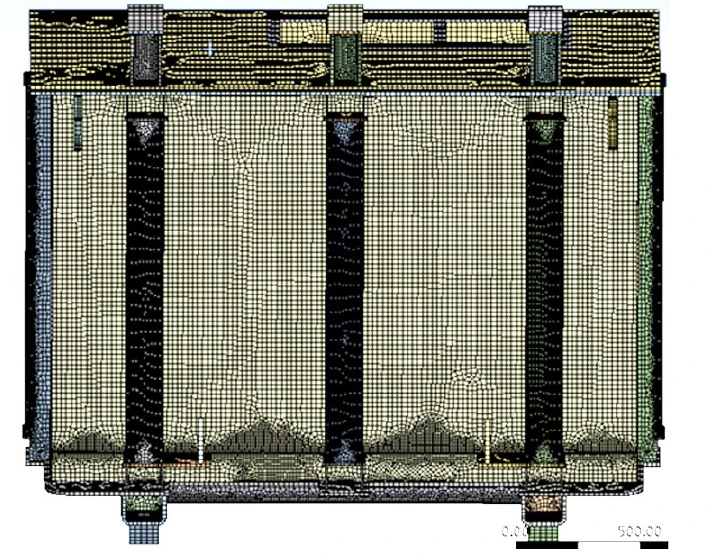
The vibration simulation mesh model is shown in Fig. 6. The thin-walled parts of the tank are divided into shell cells, while the reinforcement plate, fixed parts and other parts whose thickness and cross-section do not differ much are divided into solid meshes. The material of the tank and reinforcement plate is steel, and the modulus of elasticity is set to 2.1e5MPa, Poisson’s ratio is 0.3, and the density is 7,850kg/m3.
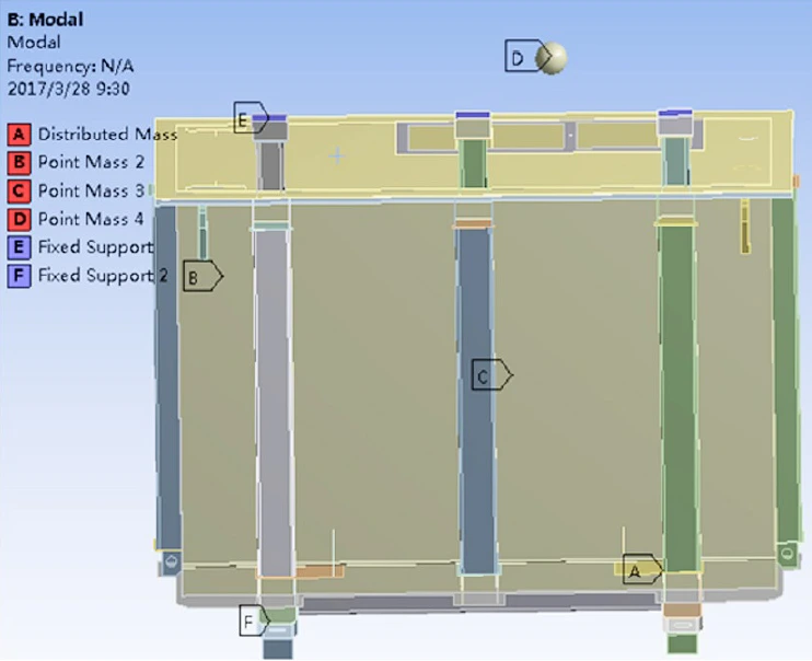
The contact and constraint are shown in Fig. 7. The contact between all parts is set to be bound contact during the simulation. The oil tank of the 6 800kVA/35kV transformer is reinforced both horizontally and vertically as a way to reduce vibration.
In addition, structural members are reinforced inside the transformer to hold it in place so that the transformer body is not displaced in any direction. The model is positioned by adding supporting mounting plates, and fixed constraints are added to the two mounting plates at the bottom of the tank and the three mounting plates at the cover.
The first-order inherent frequency of the 6 800kVA/35kV transformer simulation (see Figure 8) is 28.885Hz>10Hz, which meets the requirements.
Figure 9 tests the inherent frequency of the 6 800kVA/35kV transformer by lifting the transformer with a flexible rope and leaving it in a free state.
Knockdown test method using shock response function test, in front of the transformer tank, back, left and right four sides, respectively, after the test data analysis, the test 6 800kVA/35kV transformer first-order inherent frequency of 19Hz>10Hz, to meet the requirements.
In addition, winding coupling or lead joint reliability and bolt loosening prevention should be carefully considered in the mechanical design. If the winding coupling or lead joints are not operated properly, vibration during transportation, short circuit and operation may lead to fatigue failure.
The selection of the lead cable and the insulation distance from the lead cable to the box wall are determined according to the insulation level, and the lead clamping must be reliable. Particular consideration needs to be given to the transfer of vibration stress to the connection terminals, such as bushings, which must be effectively supported.
The generator step-up function is important for the wind power transformer and is designed to meet the requirements in accordance with the generator transformer. As soon as the wind turbine starts to generate electricity, the power flows to the load via the low voltage side of the wind turbine.
The wind power transformer no-load losses and no-load currents are small, which leads to long excitation inrush times and can lead to false protection. In the design, the excitation inrush current and the inrush current should be considered for the related wind power transformer body structural components.
The 6 800kVA/35kV transformer requires an excitation inrush peak value of <7.5Ir.
The simulation software calculates the peak excitation inrush current as 609.11A and the rated current Ir=112.17A, 609.11/112.17≈5.4<7.5, which meets the technical requirements.
Low voltage ride-through capability of wind power transformer to put forward higher electrical, magnetic, thermal and mechanical stress requirements, force transformer in the role of overcurrent caused by external short circuit should be no damage, transformer short-circuit dynamic stability time of 0.25s; wind power transformer and network voltage drop of 20%, the required ride-through time of 0.625s>0.25s, wind power transformer requires excellent ability to withstand short circuit.
Considering the short-circuit mechanical strength requirements of 6 800kVA/35kV wind power transformer, copper foil is selected for the low-voltage winding and high-temperature 200-grade semi-hard enameled flat wire is selected for the high-voltage winding; the winding is round instead of oval.
In the design, the short-circuit force should be small and the protection force should be large; in the production, ensure tight winding, tight sleeve and tight compression. Due to the limitation of space, the detailed measures to improve the mechanical strength of the short circuit will not be repeated.
The process should focus on whether the interlayer insulation dot paper is effectively cured, heat-resistant paper curing heating time should be extended appropriately.
The life of the transformer is determined by the hot spot temperature rise of the winding, hot spot temperature rise increases by 6°C ~ 7°C, the mechanical life of cellulose insulation is halved. Under typical operating conditions (including overload, high temperatures and low cooling efficiency), the superior thermal properties of high temperature insulation materials with high temperature insulating fluids effectively prevent thermal aging.
A compact, naturally cooled KNAN transformer is the preferred choice. When the turbine power reaches 4 MW or more, a separate cooler becomes important, as the transformer losses generate heat that does not allow direct heat dissipation into the tower or nacelle.
The cooling of the 6800kVA/35kV transformer was achieved by means of a KFWF.
The design is firstly based on IEC60076.2 temperature rise standard to do temperature rise correction: ambient temperature -10℃~+45℃, average ambient temperature rise correction Kav=27.5-20=7.5, maximum ambient temperature rise correction Kmax=45-40=5, then the top ester liquid temperature rise requirement Δθ0=80-5=75K, average winding temperature rise requirement Δθw=110-7.5=102.5K; secondly, we should consider the effect of harmonic current.
Finally, the influence of external solar radiation on the temperature rise should be considered, such as the reference standard IEC60721-4-4, the influence of direct sunlight is 1 120W/m2, if the calculation does not take into account, the temperature rise will increase by 15℃.
To reduce the hot spot temperature rise, KDWF is preferred, but the structure becomes complicated by increasing the guiding path of the body.
By increasing the winding conductor cross-sectional area, reduce eddy current loss and stray loss to reduce the load loss, compared with copper wire, aluminum wire is a more economical choice, aluminum winding due to the difference in current density, aluminum winding wind power transformer form factor will be appropriate to increase, need to weigh the size of the doorway and the total weight limit.
The fierce competition in the transformer industry and issues such as environmental protection, fire prevention and carbon emission reduction have pushed the transformer industry to use environmentally friendly K-grade insulating fluid, which is divided into two types: natural ester and synthetic ester.
In this paper, I compare some of the key properties of mineral oil and ester fluid, which cover some important contents in order to provide guidance for the design of an in-depth understanding of the advantages and disadvantages of ester fluid, environmental protection and fire prevention and other properties will not be repeated.
For transformer designers, the ability of the insulating fluid to withstand transient overvoltages is very important. Transient overvoltages can be either positive or negative polarity. In a uniform electric field, positive and negative polarity have no effect on breakdown voltage.
Although the positive and negative polarity has little or no effect on the breakdown voltage of the liquid in a uniform field, but the liquid in an inhomogeneous electric field has a great impact.
In the cardboard maximum not more than 100mm gap, with the needle – plate method of distribution (extreme uneven field strength), ester liquid lightning breakdown voltage value is close to 65% in mineral oil, gap of 100mm ~ 1 000mm for 40%. When the field strength is uniformly distributed, the lightning breakdown voltage is almost the same for ester fluid and mineral oil.
6800kVA/35kV transformer insulation design, mineral oil increase 30% for insulation design, uniform field strength distribution and consider more cardboard separation and avoid large oil gaps, key parts including lead to tank wall, etc..
High-voltage winding to the core and to ground distance and phase distance should be increased by 30% compared with mineral oil transformers. In addition, the spacing between switch terminals and the insulation distance inside the cable plugging head should be enlarged appropriately.
Partial discharge is a quality control test that can reflect some problems in design, material and production process. Partial discharge in ester fluid occurs at a lower voltage than mineral oil.
Three offshore wind power transformer 6 800kVA/35kV, the background noise during the test is 20pC, and the partial discharge under 1.2Ur is 30pC~40pC, less than 50pC.
If the test of high-voltage cable head and other poor grounding, will also cause 200pC ~ 1 000pC local discharge; if the static discharge time is not enough, the starting partial discharge voltage will be very low, in 1.2Ur partial discharge can reach 500pC ~ 2 000pC, which may lead to local insulation damage in the transformer.
Material compatibility is critical in the design of Oil Immersed wind transformer. For compatibility, variations in acid value, dielectric loss, viscosity and surface tension are the main considerations.
In general, the materials used to produce standard mineral oil transformers are compatible with ester fluids. Materials are listed by type, but there may be several different proprietary formulations within a particular type.
The reaction of different formulations of materials to ester fluids may vary depending on the small number of additives, and this is especially true for elastomers and polymers, such as conductor varnish, case wall paint and secondary cables, and ester fluid compatibility.
The sealing materials for the offshore wind power transformer 6 800kVA/35kV were all selected from fluoroelastomer (or fluorosilicone rubber) after a series of compatibility tests.
It is important to note that the water content limits for mineral oils are not directly applicable to ester fluids because they are hygroscopic and can bind more water and still maintain allowable dielectric strength values.
However, the effect of water content on dielectric strength, as a function of saturation, is the same for ester fluids and mineral oils.
The water content that does not affect the dielectric strength of the Oil Immersed wind transformer after commissioning is approximately 400 ppm or less.
In order to remove moisture from the insulating parts and increase the impregnation rate, the transformer insulating fluid is heated before vacuum filtering.
Excessive heating has a negative effect on the dielectric loss factor of the insulating fluid. Ester fluids have a lower thermal limit to initiate phase change than mineral oil.
During processing, the ester fluid has a longer contact time with the heating element compared to mineral oil due to its higher viscosity.
A possible solution is to limit the maximum power density or heating density, preferably by using plate heaters (increased heated area and reduced concentrated heating).
When the critical heating temperature is exceeded, the decomposition and carbonization of molecules and polar particles may occur due to local overheating, which can be clearly seen experimentally as a layer of liquid adhering to the heater surface, which is not seen in mineral oils.
The higher viscosity of the ester fluid has a greater influence on the turbulence of the transformer insulating fluid, the impregnation time of the solid insulation, the resting time before testability and the overall thermal characteristics.
Due to the higher density and viscosity of the ester fluid, the solid insulation takes longer to impregnate at a given temperature. Due to the hygroscopic nature, moisture tends to remain in the ester solution more than in the mineral oil, which increases the lifetime of the insulation system.
Insulating varnishes, Nomex and glass fibers are composite materials and are not fully impregnated with the insulating solution.
Paper, cardboard and laminated wood are all based on natural materials and can be fully impregnated with the insulating fluid.
Thicker laminated wood end rings and pressure plates, etc. slotted and perforated should be increased appropriately in order to improve the ester impregnation performance.
Insulation impregnation time, at the same temperature, ester liquid cellulose impregnation time is twice as long as mineral oil.
The temperature requirements for transformer oil filling, with ester fluids requiring higher fluid temperatures.
The resting time before insulation test is almost twice as long as mineral oil at the same temperature for ester fluid. The processing time of ester fluid is much longer than mineral oil.
6 800kVA/35kV transformer insulating fluid using Midel7131 synthetic ester, the oil temperature for vacuum oil injection in the treatment process is 80℃~90℃, and the pressure is set at 0.5mbar~4mbar.
The hot oil circulation time in the whole transformer system needs to reach 108h.
After the hot oil circulation, it needs to be static, and the static time is at least 96h.
Control of granularity requires replacement of filter elements 1 level 10μ and 2 level 1μ. To shorten the insulation impregnation time, positive pressure (e.g. 3atm~4atm) can be used.
Miscibility is a continuous property that is mixed in all ratios and forms a homogeneous solution.
The ester solution can be 100% mixed with mineral oil at all ratios and a small amount of mineral oil will not affect the performance of the ester solution. A small amount of mineral oil will not affect the performance of the ester fluid. If more than 7% of mineral oil is present, the ignition point will be lowered to below 300°C, which is the minimum ignition point for Class K insulating fluid.
The new ester fluid has a higher dielectric loss compared to mineral oil. Transformer dielectric loss test results show that ester fluids have higher dielectric loss than mineral oil under normal operating conditions.
Ester fluids have slightly more polar molecules in their chemical composition than mineral oils, which results in higher dielectric losses than mineral oils.
Ester liquids have a lower resistivity than normal mineral oils. A comparison of the insulation resistance of the two transformers is shown in Table 11, which shows that the insulation resistance of mineral oil is about 10 times higher than that of MIDEL7131 ester fluid.
Due to the low resistivity of the ester fluid, more charge transfer and higher electrostatic charges are generated, and forced oil circulation is also required to control the oil flow rate to avoid charged oil flow.
Chromatographic stray gas is the gas formed when insulating oil is heated at relatively low temperatures (90°C~200°C). Table 12 gives the applicability analysis of ester fluid and mineral oil under different failure conditions. When the ester fluid is in relatively low temperature range (80℃~250℃), it will volatilize a lot of stray gases, such as ethane and hydrogen gas will be generated if the oil temperature reaches 55℃ or more.
Stray gas generation can be observed for a period of time (weeks to months) after transformer operation. At the same voltage level, ester fluid generates more gases during partial discharge than mineral oil. These are dominated by hydrogen and ethane, and subsequent operating oil chromatography data are to be collected.
The offshore wind power transformer requires extreme reliability with strict size and gross weight limitations, unlike standard power transformers, and must be designed to optimize performance, especially electrical and mechanical resonance, by considering the interplay of different electrical properties, mechanical properties and material requirements on operating conditions.
The evaluation of ester fluids versus existing mineral oil insulating fluids in terms of lightning shock, partial discharge, material compatibility and thermal performance also included key modifications in design, manufacturing and test operation to ensure excellent performance and longer life.
In order to reduce asset risk and discuss key characteristics in comparison, ester-based high temperature insulation systems are the preferred choice for offshore wind power transformers.
The overall design and process of the ester offshore wind power transformer needs to be updated, and standards such as operation and maintenance need to be improved.
To reduce operation and maintenance costs, it is recommended that the transformer be installed with some online monitoring equipment, such as oil chromatography, fiber optic temperature measurement, transient overvoltage and UHF partial discharge.
Download Resource
Table of Contents Selecting the right pad-mounted transformer requires careful consideration of several critical

The primary function of the pad mounted transformer is to serve as a critical distribution

A pad mounted transformer operates through electromagnetic induction, serving as a crucial distribution component that
After filling in the contact information, you can download the PDF.