
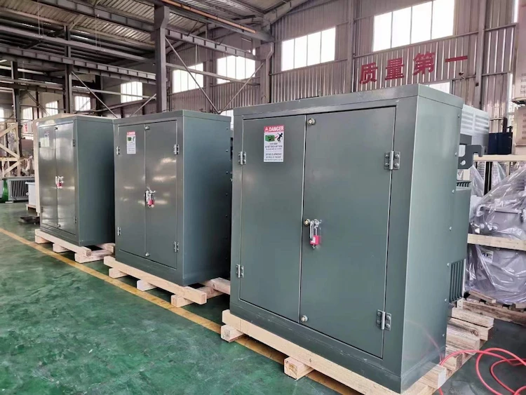
How to Choose Pad Mounted Transformer?
Table of Contents Selecting the right pad-mounted transformer requires careful consideration of several critical
ELECTRIC, WITH AN EDGE
The configuration of the solar storage nec’s reactive power compensation is essential for its stable operation. The reactive power losses in the box transformers, collector lines, step-up transformers and feeder lines of the PV and storage installations are calculated in relation to the system configuration of the solar and storage nec.
Taking the actual solar and storage nec project as an example, the calculation of reactive power compensation capacity is carried out in conjunction with the actual configuration of the project and other circumstances, and the issues that need special attention in the calculation of the capacity of reactive power compensation devices in the solar and storage nec booster station are proposed, as well as the specific requirements for reactive power compensation devices.
Actively responding to climate change and striving to build a clean, low-carbon, safe and efficient energy system is a major decision and deployment made by the Party Central Committee and the State Council. In order to implement the goal of carbon peaking and carbon neutrality, the development of new energy storage is taken as an important step to enhance the regulation capacity of power systems and support the construction of new power systems.
At present, in order to enhance the capacity of renewable energy, all provinces and cities have proposed to equip new market-based grid-connected renewable energy projects with a certain capacity of energy storage devices.
The construction of solar and storage nec projects is not only a concrete way to achieve the “double carbon” goal, but also to improve the consumption capacity of photovoltaic. Solar and storage nec projects have a negative impact on the power quality and the safety and stability of the grid. The reactive power compensation of the solar and storage nec is essential for the stable operation of the power station.
During normal operation of a photovoltaic power station, the electricity generated is connected to the grid through the box transformers, collector lines, step-up main transformers and delivery lines of the photovoltaic sub-matrix, so there are reactive power losses in the transformers and lines of the photovoltaic power station at all levels, and there are reactive power losses in the box transformers and collector lines of the energy storage device.
The reactive power compensation device should be able to compensate the reactive power losses of the relevant equipment, achieve dynamic continuous regulation, have the ability to control and network voltage, and the regulation speed should be able to meet the needs of the grid voltage regulation. Therefore, solar and storage nec need to install centralised reactive power compensation devices for compensation.
In this paper, according to the reactive power loss composition of solar and storage nec, reactive power compensation calculation is carried out, and its reactive power loss analysis and calculation are combined with the actual engineering situation, and the conclusion of reactive power compensation capacity configuration is drawn.
Daelim Belefic’s transformers are designed for maximum efficiency and reliability in solar storage plants. With a focus on safety and compliance with international standards, they are an excellent choice for customers looking for high-quality, durable transformers.
If you’re looking for a reliable and efficient transformer for your solar storage plant, Daelim Belefic has you covered. With a commitment to safety and compliance with international standards, their transformers are built to last and deliver top performance.
Choosing the right transformer for your solar storage plant is critical, and Daelim Belefic offers some of the best in the industry. With a focus on quality and safety, their transformers are designed to meet the unique needs of solar energy applications and deliver consistent performance over time.
The solar and storage nec system mainly consists of a photovoltaic power generation section and an energy storage section.
The solar and storage nec system consists of a series of photovoltaic modules, converters, inverters and voltage boosters, etc. The solar and storage nec system consists of an energy storage battery system, transformers, collector lines, electrical secondary equipment and auxiliary equipment.
The photovoltaic power generation section consists of several photovoltaic modules and centralised inverters connected in series and parallel to form several photovoltaic power generation units. Each photovoltaic power generation unit is equipped with a 35kV box-type transformer to step up the voltage to 35kV, which is connected to the 35kV side of the photovoltaic field boosting station through several sets of collector lines.
The energy storage section consists of a number of energy storage batteries and energy storage converters forming energy storage nodes, every 4 energy storage nodes forming 1 energy storage unit, each energy storage unit is equipped with a box-type transformer stepped up to 35kV and connected to the 35kV side of the PV field booster station via a number of sets of collector lines. The low voltage side of the main transformer of the PV field booster station is 35kV.
The step-up method is determined according to the installed capacity of the solar and storage nec project and the grid-connected voltage level. If the grid-connected voltage level is 35kV, only box-type transformers are needed in the field to step up the voltage and connect to the grid.
If the grid-connected voltage level is 110k V or 220kV, the box-type transformer and the main transformer will be stepped up separately. The inverter outlet voltage will be stepped up to 35kV via the box-type transformer and then connected to the main transformer via multiple 35k V collector lines to be stepped up to 110k V/220k V. The inverter will then be connected to the grid using the feeder lines.
The reactive power loss of solar and storage nec mainly comes from the reactive power loss of PV box transformers, PV collector lines, main transformers, delivery lines, storage box transformers, storage collector lines, etc. Most of the collector lines use cables, the reactance of the cables is much greater than the resistance, the charging power is much greater than the reactive power loss, so for the collector lines only their charging power is considered. For the reactive power compensation capacity of solar and storage nec, the capacitive reactive power loss and inductive reactive power loss should be taken into account after deducting the charging power.
The electrical equipment involved in reactive power losses in solar and storage nec are as follows
a)PV box transformer. Box transformers step up the PV voltage from 800V to 35kV, each PV array is equipped with one box transformer, commonly used capacities are 3150kV-A, 4000kV-A, 5000kV-A, determined according to the comprehensive economy of the PV field layout.
b)PV collector lines.The power generated by the PV plant is stepped up by the box transformer and sent to the low voltage 35kV side of the main transformer in the booster station through the 35kV collector line; the number of circuits and length of the PV collector line vary depending on the installed capacity and site topography.
c)Energy storage box transformer.The energy storage box transformer steps up the voltage at the energy storage node from 0.36V to 35kV. Each storage unit is equipped with one box transformer, the capacity of which is determined by the energy storage capacity and pooling scheme, mostly 2520kV-A.
d)Energy storage collector line. The energy storage capacity passing through the box transformer is sent to the 35kV bus of the booster station.
e)Boost transformer.The main transformer capacity is generally determined according to the installed capacity of the solar and storage nec project.
f)Sending line. The power generated after the step-up is connected to the grid via the feeder line.
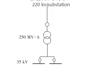
A solar and storage nec photovoltaic power plant with a total installed PV capacity of 250 MW is used as an example for research and analysis, and 10% of the installed capacity is equipped with energy storage. According to the installed capacity, the current situation of the power grid and the planning, it is proposed to send out one 220kV line.
The relevant main equipment and parameters are as follows: the main transformer is a single double-winding double-branch on-load regulator transformer with balanced winding of capacity 250 MV-A. The ratio of the on-load regulator transformer is 220±8×1.25%/37+10 and the impedance voltage percentage Ud=18%.
PV box-type transformers using 79 double-winding box transformers of 3.15 MV-A with a ratio of 37±2×2.5%/0.8 and an impedance voltage percentage Ud=7%; PV collector lines mostly using cables of type ZC-YJLHY23-26/35kV-3×500, totalling 79 km.
Energy storage box transformers using 10 double-winding box transformers of 2.5 MV-A capacity, with a ratio of 37±2×2.5/0.36; impedance voltage percentage Ud=6%.
The energy storage collector line mostly uses the type ZC-YJLHY23-26/35k V3-×120mm2 cable, total 8km 220k V transmission line is 2×JL/G1A-300, 19km. reactive power compensation required for each bus section is calculated according to the PV and energy storage box transformer and collector line losses and apportioned main transformer losses and apportioned line losses brought together by each bus section. The electrical main wiring of the project booster station is shown in Figure 1.
The reactive power losses are calculated according to the relevant calculation formulae in the literature .
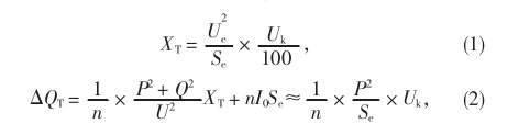
In Eq. (1)-Eq. (2), XT is the famous value of transformer reactance, Ω; Ue is the rated voltage of the transformer, kV; Se is the rated capacity of the transformer, MVA; Uk is the percentage of impedance voltage.
ΔQT is the reactive power loss of the transformer, Mvar; n is the number of transformers running in parallel; P is the active power passed, MW; Q is the reactive power passed, Mvar; U is the transformer terminal voltage, kV; I0 is the percentage of no-load current of the transformer.
In this example, a single PV box-type transformer P=3.125MW, Se=3.150MV-A, n=1, Uk=7%, the reactive power loss of a single PV box-type transformer is calculated as 0.217Mvar; a single energy storage box-type transformer P=2.5MW, Se=2.5MV-A, n=1, Uk=6%.
Substituting into formula (2), the reactive power loss of single energy storage box-type transformer is calculated as 0.15Mvar; each section of 35kV bus in the booster station collects 40 PV box-type transformers and 5 energy storage box-type transformers, and the total box-type transformer reactive power loss of each section of 35kV bus is 9.43Mvar.
3.2.2 Calculation of reactive power loss in the collector lines
The power of the PV power generation unit is inverted and boosted by the inverter and box transformer and then sent to the boosting station through the collector line. The collector lines of photovoltaic power stations generally use cables, and the reactance of the cables is much smaller than the resistance, so only the charging power of the cables is considered. The charging power is calculated by the formula:
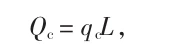
In formula (3), Qc is the charging power, Mvar; qc is the charging power per kilometre, Mvar/km; L is the cable length, km.
For the PV collector line with a cross-section of 3×500mm2, qc is 0.098Mvar/km; for the energy storage collector line with a cross-section of 3×120mm2, qc is 0.060Mvar/km. for the 3×120mm2 cross-section cable used for the energy storage collector line, the value of qc is 0.060Mvar/km.
Substitute the above variables into the formula (3), the calculated charging power of the 35kV-Ⅰ mother collection line is 4.16Mvar, and the charging power of the 35kV-Ⅱ mother collection line is 4.20Mvar.
3.2.3 Boost transformer reactive power loss calculation
The photovoltaic power gathered by the 35k V collector line needs to be boosted by the step-up transformer. The reactive power loss of the step-up transformer is calculated as follows.
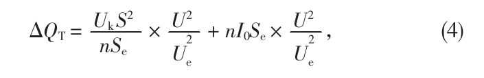
where the voltage is considered to be unchanged, taking U ≈ Ue, which can be simplified as:
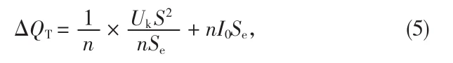
where the value of I0 is small and equation (5) can be simplified as:
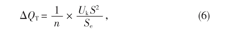
In formula (4) – formula (6), S is the total passing capacity of the transformer, MV-A; n=1, Uk=18%, I0=100%; S=Se=250MV-A; U=Ue. The reactive power loss of a single 250MV-A main transformer is 45Mvar, and the reactive power loss apportioned to each 35kV bus section is 22.5Mvar.
3.2.4 Calculation of the reactive power loss of the transmission line
After the main transformer has been stepped up, the power is finally connected to the grid via the transmission line.
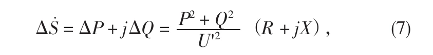
where the reactive power losses can be simplified as
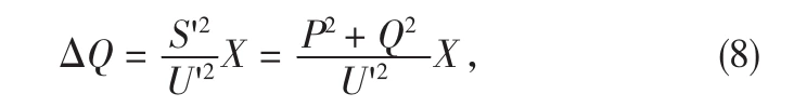
In Eq. (7)-Eq. (8), ΔS is the apparent power loss, MV-A; ΔP is the active power loss, MW; ΔQ is the reactive power loss of the sending line, Mvar.
U’ is the voltage of the sending line, kV.
R is the resistance of the sending line, Ω
X is the line reactance, Ω.
S’ is the total throughput capacity of the sending line, MV-A.
Considering the role of solar and storage nec energy storage device for peak regulation, it is considered that the storage device is charging state when the PV is in full power; when the PV output is 0MW in the evening peak, the storage device is generating state, so the maximum transmission capacity that may occur on the transmission line is when the PV is in full power.
For 250MW of installed PV capacity, taking into account the power factor of 1, Q to take 0Mvar, P = 250MW, 220kV wire model 2 × JL/G1A-300, its unit length reactance of 0.309Ω/km, line length 19km, can be derived from X = 5.87Ω, U ‘= 220kV.
Substitute the above parameters into formula (8), the reactive power loss without considering the line charging power is 7.58Mvar. Considering the existence of charging power of the overhead line, its charging power per unit length qc = 0.19Mvar/km, L = 19km; substitute into formula (3), the charging power is 3.61Mvar.
After deducting the charging power from the reactive power loss of the transmission line, the reactive power loss of the line is 3.97Mvar and the charging power is 3.61Mvar when delivering 250MW capacity, and this needs to be converted to each 35kV bus section.solar and storage nec
According to section 6.2.3 in the literature [2], for PV power stations connected to the grid via voltage levels of 110 (66) kV and above, the reactive power capacity configuration shall meet the following requirements.
a) the capacitive reactive power capacity can compensate the sum of the inductive reactive power of the converging lines in the station, the main transformer and half of the inductive reactive power of the transmission lines from the PV power station when the PV power station is in full generation.
b) Inductive reactive power compensation compensates the sum of the PV power station’s own capacity charging power and half of the charging power of the PV power station’s sending line.
For the apportionment of the charging power of the sending line, due to the charging power of the sending line and the transmitted power reactive power, half of the charging power of the sending line should not be apportioned to each section of the 35kV bus after it is taken into account according to the specification.
Therefore, the charging power of each 35kV bus should be considered separately for the charging power of the collector line and the sum of half of the charging power of the sending line.
After the above calculation, when the PV plant is fully developed, the inductive losses of the PV and storage devices, the collector lines, the main transformer and half of the inductive power losses of the sending lines are taken into account and converted to each 35kV busbar, the total reactive power loss of the 35k VI busbar is 29.75Mvar and the total reactive power loss of the 35kV-II busbar is 29.71Mvar.
When the output of the PV power plant is 0MW, the charging power of the collector line and half of the charging power of the transmission line are taken into account, the total charging power of the 35kV-I bus is 5.96Mvar, and the total charging power of the 35k V II bus is 6.00Mvar.
Therefore, the 35kVI bus and II bus on the LV side of the main transformer need to be equipped with dynamic and continuously adjustable reactive power compensation devices with an effective compensation capacity of not less than 30Mvar (capacitive) to 6Mvar (inductive). The dynamic reactive power response time of the photovoltaic power station should be no longer than 30ms.
The calculation of the reactive power compensation capacity has been carried out in conjunction with the actual project of solar and storage nec, which is of guidance for the configuration of the reactive power compensation capacity of similar projects.
In particular, the reactive power compensation capacity of the solar and storage nec needs to be able to compensate for the reactive power losses of the electrical equipment and the reactive power compensation device should be able to achieve dynamic continuous regulation in order to control and network voltage, and the regulation speed should be able to meet the needs of the voltage regulation of the grid, so it is advisable to equip dynamic reactive power compensation devices. For solar and storage nec the reactive power loss of the delivery line is calculated, due to the peaking effect of energy storage, when the PV is fully developed, the storage power station is in charging or standby state, the maximum transmission power that may occur on the delivery line is the PV full development capacity.
Download Resource
Table of Contents Selecting the right pad-mounted transformer requires careful consideration of several critical

The primary function of the pad mounted transformer is to serve as a critical distribution

A pad mounted transformer operates through electromagnetic induction, serving as a crucial distribution component that
After filling in the contact information, you can download the PDF.