How to Choose Pad Mounted Transformer?
Table of Contents Selecting the right pad-mounted transformer requires careful consideration of several critical
ELECTRIC, WITH AN EDGE
As the number of electric vehicles (EVs) increases, public and private electric charging stations face challenges like low distribution transformer load factors and low charging pile utilization rates. A shared EV charging system design based on public distribution networks aims to address these issues. The system leverages the remaining capacity of the public distribution transformer to allocate DC charging piles, schedules charging based on vehicle owner reservations and public EV charging station models, and dynamically regulates the operating power of each charging pile by collecting real-time transformer load data. This shared charging system enhances charging opportunities for vehicle owners, improves distribution transformer and charging pile utilization rates, and stabilizes distribution transformer load factors.
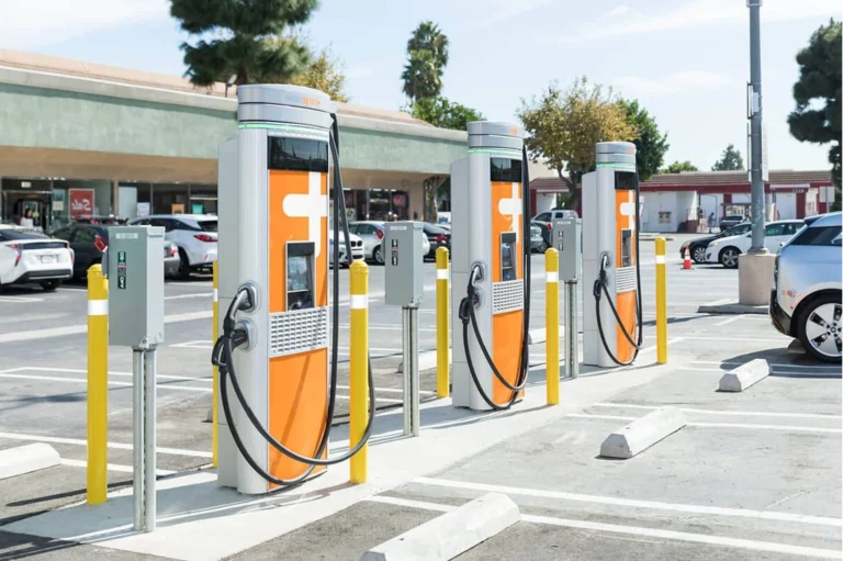
Both the DC charging station of the public electric charging station and the Private electric charging station suffer from low load factor of the distribution transformer and low utilisation rate of the charging piles. To address these problems, the design of a shared electric vehicle charging system based on the public distribution network is proposed. The system makes use of the remaining capacity of the public distribution transformer to allocate DC charging piles, schedules them according to the reservation order of vehicle owners and the scheduling model of public electric charging stations, switches the chargers to the corresponding electric vehicles in turn, and finally dynamically regulates the operating power of each charging pile by collecting real-time transformer load data. The shared charging system increases the charging opportunities for vehicle owners, improves the utilisation rate of distribution transformers and charging piles, and stabilises the load factor of distribution transformers.
With the continuous increase in electric vehicle ownership comes the growing problem of charging difficulties, which is limited by charging equipment, sites, investment and grid access conditions, resulting in a low number of charging piles, difficult queues, and the emergence of slow charging speeds and low equipment utilisation. There are two traditional charging models, one is the public electric charging station and the other is the private electric charging station;
Most of the public electric charging stations are invested and planned by the commercial sector or the government, and use DC charging piles of several tens of kilowatts to connect to the grid through special transformers. Most of the private charging stations use AC charging with a power of less than 10kW and are connected to the grid through a public transformer distribution station.
Although private charging stations are mostly used at night to avoid conflicts with the peak load of residents, the number of charging stations allowed to be connected is limited to ensure the reliability of electricity for residents throughout the day, which reduces charging opportunities. This is a huge waste of resources. In summary, there is an urgent need to address how to improve the utilisation and efficiency of public transformer stations for electric vehicle charging.
In response to the actual needs of the site, the following main improvements have been made to the shared electric vehicle charging system compared to the traditional low-voltage distribution network. The electrical system diagram of the distribution station is shown in Figure 1, with 1 being the public distribution transformer, 2 being the transformer voltage AC bus, 3 being the power user AC bus, 4 being the power user total metering transformer, 5 being the charger AC bus, 6 being the public ev charging stations, and 7 is the charger DC busbar.
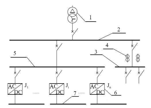
As can be seen from Figure 1, the system consists of two main parts: the conventional power user module and the electric vehicle charging module. The conventional power user module supplies power to a fixed public user, with a total power user metering transformer on the power user AC bus; the electric vehicle charging module supplies power to a shared charging system, where the charger is connected in parallel to the charger AC bus via an AC circuit breaker.
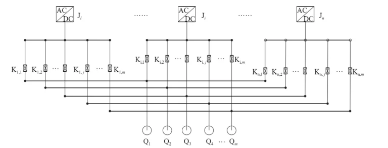
Figure 2 shows the wiring diagram of the chargers and charging guns. From the diagram it can be seen that the shared electric vehicle charging system is configured with n identical power controllable DC chargers, m DC charging guns with communication and mechanical locks and n-m controllable DC switches, with the controllable DC switches on the DC bus of each charger connected to the charging guns in sequence.
The charging monitoring and management module is used for data acquisition and functional control of the electric vehicle charging system and consists of an electrical monitoring device and a human-machine interaction device; the charging monitoring device is connected to all chargers, controllable DC switches, charging guns and the human-machine interaction device for communication via a communication cable, and the current and voltage are collected via a power secondary cable connected to the power user’s total metering transformer.
The monitoring device mainly collects information on the operating status of the charger and issues control commands, collects information on the opening and closing status of the controllable DC switch and issues opening and closing commands, collects information on the battery status of the electric vehicle and issues opening and closing commands for the charging gun, and interacts with the information displayed on the HMI and the owner’s operating commands.
During the regulation of the charging system, the monitoring and management module charges the electric vehicles in the order of the owner’s reservation, all public ev charging stations are activated in turn in the order of the previous stoppage, and the charging power of the kth charger among all the operating chargers is controlled at time t:

where PJk (t) is the charging power of the kth started charger among all running chargers at time t; Pck (t) is the charging power requirement value of the electric vehicle connected by the kth started charger among all running chargers at time t; PE is the rated power of the public distribution transformer; Py (t) is the AC bus of the electricity consumer of this public distribution transformer at time t Real-time power; x is the number of all chargers in operation at time t, 0 ≤ x ≤ n.
In the model, the charging system controls the charging power of the chargers to reach the vehicle charging power requirement as far as possible, and limits the charging power of the last charger to be started if the load on the utility distribution transformer reaches its rated value. The distribution transformer, charger and electric vehicle battery are prevented from being overloaded with the constraint that

Where PJe is the rated power of the charger; Pce is the rated power of the electric vehicle battery charge.
The charging system regulation and control strategy is used to control the whole system electrical equipment operation process, and its detailed steps are as follows.
Step1: Determine whether there is an electric vehicle that needs to be charged. When the charging monitoring device collects that there is a vehicle successfully booked for charging, it means that the electric vehicle needs to be charged by the connected charging gun, and vice versa, the charging of all electric vehicles has been completed.
Step2: Select the next vehicle to be charged. The first vehicle to complete the booking will be the first to start charging after that.
Step3: Determine if there is a charger available to charge the next EV. When a charger is stopped and all controllable DC switches on the DC bus of this charger are off, then the charger can charge the next EV, otherwise no charger can charge the next EV.
Step4: Select the charger to charge the next EV. Sort the chargers in Step3 that can charge the next EV by the time they finished the last charging job, and use the charger that finished the last charging job earliest as the charger that can charge the next EV.
Step5: Switch the controlled DC switch and connect the public electric charging station to the charging gun on the next vehicle.
Step6: Determine the power of the charger according to the “public ev charging stations scheduling model” in 2.1 and charge until the end.
Click on “Charge” in the HMI, check whether the estimated queuing time displayed in the HMI meets the demand, if it does not meet the owner’s usage requirements, stop the operation and end the charging plan; if the bookable time meets the owner’s usage requirements, select the available charging gun (unlocked charging gun) in the HMI and insert it into the car. If the time available meets the owner’s requirements, select the available charging gun (unlocked gun) in the HMI prompt and insert it into the vehicle charging port.
If it does not pass any of the self-tests, the charging gun is replaced; if it passes both self-tests, the HMI displays the estimated charging settlement time and cost.
If the owner does not agree to the estimated charging settlement time and cost, no subsequent operation will be performed and the booking will end;
If the vehicle owner agrees to the estimated charging settlement time and cost, he/she confirms the charging appointment on the HMI and authorises payment, and charging is automatically carried out in the order of the appointment.
The monitoring device receives the charging person’s command to “charge” on the HMI. The monitoring device determines the available charging guns (including those not plugged into the car and those plugged into the public electric charging station but not locked) and the estimated queuing time and displays them on the HMI. This is displayed in the HMI.
After the monitoring unit has received the charge gun number selected by the owner in the HMI, it starts a communication self-test with the battery management unit of the electric vehicle, and if the communication self-test is not passed, it prompts the HMI to change the charge gun; if the communication self-test is passed, the monitoring unit controls the mechanical locking of the charge gun.
If the communication self-test is passed, the monitoring device controls the mechanical locking of the charging lance. Then, it starts an out-of-operation charger or temporarily calls a running charger to switch the corresponding DC switch and carries out a self-test of the charging circuit of the electric vehicle by means of the selected charging lance.
During the self-test, the monitoring device compares the last charging voltage and current information received from the communication line, and if the charger provides the same current and voltage as the car, the self-test is passed; if not, the self-test is not passed and the human-machine interface prompts the replacement of the charging gun.
After the self-test of the charging circuit of the charging gun has passed, the monitoring device reads the data such as the amount of charge needed in the car battery information, predicts the end time of charging and the electricity charge and displays it on the HMI; afterwards, if the HMI does not receive the authorisation to pay for the charging appointment from the car owner within the specified time, it unlocks the mechanical lock of the charging gun and ends this appointment; if the HMI receives the authorisation to pay for the charging appointment from the car owner, it keeps the mechanical lock of the charging gun closed. Then the monitoring device will start the corresponding controllable DC switch and charger and control the charging power in accordance with the “Charging System Regulation Method” and the queuing order in this paper, until the electric vehicle is fully charged, and the mechanical lock of the charging gun will be unlocked after the monitoring device has deducted the actual amount of electricity charge, ending the charging.
The mode of sequential cyclic reservation and sharing of charging guns proposed in this paper can provide users with a prediction of charging time periods and automatically start charging in sequence after completion of inserting the charging gun as well as unlocking the charging gun after it is fully charged, so as to realize unmanned automatic installation of rotating charging, increase charging opportunities and improve the efficiency of reservation charging; at the same time, it tracks the overall supply capacity of the public distribution transformer and regulates the power of all chargers to the power allowed by the distribution At the same time, it tracks the overall supply capacity of the utility distribution transformer, regulates the power of all chargers to the power allowed by the distribution transformer, makes full use of the power supply capacity of the distribution transformer, and reduces the number and time of charger outages, improves the utilisation rate and time of charging equipment, stabilises the load factor of the distribution transformer, and increases the reliability and economy of the grid.
Download Resource

Table of Contents Selecting the right pad-mounted transformer requires careful consideration of several critical

The primary function of the pad mounted transformer is to serve as a critical distribution
A pad mounted transformer operates through electromagnetic induction, serving as a crucial distribution component that
After filling in the contact information, you can download the PDF.