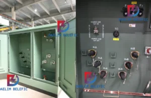
How to Choose Pad Mounted Transformer?
Table of Contents Selecting the right pad-mounted transformer requires careful consideration of several critical
ELECTRIC, WITH AN EDGE
As the leading equipment in the power system, large power transformers generally use oil-immersed, forced oil circulation cooling or natural air cooling. Oil Filled Transformer overhaul cycles are generally above 10a.
The daily maintenance workload of Oil Filled Transformer and reactor is relatively tiny. Still, problems such as rising gas content in Oil due to broken oil pillow capsules and continuous oil seepage at the locating pin hole of oil tank body bonding seam are frequent. More typically, the analysis and treatment of the above problems are briefly discussed.
One frequent breakage of the oil pillow capsule causes a rapid increase in insulating oil gas content.
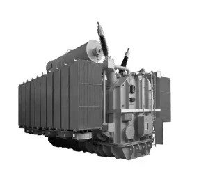
Large oil-immersed transformer, according to the process requirements before the commissioning of strict drying, insulating oil vacuum filtration, and hot oil circulation, oil gas content is generally controlled at 0.5% or less.
After the Oil Filled Transformer is put into operation, the high voltage field strength environment will cause the decomposition of the insulating oil, and the gas generated will be dissolved in the insulating oil, which will increase the gas content of the insulating Oil. Under the condition that no fault occurs and the body is well sealed in all parts, the rate of gas content increase is prolonged, showing a long-term slow increase trend.
The rapid increase of gas content in the Oil is usually caused by the direct entry of external air, which is reflected in the high range of O2 and N2 in the dissolved gas components.
The high electric field strength environment in Oil Filled Transformer makes it easy to precipitate the gas dissolved in the insulating oil, which gradually forms bubbles and adheres to the insulation surface, causing the local insulation strength to drop, accelerating the aging speed of the oil-immersed transformer insulation materials, shortening the service life of the main transformer, and even causing the primary insulation to break down.
The 500kV Oil Filled Transformer should contain less than 3% of gas in the insulating oil during operation.
Transformer body sealing defects usually manifest as oil leakage at fault. Generally, through a comprehensive appearance inspection, it can be found more obviously and dealt with in time. However, for the capsule installed in the oil pillow inside the broken, only power outage inspection, equipment downtime is more extended, seriously affect the utilization of equipment, power supply safety and reliability has a particular impact.
Through multiple oil-immersed transformers and reactor capsule breakage inspection, analysis and processing, it can be determined that the direct cause of the oil pillow capsule breakage for the capsule contact with the oil level meter sharp and burr part, the capsule a point scraped, punctured, and with the completion of oil injection capsule broken vacuum expansion and make the puncture point along the direction of development quickly torn, so the rupture Flush, the end of the tear marks. After the operation of the equipment, the capsule breathes frequently, and the rupture is gradually enlarged.
Oil injection to complete the capsule vacuum breakage is an essential process after oil-immersed transformer oil injection. The capsule breakage problem was dealt with frequently in 2016-2020 because, on the one hand, some of the capsules had already broken during the installation of the equipment. With the increase in operation time, it was manifested through the phenomenon of rising gas content, and centralized treatment was carried out.
On the other hand, the Oil Filled Transformer oil chromatography online monitoring device was used, making it easier to determine the cause of high gas content and more time to detect and deal with it. When dealing with the continuous express rise of gas content in the primary transformer oil or other problems requiring oil pillow evacuation, the sensitive and burr parts of the oil pillow oil level gauge are simultaneously investigated and polished to eliminate the defects that may cause damage to the capsule. The practice has proved that it can effectively reduce the probability of capsule breakage to ensure the long-term safe and stable operation of the transformer.
The transformer tank body is divided into two parts: upper and lower. After the internal structure is installed, the upper tank is connected to the lower tank through several positioning pins. A seal is pressed on the inside of the positioning pins as the primary oil leakage prevention measure. After the positioning installation is completed, the upper and lower ends of the positioning pin holes are welded shut, and the upper and lower boxes are closed at the joint seams.
Since its commissioning, oil leakage has occurred at the positioning pin holes of the union joints of multiple Oil Filled Transformer tanks, mainly at the lower end pin holes, and the rate of oil leakage is not high but persistent for a long time. The surface paint was removed, and a surface PT inspection was performed on the pinhole welding, which revealed the existence of gaps or welding defects and sand holes in the pinhole welding.
In 2015, combined with the primary transformer outage maintenance, the 13 pinhole oil seepage points of the 5 leading Oil Filled transformers were patched on-site. No oil leakage occurred in the pin holes after the welding, and the treatment effect is good. The defect of any point of the seal ring between the upper and lower box of the main transformer will cause its seal to be poor, and the transformer oil inside the tank will seep out and accumulate in the cavity area between the outer side of the seal ring and the upper and lower box combination.
This area pinhole, box body combination seam is used to achieve sealing welding method; welding process quality directly affects the sealing effect. Robots in the main transformer manufacturing plant are welding the upper surface of the pinhole and the upper and lower box joints, and the overall welding process is precisely controlled. The quality is more reliable, so oil leakage caused by the welding quality rarely occurs.
The robot can not complete the welding work on the lower end of the pinhole but use manual back welding, which increases the welding difficulty. The process quality is affected by the technical level of the welders, so there is more oil leakage.
The following monitoring means are mainly adopted.
1) Grounding the end screen of the casing directly using a ground wire for reliable grounding.
(2) Reliable sealing of the end screen grounding prevents moisture from entering.
(3) Regular infrared inspection of oil-immersed transformer and high-voltage casing to detect temperature abnormalities in time.
4) Regularly measure the grounding current value and record the analysis data to strengthen the monitoring and analysis of the operational data of the main transformer, find abnormalities and deal with them in time.
After 1a of tracking monitoring and analysis, the end screen grounding current fluctuates between 32 ~ 33mA, with no rising or falling trend. At the same time, the main transformer operating data is standard, and the operation is good.
Comprehensive judgment, the end screen end cover is not tightened or not sealed tightly, causing the end screen surface and the surface layer of moisture, which may be the main reason for the casing dielectric loss value increased.
In the rainy season, the end screen is operated under high humidity conditions for a long time, and its surface and surface layer will have an inevitable increase in medium humidity (but the moisture is not severe, and the primary insulation is not significantly affected) so that its dielectric loss value increases significantly.
The simple use of hot air for a short drying time can reduce the medium’s surface humidity. Still, it is difficult to reduce the internal medium moisture, so after a short time of drying, its dielectric loss has a slight reduction (0.643% to 0.630%), but the overall decline is not apparent.
After the reliable sealing of the end screen, the casing was operated continuously for 1a, during which the water in the casing medium continued to precipitate and evaporate by relying on the oil temperature and the operating temperature of the casing itself, and the medium humidity continued to decrease. Thus the value of the dielectric loss during the test in 2018 was closer to the value tested in 2016.
The casing dielectric loss test results in 2019-2021 are not significantly abnormal compared with the test data in previous years (except in 2017), indicating the possibility of elevated casing dielectric loss caused by moisture in the end screen has further increased.
With advances in testing technology, casing insulation diagnosis can be performed by adding FDS low-frequency band testing for suspected or important equipment casing to identify and address potential abnormalities promptly.
Using the existing test equipment of the power plant, it is concluded through a series of tests.
Two identical insulation oil samples are taken, and before degassing, oil sample A is injected with 5ml N2 (standard degassing method), and oil sample B is injected with 5ml He.
At a specific temperature, the saturation concentration of the gas in the liquid is proportional to the partial equilibrium pressure of the gas at the liquid surface (Henry’s law). The reason for injecting 5ml of N2 and He is to reduce the partial stress of other gases on the surface of the oil sample so that the gases dissolved in the oil can be more easily taken out. After degassing, 1ml of the degas was taken for a chromatographic test.
It was found that the H2 content of oil sample A was significantly lower than that of oil sample B, which proved that He could be mistakenly detected as H2 during regular chromatographic monitoring.
When 1ml of He with higher purity was injected separately, it was found that only the H2 content was higher in the chromatographic monitoring results (some of the CO and CO2 present may be due to some air entering during the gas extraction process). It can be seen from the peak pattern of the two tests that the H2 retention time of oil sample A is 52s, and the overall peak pattern of oil sample B moves forward and even covers the oxygen wave peak, with a more significant wave width, higher height, and more considerable measured value. The final retention time is 56s, which is still within the retention time of H2 detection and is counted in the H2 content, which finally makes the measured H2 content increase significantly.
Injecting 1 ml of He alone, the wave position overlapped mostly with the H2 wave position. It shifted slightly forward overall, with a retention time of 57s, which was within the H2 detection retention period and eventually detected by the system as an H2 peak. To further verify this hypothesis, tests were conducted on the alarm primary variable oil sample using a column (5A) packed with a packing capable of separating H2 and He (with different peak emergence retention times). First, a single gas peak time test was performed.
One sample of H2 and one sample of He with high purity were collected, and their peak times were measured. The peak retention time of H2 was 4.08 min, and that of He was 3.71 min (Figure 3). The peak retention times of the two gases were different, and the gas type could be determined from the peak retention times of the gases.
When the gas was removed from the oil-immersed transformer, an unknown peak was seen in front of the peak position of H2 (4.08min), and the peak retention time was 3.75min.
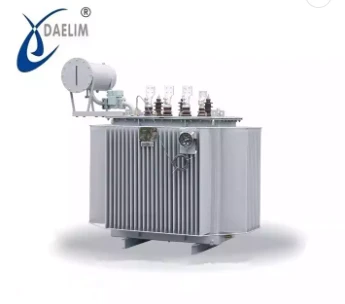
The main introduction of the power plant oil-immersed transformer and reactor since the commissioning of some of the more typical problems occurred in the analysis and processing process. In recent years, with the increasing operation time of the equipment, the aging of the seals also began to appear, especially the seal at the flange of the oil pillow and capsule connection, there is a loss of elasticity, the sealing effect decreases, and other problems, but also become the cause of the increase of gas or water in the oil.
Download Resource

Table of Contents Selecting the right pad-mounted transformer requires careful consideration of several critical
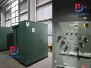
The primary function of the pad mounted transformer is to serve as a critical distribution
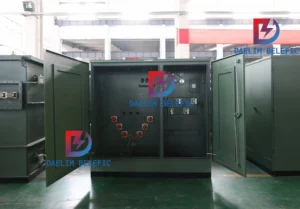
A pad mounted transformer operates through electromagnetic induction, serving as a crucial distribution component that