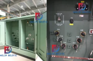
How to Choose Pad Mounted Transformer?
Table of Contents Selecting the right pad-mounted transformer requires careful consideration of several critical factors, as these ground-mounted distribution transformers play a vital role
ELECTRIC, WITH AN EDGE
At present, the construction of the distribution network pays attention to standardization and standardization and strengthens the role of leading and demonstrating models to improve the quality of construction. Based on work experience, the author puts forward the following items that should be paid attention to when installing distribution transformers for reference.
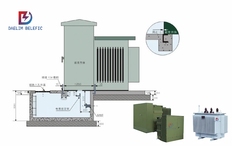
(1) The power distribution transformer platform on the column adopts the equal-height pole method, and the electric pole adopts a non-prestressed concrete pole. Double cross arm and double vertical insulators should be used at the top of the main and auxiliary poles.
(2) Two parallel groove clamps should be used to connect the high-voltage down conductor to the 10 kV line, with the tail facing the power receiving side.
(3) When selecting wires, use JKLYJ-10/50 overhead insulated wires from the main trunk line to the upper pile head of the drop-out fuse, and use JKTRYJ-10/35 overhead insulated wires from the lower pile head of the drop-out fuse to the distribution transformer.
(4) All wiring should be straight, the arc should be beautiful and consistent, and the distance between the cross arms should meet the typical design requirements. Except for the drop-out fuse cross arm which is installed on the high voltage side of the distribution transformer, all the other cross arms are installed on the low voltage side of the distribution transformer. Drop-out fuses and test grounding rings should be installed on the high-voltage side of the distribution transformer. The distance between the insulation piercing grounding clamp and the pile head of the fuse should be greater than 700 mm.
(5) The installation of the arrester should be as close as possible to the distribution transformer, and its grounding down conductor should be connected to the neutral point of the secondary side of the distribution transformer and the metal shell of the distribution transformer.
(6) The mounting bolts should use “two flats and one elastic double nut”, the screw fasteners should be exposed in the same way, and the washers should be square.
(7) Install warning signs of “No Climbing, High Voltage Danger” on the poles on both sides of the platform, with a size of 300 mm×300 mm. The color of the rectangular backing of the prohibition sign is white, the round frame with slashes is red, the sign symbol is black, and the auxiliary sign is white on a red background with bold letters. The nameplate is installed on the distribution transformer support on the right side of the front of the stand. The size of the nameplate is 300mm×240 mm (without frame), with red letters on a white background and bold letters. The upper edge of the installation is aligned with the upper edge of the distribution transformer support. And fix it on the support with a steel belt.
(8) The low-voltage integrated distribution box adopts suspended installation, and the lower edge is not less than 2.0 m from the ground. It can be appropriately increased if there are flood control requirements. In D and E power supply areas such as rural areas, farming, and pastoral areas, the height of the lower edge of the low-voltage integrated distribution box can be reduced to 1.8 m. The inlet and outlet of the integrated distribution box shall be blocked with fire-resistant mud and other materials.
(9) The grounding body shall be laid in a closed loop around the distribution transformer, with more than 2 vertical grounding electrodes, and the buried depth of the grounding body shall not be less than 0.6 m. The grounding flat iron should be installed on the other side of the low-voltage outlet of the integrated distribution box. The grounded flat iron shall be painted with yellow and green marking colors. Reflective stickers should be attached to the root of the pole.
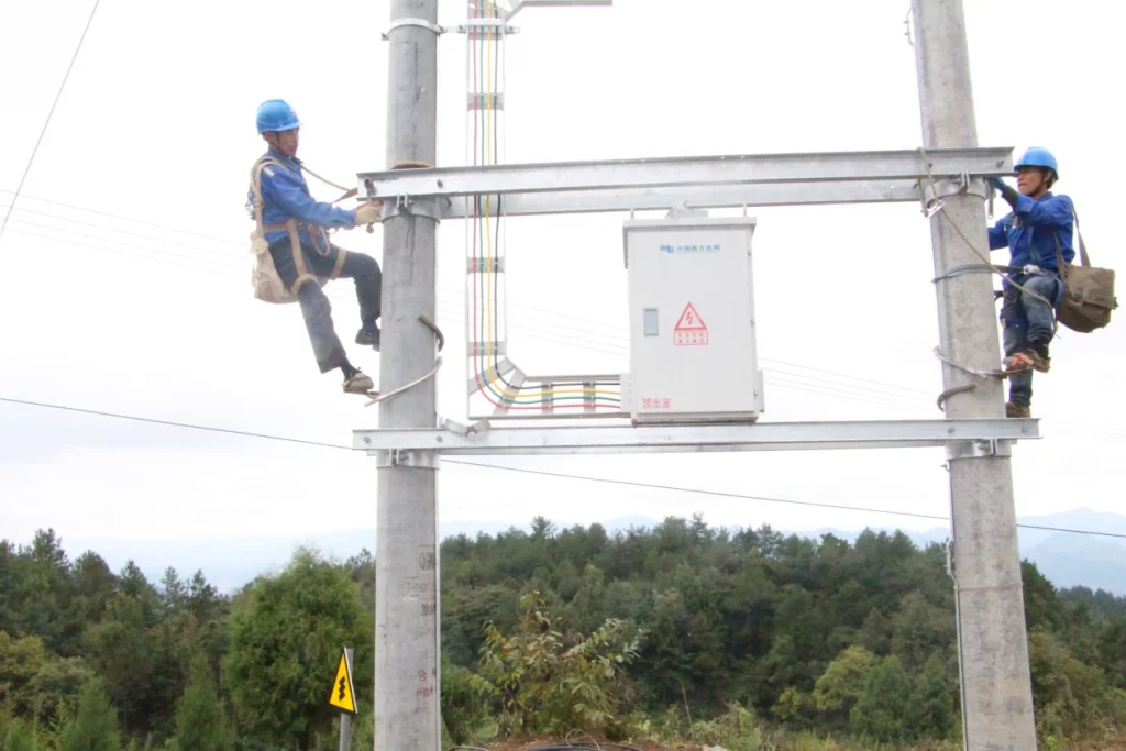
The distribution transformer installation project in the distribution network project has a large total number of small units, many points and a wide range of construction teams with different levels of management is more common.
Generally speaking, the operation process of distribution transformer installation project is: tower assembly → transformer installation → lightning arrester installation → fuse installation → JP cabinet installation → grounding device installation.
The supervision method of project quality control of distribution transformer installation project mainly adopts the combination of active control, active control and passive control to manage, through the organic combination of three stages of pre-control, check and track, timely detection of problems, problem solving and strict control afterwards to carry out supervision work.
In addition to the conventional review of the construction unit personnel qualifications, construction programs (work instructions), raw material quality assurance information, supervision process to take the necessary means such as side stations, inspection and parallel inspection, supervisors should also focus on the following control.
Foundation pit excavation. According to the specification, 15 m and below the buried depth of cement poles should be 1/10 pole height + 700 mm. cement pole pit ramming level after the installation of the chassis. Must determine the positioning mark of the cement pole grouping, chassis placed in the center of the bottom of the pit, from the distance between the four sides should be the same.
Platform pole in place. The distribution substation adopts the equal height pole method, and the pole adopts non-prestressed concrete pole. Foundation backfill.
Foundation backfill, soil should be broken, the foundation should be tamped in layers, each backfill 300 mm should be tamped once, backfilled concrete pole pit should be set to prevent sinking soil platform.
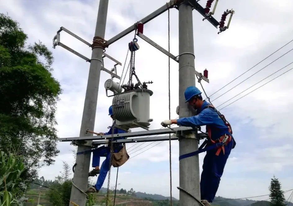
The iron cross-arms and iron accessories used in the line should be hot-dip galvanized, and the cross-arms should be installed squarely and the deviation should meet the specification requirements. The difference in height between the connection of the double pole cross-arms and the pole shall not be greater than 0.5% of the connection distance, and the left and right twist shall not be greater than 1% of the length of the cross-arms.
The vertical distance of transformer channel to the ground is not less than 3.4 m. The root of distribution transformer adopts 2 80 cm long No.10 channel steel to install transformer sideways, and the channel steel shall be fixed with the pedestal when installing the channel steel, one end of the channel steel can be tightened first, and the other side of the hoop is higher than the benchmark height by 5-10 cm, do not close.
After the installation of the channel, the impact base sinks to the reference height, and then tighten the hoop bolts in turn, the clamping screw.
The transformer should be checked before the test report and in place, and the transformer installation should meet the requirements of the design drawings.
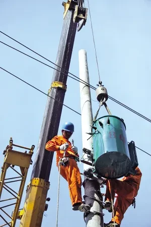
When the high-voltage lead wire is connected with shaped trench clamps, 2 wire connection joints should be used for each phase, and the joints should face the power side, and the spacing between the two trench clamps should be 100 mm.
The spacing between vertical cable fixing brackets should be no more than 1.6 m. The cable should be installed with insulating mat when it is fixed on the bracket. The cable should be firmly fixed and evenly stressed.
Overlap should be firmly connected, lead, cable lap before the wire, cable, etc. should be organized and level, not using bolts to force the wire or cable and equipment pile head lap, can not be in line, the use of external wires to change the direction of the pile head to meet the lap requirements.
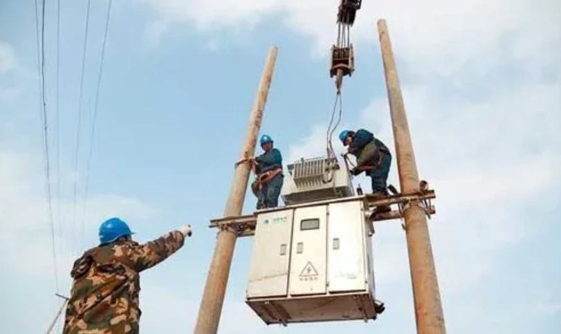
All exposed parts should be installed with insulation sheath, and the sheath should be installed to straighten out the joint and not produce a lap angle.
After installation, if the insulation sheath does not reach the insulation cover range, other insulation methods must be used to repair and perfect. Distribution transformer pile head sheath shape should pay attention to coincide with the shape of the pile head, and reasonable and beautiful shading, shall not be mixed.
Lightning arrester installed on the bracket should be vertical, neatly arranged, and the same height, fixed and reliable. Lightning arrester must be installed straight, the tilt angle should not be greater than 15 °, the tilt should be less than 2%.
Lightning arrester phase distance should not be less than 35 cm. lightning arrester and the electrical part of the connection, should not make the lightning arrester to produce additional stress. The installation position of the arrester should be greater than 0.5 m from the transformer end, less than 4 m.
Lightning arrester lead installation should be short and straight.
Installation of lightning arrester insulation protection, should correctly use a single line or terminal type lightning arrester insulation sheath, lightning arrester side of the line out of the choice of one-way sheath, lightning arrester both sides of the line out of the choice of two-way sheath, is strictly prohibited to mix. Installation fasteners should be correctly in place, phase color and transformer phase consistent.
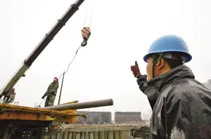
Drop fuse horizontal phase distance should not be less than 500 mm, drop fuse axis and the ground need to be the vertical line angle of 15 ° ~ 30 °. The installation position of the drop fuse should be greater than 0.7 m from the lightning arrester.
Installation of drop fuse lead, connected to leave a margin, wiring pile head and lead connection applications such as wire clips, wire nose, copper and aluminum connection should be transitional measures, fuse up and down the pile head are required to install the shield, is strictly prohibited without crimping directly press the wire into the fuse pile head pressure.
Drop fuse sheath installation, phase color and transformer consistent.
JP cabinet installation should be fixed in the center of the channel steel, using double-headed screw fixed in the channel steel, and JP cabinet bottom to the ground distance of not less than 2 m. JP cabinet in and out of the line cable or insulated line arc droop lowest point, should be lower than JP cabinet in and out of the line hole. JP cabinet in and out of the line mouth must be blocked.
The grounding ring is installed between the lower end of the 10 kV drop and the lightning arrester lead, copper and aluminum trench clamps and wire connection point should be installed with insulation protection cover, the installation point of each phase test grounding ring from the distance to the fixed point of the insulated wire should be consistent.
Grounding network should be set around the substation pole, in a circular arrangement, the depth of the grounding network slot should be not less than 600 mm (for arable land should not be less than 800 mm), the width should not be less than 400 mm.
Vertical grounding body (4) and horizontal grounding body between the use of three-sided welding, welding length should not be less than two times the width of flat steel. Take lap welding between horizontal grounding body, grounding lead line lower end and horizontal grounding body connection, should meet the lap length mark when welding, all welding place should do anti-corrosion treatment.
The lightning arrester grounding, transformer grounding, JP cabinet shell grounding, transformer neutral grounding lead should be four in one, that is, the common introduction of a ground wire. Distribution transformer low-voltage side of the neutral point of the work grounding resistance, generally not more than 4 Ω. The bottom of the three-phase arrester should use BV-35 mm2 copper core insulation shorting into the grounding device.
Line grounding line should be unified from the center of the line direction left 5 cm position to lead down (inside), the lead should be neat and straight, grounding wire using copper and aluminum wire nose crimp, and grounding flat iron bolts connected, grounding flat iron should be 2.7 m above the ground, and brush 20 cm between the yellow and green paint circle. Grounding resistance measurement. Line grounding resistance should be arranged to measure, and the resistance value shall not be greater than 10 Ω.
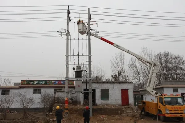
5 m and below the burial depth of cement poles for 1/10 pole height + 700 mm, the allowable deviation of + 100 mm, – 50 mm.
The center deviation of 2.5 m between two pits in the station area should not exceed ±30 mm, and the height difference between the depths of the two pits should not exceed 20 mm.
Take the center of the disk as the center, and draw a circle on the chassis with the radius of the pole root as the radius, as the positioning mark of the cement pole group.
Adopt the equal height pole method, and the electric pole adopts non-prestressed concrete pole.
The chassis is placed at the center of the pit bottom, and the distance from the four sides should be the same.
When the foundation is backfilled, the soil should be broken, the foundation should be rammed in layers, every 300 mm backfill should be rammed once, after backfilling the cement pole pit should be set up to prevent sinking soil platform.
Grounding network groove depth should be not less than 600 mm (for arable land should not be less than 800 mm), width should not be less than 400 mm.
Vertical grounding body (4) and horizontal grounding body between the three sides of the welding, welding length should not be less than 2 times the width of the flat steel; horizontal grounding body between the adoption of lap welding, the use of welding lap length should meet the flat steel lap for its width 2 times, round steel lap length for its diameter 6 times, flat steel and round steel lap length for the diameter of the round steel 6 times.
Grounding ring using copper and aluminum trench line (JBTL-16-120) installed in the 10 kV fall bottom end and lightning arrester lead between, after installation is completed from the fall bottom arc lead should maintain 300 mm clearance distance; grounding network should be cast around the substation pole, is arranged in a circular shape, its side length is 5 m four-sided rounded rectangle; canonical set in the arrester grounding, transformer grounding, JP cabinet shell grounding, transformer Neutral point grounding lead should be four in one, that is, the common introduction of 1 grounding line.
Double pole transformer stand should use channel steel, channel thickness should be > 10 mm, and hot dip galvanizing treatment, stand from the ground should not be less than 2.5 m, the horizontal tilt should not be greater than the root of the stand open 1/100; stand installation fastened, after checking the qualified before lifting the transformer in place fixed.
Transformer installation should be in accordance with the requirements of the design drawings, column transformer fixing method using 2 pieces of connection piece, 4 double-headed screw fixed in the channel steel, transformer installation should be fixed in the center of the channel steel.
Lightning arrester lead phase spacing should not be less than 300 mm, the distance to the pole body, members should not be less than 200 mm.
JP cabinet in and out of the line using cable, its bending arc is not less than 15 times the diameter, the use of insulated wire, its bending arc is not less than 20 times the diameter, JP cabinet in and out of the line cable or insulated line arc droop lowest point, should be lower than JP cabinet in and out of the line hole.
The construction unit must notify the supervisor in advance (not less than 24 h) to witness or supervise the site of concealed works, important processes, stopping points and side stations.
The quality of distribution transformer installation project by-pass should include the following: civil construction: distribution equipment (box-type transformers, ring network units, cable branch boxes) foundation concrete pouring; pole tower foundation concrete pouring; cable well concrete pouring, etc.
Cable construction: cable intermediate joints (terminal head) production and testing.
Distribution transformer construction: transformer in place.
Distribution equipment: commissioning and testing.
Distribution automation device construction: terminal commissioning.
The quality of transformer installation construction process is influenced by many factors. Engineering supervisors can only ensure the quality of project installation by strengthening the quality control of each construction link in the distribution transformer installation project and ensuring that each process meets the design and specification requirements.
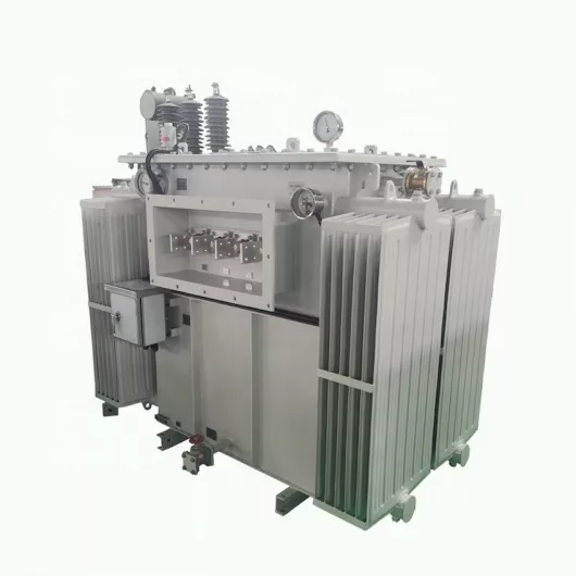
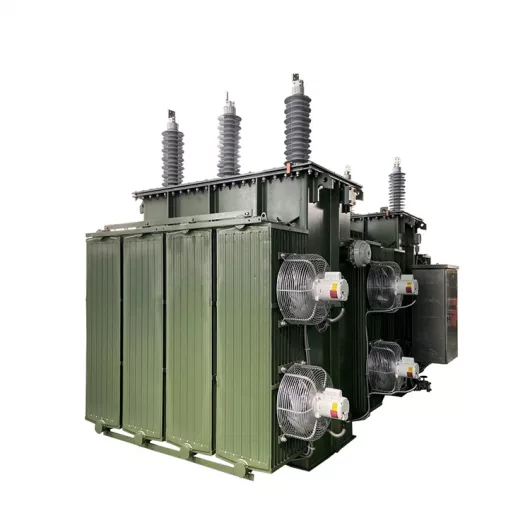
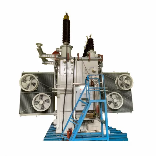
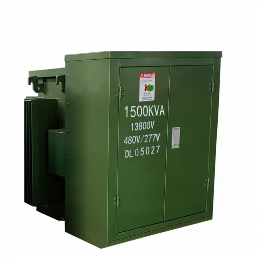

Table of Contents Selecting the right pad-mounted transformer requires careful consideration of several critical factors, as these ground-mounted distribution transformers play a vital role
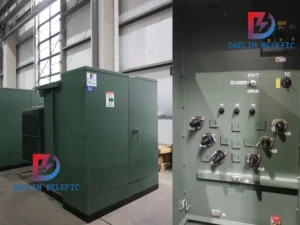
The primary function of the pad mounted transformer is to serve as a critical distribution transformer that steps down higher primary voltage from utility distribution
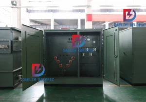
A pad mounted transformer operates through electromagnetic induction, serving as a crucial distribution component that converts high voltage electricity to lower, usable voltages for residential

When looking for the best pad-mounted transformer manufacturer, it’s important to find industry leaders known for reliability and innovative solutions. Pad-mounted transformers are essential in
After filling in the contact information, you can download the PDF.