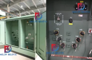
How to Choose Pad Mounted Transformer?
Table of Contents Selecting the right pad-mounted transformer requires careful consideration of several critical
ELECTRIC, WITH AN EDGE
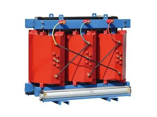
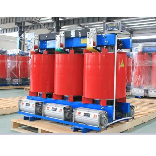
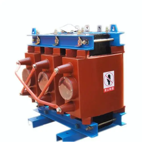
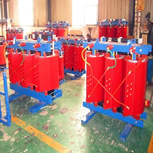
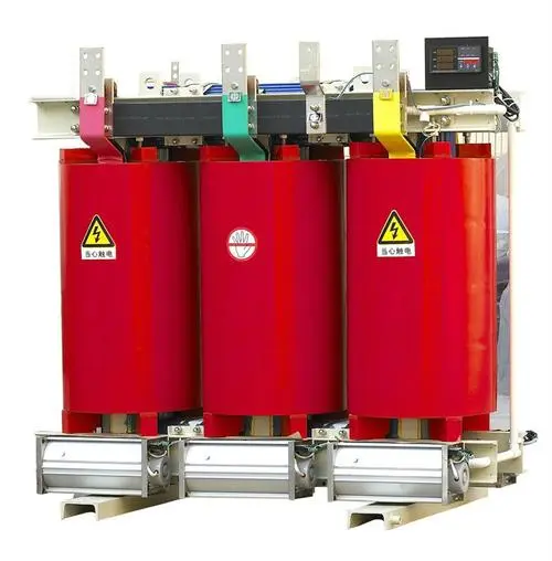
1600kVA Cast Resin Transformer is a dry-type transformer using epoxy resin as casting material.
At the same time, it is also the mainstream dry-type transformer in the international market.
The 1600 kva transformer has the advantages of high dielectric strength, strong short-circuit resistance, and outstanding disaster prevention and energy absorption.
This article will give you a detailed introduction to this transformer.
If you want to find a reliable and reliable transformer manufacturer, Daelim is undoubtedly your best choice. The transformers produced by Daelim meet the requirements of national standards, and have reliable guarantees for product safety and reliability.
Daelim has obtained international certifications such as CSA, IEEE, DOE, IEC, ANSI, etc., to provide you with reliable product quality assurance. More than 16 years of production and design experience to help your grid construction.
1600kVA epoxy resin casting dry type refers to epoxy resin casting dry type transformer (referred to as dry change) with high voltage 10kV, low voltage 0.4kV and capacity 1600kVA.
1600kVA Cast Resin Transformer is a common standardized product that directly supplies power to the distribution network. Transformer is a product that is mass-produced and has a wide range of applications.
The primary side winding (ie high voltage winding) of traditional 1600kVA Cast Resin Transformer generally adopts a single-layer cylindrical structure, and the secondary side winding (ie low voltage winding) adopts a foil winding structure.
The single-layer cylindrical structure is a single-spiral structure winding that cancels the amplitude air channel, and is spirally wound by a flat wire.
Although this kind of winding has a simple structure and is easy to wind, when epoxy resin is poured, it is very easy to block the resin due to the structure of the upper and lower ends of the wires.
The optimized high-voltage winding adopts a double-layer segmented cylindrical structure.
This structure has good winding process and strong short-circuit resistance, but requires reasonable layering and segmentation to ensure that the interlayer voltage, inter-segment voltage, turn voltage and insulation are matched.
The double-layer segmented cylindrical structure is made of round wires or flat wires spirally wound into several layers, and insulating materials and air ducts are placed between the turns of each layer.
As a common standardized product, the 1600kVA Cast Resin Transformer has increasingly higher requirements for its high cost performance.
Therefore, on the basis of the replacement of production equipment and the continuous innovation of process methods, it is very necessary for transformer manufacturers to reduce costs and increase efficiency of previous product designs.
Epoxy resin is a chemical raw material with good fireproof and insulating properties, so it is gradually used in electrical products.
Since AEG developed the first epoxy casting dry changer, the epoxy casting technology has continued to innovate and continue to blossom and bear fruit all over the world. Because my country’s epoxy casting technology is mainly learned from Germany, the vast majority of my country’s production is epoxy resin casting dry-type transformers.
At the same time, because epoxy resin has good insulating properties, it is not easy to deform after molding, and at the same time, it can maintain its own characteristics in humid and dusty environments, so it is very suitable as a casting material for dry-type transformers.
Most of the insulation grades of epoxy resin casting dry change in the initial stage are B grades. At present, the insulation grades of domestic products are mostly F grades, and can also reach H grades according to special requirements.
35kV (individual products have reached 66/77kV) is the highest voltage level of epoxy resin casting dry change, 20MVA is its maximum capacity, and its benchmark impulse level (BIL) does not exceed 250kV.
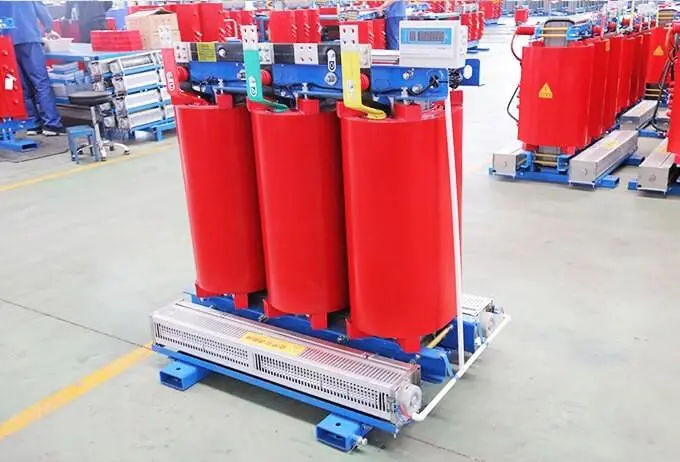
(1)High dielectric strength: It has similar lightning impulse strength to the oil-immersed transformer of the same voltage level and has a dielectric breakdown field strength of 18~22k V/mm.
(2)Strong short-circuit resistance: It is confirmed by the sudden short-circuit test that the casting dry transformer is rarely damaged due to short-circuit. At the same time, the 1600kVA Cast Resin Transformer coil becomes a rigid body after integral casting and heating and curing, so the mechanical strength is high.
(3)Outstanding disaster prevention performance: epoxy resin has flame retardant and flame retardant properties, even if it is accidentally burned, it can be extinguished by itself, which can prevent secondary disasters.
(4)Can be used in harsh environments: Epoxy resin is stable in performance and can maintain its own performance in harsh conditions such as humidity, dust and atmospheric pollution, and will not be abnormal even in extreme humidity environments. In the case of a dry restart, it can also start working again without additional processing. One of the outstanding advantages of epoxy casting dry change is that it can operate under harsh environmental conditions.
(5)Low maintenance workload: The daily maintenance of the epoxy cast dry transformer equipped with a complete temperature control and humidity display system is very low, so it can greatly reduce the maintenance and operation costs.
(6)High operating efficiency and low loss.
(7)Low noise.
(8)Easy to install, easy to debug, light in weight and small in size.
(9)Save floor space, no need for a separate transformer room, and no need for hanging core maintenance. In the production process of epoxy resin casting dry change, it must go through the process of moulding, pouring, curing and so on.
In the early stage of development, most of the cast windings of epoxy cast dry transformers used thick insulation. Thick insulation is to use epoxy resin added with quartz powder. The thickness of the insulation layer is generally 6~15mm, and most of them are B-class insulation.
The segmented cylindrical structure is generally used to make the wire-wound primary side winding, the interlayer insulation is made of alkali-free tape, and the end insulation is made of glass cloth board.
After that, the wound coils are processed by molding, pouring, curing and the like. However, because the heating conditions of epoxy resin and wire will be different, it is easy to cause cracking of the ring insulation layer after the dry operation is heated, and the small air gap formed by this is very easy to cause partial discharge.
The electrical corrosion caused by this partial discharge will also greatly shorten the operating life of the 1600kVA Cast Resin Transformer, and seriously threaten its operating reliability.
Therefore, under the background of continuous upgrading and innovation of products, thin insulating structures have gradually become the mainstream of products.
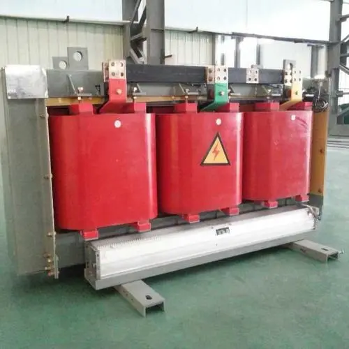
1600kVA Cast Resin Transformers can be divided into the following types according to the winding type:
(1) Both high and low voltage coils adopt wire-wound cylindrical structure. This structure is generally used in large-capacity casting dry transformers. The high-voltage coil generally adopts a segmented cylindrical structure, and the low-voltage coil adopts a multi-layer cylindrical structure.
(2)The high-voltage coil adopts a wire-wound cylindrical structure, while the low-voltage coil adopts a foil-type structure. The foil structure is widely used in dry-type distribution transformers.
The coil of the low-voltage foil structure does not need the process of moulding, pouring, curing, etc. During the winding process, a layer of insulating material needs to be wound between the layers, and after winding, it is only heated and solidified.
The foil coil has high production efficiency and good manufacturability, and can also reduce lateral magnetic flux leakage, reduce axial electromotive force, improve short-circuit resistance, and reduce additional losses.
(3)Both high and low voltage windings adopt foil structure. The capacity of this structure generally does not exceed 2500k VA, and the maximum does not exceed 4000k VA.
The high-voltage coil adopts a segmented cylindrical foil structure, and the low-voltage coil adopts an ordinary foil structure. The segmented cylindrical foil coil is very difficult to manufacture, and its manufacturing equipment and production materials must meet certain standards, otherwise it may affect the product quality.
(4) Winding structure. This product type is the “Thor” series produced by ABB in the 1970s. , The inner film of the high-voltage coil of this structure is an epoxy glass cloth cylinder, which is wound on a winding machine, and the low-voltage winding is an ordinary foil structure. This 1600kVA Cast Resin Transformer has large volume, high manufacturing time and low operational reliability, so its market share is very low.
However, with the number of new 1600kVA Cast Resin Transformers being put into use every year, the failure rate of dry-type transformers has also increased.
Most of the failures are related to temperature, vibration, and deformation, and the research on electromagnetic fields and losses is discussed. The basis of various electrical, magnetic and thermal factors and their interaction in transformers.
The existence of the leakage magnetic field produces a loss effect in the transformer, which is mainly manifested in: the pot current loss in the winding conductor. Due to the existence of the pot current, the distribution of the current density along the cross section of the wire is not uniform, resulting in a squeezing effect;
Due to the uneven distribution of the leakage magnetic field, the induced electromotive force in the winding conductor perpendicular to the direction of the leakage magnetic field is different, resulting in circulating current loss inside the conductor;
The leakage magnetic field also causes stray losses in the metallic structural parts of the transformer.
Due to the uneven loss of turbulent current generated by the leakage magnetic field in the metal structural parts within a certain range, local overheating of these structural parts will be caused.
The thermal energy of the 1600kVA Cast Resin Transformer is deteriorated, which eventually leads to thermal aging and breakdown of the insulating material.
In addition, when the power system is short-circuited, the leakage magnetic field generated by the transient short-circuit current will also generate a certain mechanical force, posing a fatal threat to its insulation and mechanical structure.
This is one of the main reasons that the 1600kVA Cast Resin Transformer cannot operate safely and reliably.
Analyzing the distribution of the transformer leakage magnetic field is the basis for studying the transformer current loss, sudden short circuit with temperature rise and electromagnetic parameters:
The obtained magnetic field distribution can provide a theoretical basis for inspectors to measure electromagnetic values, which is beneficial to reduce the failure of 1600kVA Cast Resin Transformers.
Silicon steel sheet is made by adding a small amount of silicon during the smelting process of steel, which can improve the magnetic permeability, resistivity, reduce magnetic flux leakage and eddy current loss.
At present, most transformer cores are made of silicon steel sheets. SCB10-1600/10 series dry transformers all adopt five-step stacking, similar to circular iron cores with staggered stacking type chip removal structure.
Because the voltage level of the winding is determined, when the core size is determined, the potential per turn of the winding is mainly determined by the magnetic flux density.
The impedance voltage is usually related to the magnetic flux density, and the impedance voltage is generally proportional to the square of the number of turns of the winding, and the number of turns of the winding is generally inversely proportional to the magnetic flux density.
Therefore, when determining the magnetic flux density of the iron core, it is necessary to consider whether the impedance voltage, no-load loss and no-load current meet the design requirements.
Winding is one of the most important features that distinguish 1600kva dry-type transformers from other forms of transformers, and it is also its most important part. The windings of epoxy resin cast transformers are mainly composed of wires and insulating structures.
Among them, the role of the wire is to complete the transmission and conversion of electrical energy.
The primary winding leads the electrical energy into the transformer, and the electrical energy is transferred to the secondary winding through the electromagnetic coupling of the transformer core.
The secondary winding then transfers the power to the next stage.
The basic insulating structure of the 1600kva dry-type transformer is epoxy resin soaked in the winding, which acts to insulate and protect the winding from damage by electromagnetic force and physical shock. The high-voltage coil adopts double-layer segmented cylindrical winding without air duct, and the low-voltage coil adopts foil winding.
High-voltage coil: The double-layer segmented cylindrical winding structure is similar to the single-layer segmented cylindrical winding, in which an air duct is placed between the two envelopes.
The segmented cylindrical winding needs to ensure that the segmental rationality of the winding and the inter-segment voltage, inter-layer voltage, and inter-turn voltage meet the requirements. At the same time, it also requires good pouring performance and heat dissipation capacity in the design. Double-layer segmented cylindrical winding.
The structure of the layered winding of the cast transformer and the oil-immersed transformer is basically the same, and the difference is mainly concentrated in the production process.
If a multi-layer cylindrical winding is used and the number of layers is fixed, the increase in the number of turns in each layer will lead to an increase in the interlayer voltage, which will lead to an increase in the thickness of the interlayer insulation and an increase in the coil width. To improve this situation, segmented cylindrical windings are used in this design.
The segmented cylindrical winding needs to ensure that the segmental rationality of the winding and the inter-segment voltage, inter-layer voltage, and inter-turn voltage meet the requirements.
At the same time, it also requires good pouring performance and heat dissipation capacity in the design.
The low-voltage coils use foil windings, which are wound by laminations of wide and thin copper foils.
The foil winding can also be said to be a multi-layer cylindrical winding inside the layer winding, which is characterized by one turn per layer, and the interlayer insulation is also turn insulation.
When winding, the end insulation and the interlayer insulation are wound at the same time.
At the same time, the first and last outgoing terminals of the winding are respectively welded to the first and last ends of the copper foil.
Compared with the low-voltage coil wound with multiple wires, the foil winding is characterized by high space utilization, high productivity, uniform axial turns, balanced ampere-turns, and strong anti-burst impedance capability.
For low-voltage windings of 500k VA and below, we usually use cylindrical wire-wound structures, usually copper flat wires, with an insulation thickness of 0.3mm and a width-to-thickness ratio between 2.5 and 7. For conventional dry transformers above 500k VA, We usually use a foil structure because of its high production efficiency and strong resistance to short circuits.
For high-voltage coils, we usually use a segmented multi-layer cylindrical wire-wound structure. High-voltage windings of 1000k VA and below use acetal enameled round copper wire, 1250k VA~1600k VA use acetal enameled copper wire, and the width-thickness ratio of enameled flat wire is 2.5~6; the electric density of wire wound wire is between 2.5~3.5A/mm2 between.
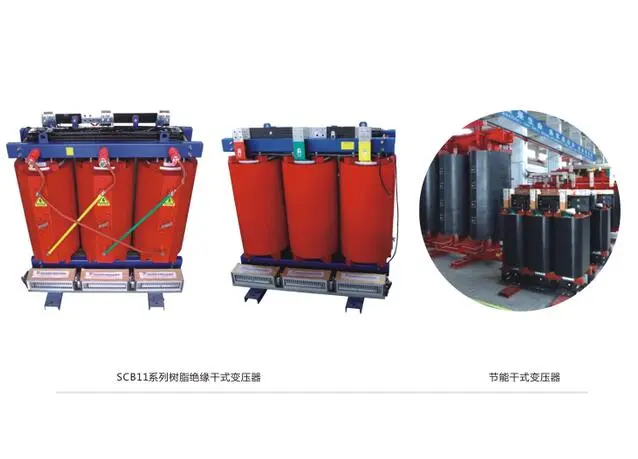
If it is necessary to reduce the cost by reducing the diameter of the core by increasing the number of winding turns, in order to keep the impedance unchanged, it is necessary to make the entire 1600kVA Cast Resin Transformer more “thin and tall”.
For transformers with copper windings, we usually reduce costs by making the transformer more “chunky” because copper is more expensive than silicon steel sheets.
For transformers with aluminum windings, we usually use the method of making the transformer more “thin and tall” to reduce costs, because aluminum is relatively cheap.
The no-load characteristics of the 1600kVA Cast Resin Transformer is one of its main performance parameters, including no-load current and no-load loss, which are mainly determined by the core structure of the transformer, the grade of silicon steel sheet and the magnetic flux density.
The no-load current of the 1600kVA Cast Resin Transformer generates a magnetic potential NI0 and a magnetic flux in the iron core, and the magnetic flux passes through the iron core, so there will be some losses in the iron core silicon steel sheet, that is, no-load loss.
Therefore, it can also be considered that the no-load loss is the loss generated by the iron core, which is mainly composed of hysteresis loss and eddy current loss.
No-load loss has nothing to do with the load, only the core magnetic density and the related insulation structure.
Therefore, if you consider reducing no-load loss, you should start with reducing the magnetic density of the core and adjusting the insulation structure.
The load loss of the transformer is mainly composed of the resistance loss of the conductor in the high and low voltage coils, the additional loss, the lead loss and the stray loss caused by the pull plate and the clip.
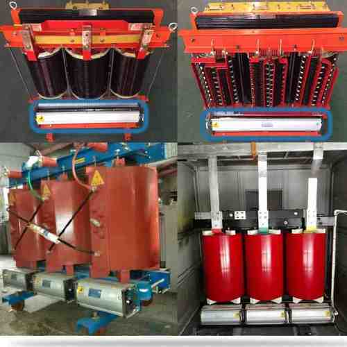
The main material of the transformer core is silicon steel sheet, which is one of the main materials of the transforme
The main material of the transformer’s high and low voltage windings is copper wire.
Three types of copper wires are mainly used in the series products studied in this paper, namely enameled copper flat wire, enameled copper round wire and copper foil. Since this design only uses enameled flat copper wire and copper foil, the calculation method of enameled flat copper wire and copper foil is given below.
The phase/line voltage and phase/line current are the basic parameters in the electromagnetic calculation of the transformer, and are also the basis for the calculation of other parameters. The phase current and phase voltage on the high and low voltage sides directly affect the performance of the transformer, as well as the overall design process of the transformer.
Because in delta connection, phase current = line current, so Ua=Uh=10000V
The number of turns of the coil affects the magnetic flux density of the iron core, and at the same time, the magnetic flux density of the iron core determines the loss level of the iron core.
Therefore, under the premise of meeting the magnetic density requirements of the transformer, the change of the number of coil turns will also cause the change of the core diameter and no-load loss.
Download Resource

Table of Contents Selecting the right pad-mounted transformer requires careful consideration of several critical
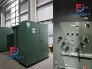
The primary function of the pad mounted transformer is to serve as a critical distribution
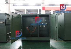
A pad mounted transformer operates through electromagnetic induction, serving as a crucial distribution component that
After filling in the contact information, you can download the PDF.