
How to Choose Pad Mounted Transformer?
Table of Contents Selecting the right pad-mounted transformer requires careful consideration of several critical
ELECTRIC, WITH AN EDGE
Canada’s rivers and lakes are abundant enough to cover the entire country to a depth of 2 m. More than 1,000 dams and water supply systems have been built. A review of some of the major Canadian water projects, including dams, demonstrates the significant achievements of Canadian engineers in exploiting the country’s water resources under challenging conditions.
Looking for a reliable and high-performance transformer for your water project? Look no further than Daelim Belefic. Our transformers are designed to meet the demands of water projects, providing safe and reliable power to ensure the smooth operation of your systems.
Our transformers are manufactured to the highest standards, including compliance with international standards such as IEC 60076, GB 6451, AS NZS 60076, CSAC88-16, ANSI/IEEE C57.12.00, and GOST R 52719. This ensures that our transformers meet minimum performance and quality requirements, as well as specific requirements for different regions and countries.
In addition, our transformers are designed to withstand harsh environmental conditions, ensuring reliable performance even in extreme temperatures, humidity, and other challenging environments. This makes our transformers ideal for water projects, where reliability is essential to ensure the safe and efficient operation of systems such as water treatment plants, irrigation systems, and pumping stations.
At Daelim Belefic, we understand that downtime can be costly for water projects, leading to delays, lost revenue, and potential safety hazards. That’s why our transformers are designed to deliver maximum uptime, with features such as temperature monitoring, fault detection, and automatic shutdown in the event of a problem.
In addition, our transformers are designed for ease of maintenance, with features such as removable covers and easy access to components. This ensures that maintenance and repairs can be carried out quickly and easily, minimizing downtime and ensuring the smooth operation of your water project.
So if you’re looking for a reliable and high-performance transformer for your water project, choose Daelim Belefic. Our commitment to safety, reliability, and quality ensures that our transformers will meet your needs and exceed your expectations. Contact us today to learn more.
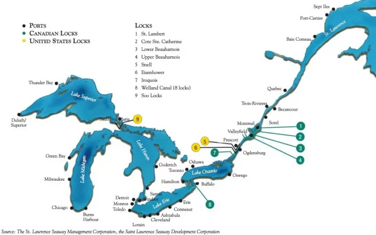
The St. Lawrence Seaway is an integrated waterway system of channels, canals and locks that connects the Atlantic Ocean to the Great Lakes. It is one of the most important transport routes in the world. The waterway runs through 2 provinces and 8 states in Canada and the United States, with a total length of 3,790 km and a depth of 8.2 m. It is home to 1/4 of the population of North America and is connected by 40 provincial and interstate highways and 30 railways to the ports and terminals of the waterway. The St. Lawrence Seaway can be divided into 4 sections.
(1) The Lachine section, which is 50 km long, is the gateway to the St. Lawrence Seaway and begins approximately 1 km east of the Jacques Cartier Bridge in Montreal. Its main purpose is to bypass the rapids of Lachine, the first major natural obstacle along the St. Lawrence Seaway. The route is much longer when taken along the south coast rather than the north coast, mainly to bypass the congested Port of Montreal and the St. Mary’s Current. In addition, the south coast has less impact on the shoreline. It also allows for better integration with existing transport facilities. The two stages of locks, the St. Lambert and St. Catherine locks, have a lift height of 13 m.
(2) The Boianouart section is 74 km long and runs from the end of Lake St. Louis in Quebec to Cornwall in Ontario. This section has two main uses: shipping and power generation. There are two stages of locks with a lift height of 12 m each: the upper and lower Boianuil locks take the waterway through the Cascades, Split Rock, Cedar and Coteau Rapids between Lake St. Louis and Lake St. Francis. The second most important use is the construction of the Boianoua Power Station, which takes advantage of the 24 m drop. The power station is supplied by a series of dams that regulate the flow of the section.
(3) International section
This section, which is also used for navigation and power generation, is jointly managed by the United States and Canada and is 71 km long, consisting of a series of dams (Ronsort and Iroquois), power stations, locks (Iroquois, Eisenhower and Snell), channels and embankments, forming numerous generating cells. This section has a lift height of 28m and can be subdivided into the International Rapids section and the Thousand Islands section.
(4) Great Lakes Waterway
This section consists of a series of channels and locks connecting the Great Lakes. The Welland Canal is the most important canal, with eight locks built around Niagara Falls to overcome the 99 m difference in water level between Lake Ontario and Lake Erie. locks 1 to 7 are lift locks with an average lift height of 14.2 m. lock 8 is a restraint lock, one of the longest locks in the world, and is used to finally regulate the water level of Lake Erie.
The channels connecting Lake Erie to Lake Huron, Lake Huron to Lake Michigan and Lake Huron to Lake Superior have a lift height of 6 m and are also part of the waterway.
1.1 Waterway construction
Between 1954 and 1959, more than 22,000 people took part in the construction of the St Lawrence Seaway. A total of US$470 million was invested in earthworks, dam construction, concrete pouring and water diversions (Canada and the United States paid US$336.2 million and US$133.8 million respectively).
It was a huge task, with 192.5 million m3 of soil transported, 5.7 million m3 of concrete poured, 72 km of embankment built and 110 km of navigation channel excavated. The existing 4.3 m deep channel and 30 locks were replaced by an 8.3 m deep channel and 15 locks. Each lock has a length of 233.5m, a width of 24.4m and a depth of 9.1m.
The construction of the St. Lawrence Seaway in the 1950s increased the depth of the Atlantic-Great Lakes route from 4.3 m to 8.3 m while the number of locks was reduced from 30 to 15. For the first time, the waterway was able to accommodate vessels of over 35,000 tons, 233.3 m long and 23.2 m wide.
As the 50th anniversary of the St. Lawrence Seaway approaches, the shipping sector is pressing for the dredging and widening of the channel and the expansion of the locks to accommodate oversized ships.
In addition, there are plans to use icebreakers to make the waterway navigable all year round. The St. Lawrence River Group has also expressed concern about further expansion of the St. Lawrence Seaway, citing the significant environmental impacts of blasting, dredging and additional uses as.
(1) Damage to sensitive habitats and shoreline features due to ice erosion.
(2) Adverse economic impacts on regional tourism.
(3) Increased difficulty in managing water levels.
(4) Damage to fish and wildlife populations
(5) increased levels of chemical poisoning of fish
(6) Potential for uncontrollable crude oil and chemical spills.
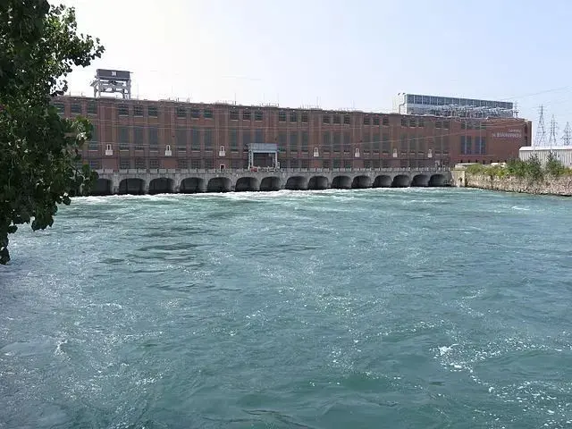
The Beau-Anouillet hydroelectric power station is currently the largest hydroelectric power station on the St. Lawrence Seaway located 40 km west of Montreal. The power station utilises the available head between Lake St. Francis and Lake St. Louis.
This run-of-river power station has a capacity utilisation rate of more than 85%. The needs and interests of neighbouring countries, the St. Lawrence Seaway and the Port of Montreal must be taken into account.
The average flow rate of the section of the river in which the power station is located is approximately 8,000 m3/s. Between 1930 and 1961, the power station building was built in three phases over a length of nearly 1,000 m. The plant was built in 1930 and 1961. The plant houses 36 generating units (and two back-up units) with a total installed capacity of 1,656,000 kW and a head of 24 m.
The Boianuil power station is one of the five power stations with the largest installed capacity of the Hydro-Quebec. In the 1970s, the oldest 14 generators were rewound and a few improvements were made to the power station equipment.
The power station is listed by the Historic Sites Protection Board of Canada as a National Historic Site.
The Maniquagan River is located in northern Quebec and flows in a north-south direction for 563 km through the Plateau region. It eventually joins the St. Lawrence River, northeast of Montreal. The Maniquagan River basin covers an area of 45,600 km2.
Its integrated hydroelectric development terrace is located 210 km north of the city of Békomo and comprises five power stations with a total installed capacity of 4,974,000 kW, from upstream to downstream: Maniquagan-5 (Daniel Johnson Dam, Manic5 and Manic5 PA), Maniquagan-3, Maniquagan-2 and Maniquagan-2. Maniquagan-2 and Maniquagan-1.
Construction of the Manic 5 power station began in 1959 and was completed in 1971. The power station was equipped with eight 16.15 million kW mixed flow units (141.8 m head) with a total installed capacity of 1.528 million kW, which were commissioned between 1969 and 1971.
At the end of the 1970s, an optimisation study of the Maniquagan hydroelectric complex showed that the maximum capacity of the terrace could be increased by approximately 2.1 million kW by replacing the existing runners and building a new power station at the already developed dam site. Construction began and was completed in 1989 with the installation of four mixed-flow units (145 m head).
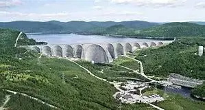
The Maniquagan-5 development comprises the Daniel Johnson dam, the Manic5 class and the Manic5 PA class power station. The dam forms a reservoir 200 km long, with a reservoir area of 1 942 km2 and a capacity of 138.8 billion m3. Five large rivers feed into the reservoir, making it the largest of the Maniquagan integrated development stages.
This is a 242 m high earth and rock dam with a crest length of 792 m and a width of 33.8 m. There is also an underground plant with four units and a total installed capacity of 1,792,000 kW, which is owned and operated by the British Columbia Hydroelectric Authority. The project is located on the Columbia River. It is proposed to add two new generating units in the future.
The watershed is mainly influenced by marine air masses and climatic systems moving eastward across the watershed, with snow forming in winter and runoff mainly from snowmelt. runoff from June to July accounts for approximately 50% of the annual runoff. Rainfall makes a small contribution to annual runoff, but can form flood peaks, particularly in spring and autumn.
The Kimbaskit Reservoir is 216 km long and has a maximum effective capacity of 14.8 billion m3. 42,500 hm2 of reservoir area.
The Mecca Dam, the tallest dam in Canada, was commissioned in 1973 and the underground plant was completed in 1977. The dam is a zoned rockfill dam with a moraine soil core wall, a sand and gravel shell and a rockfill outer shell. The dam is built on mica schist and granite gneiss with some pegmatite and white marble.
The underground plant is located on the right bank and is equipped with four units and two standby units, with a rated capacity of 435,000 kW.
The generators are of the vertical shaft umbrella type with the following specifications: 456 MVA, 0.95 PF, three-phase, 60 Hz, 16 kV. Each generator is equipped with three single-phase transformers, which are placed in the cavernous chamber downstream of the plant, each with the rated parameters 152.2 MVA, 16 kV-512 kV (16 kV for triangular connection, 512 kV for star connection). 512 kV).
Six 5.25 m wide, 6.70 m high helical inlet gates are installed and connected to the concrete/steel lined underground steel pipes with an average length of 270 m and a diameter of 6.8 to 5.9 m, which are arranged on the right shoulder of the dam.
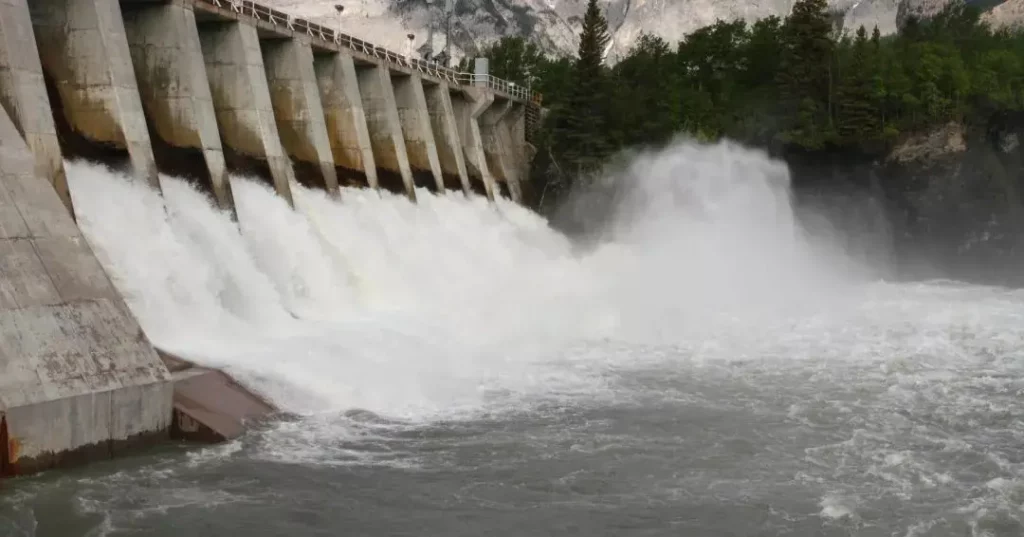
The spillway is located on the left shoulder of the dam and is equipped with three 12.2 m wide, 12.8 m high arc gates at the top of the counter-arc overflow weir, which is connected to a long steep chute and a pick-up nose under the weir. The total flow rate of the spillway is 4,250 m3/s at the highest flood level of 757.4 m and 3,110 m3/s at the highest normal storage level of 754.4 m.
Diversion Tunnel No. 2 was converted at a later stage into a drainage bottom hole with a double concrete plug and a chamber energy dissipator to facilitate control of the reservoir during storage. In the 1980s, the chamber was sealed with concrete and the valves used to operate the chamber were discontinued. The existing spillway facilities are located in bedrock adjacent to the steep chute of the spillway.
The reinforced concrete intake tower is approximately 76 m high, with two 3.1 m wide, 5.5 m high, sheet steel lined rectangular pipes at the base of the intake tower, each with a separate control gate and ventilation shaft, located just above the No. 1 diversion tunnel. The flow of the pipes flows through a 9.1 m diameter inclined circular tunnel into Diversion Tunnel No. 1, which has a diversion nose at the gradient section.
The volume of work for the flood relief building is as follows: 6.4 million m3 of excavation, 32.8 million m3 of filling, 37.9 million m3 of concrete, 14,300 t of reinforcement, 730 t of structural steel and 2,460 t of steel pipes.
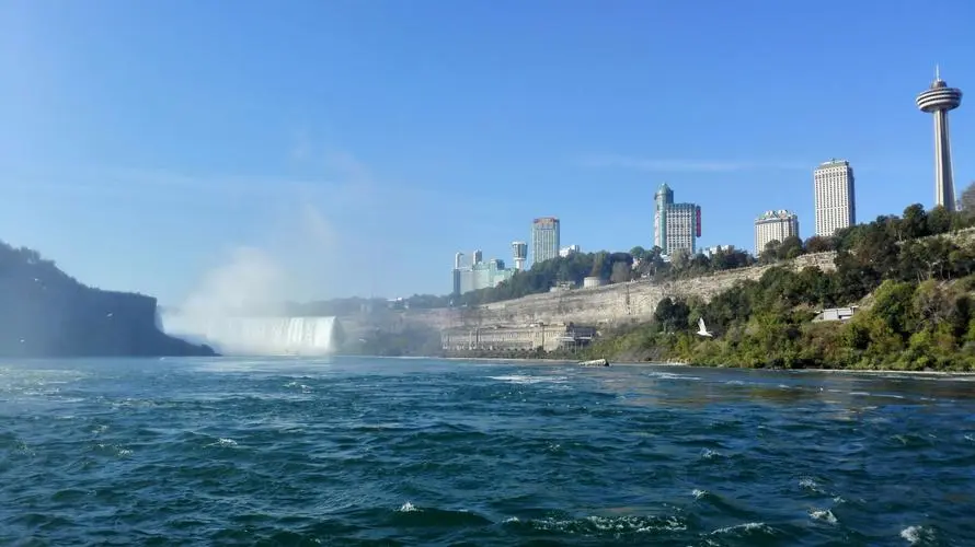
The Niagara River is one of the most hydropower-rich rivers in the world. The magnificent waterfall scenery from Lake Erie to Lake Ontario attracts a large number of visitors every year. A short stretch of the river, 56 km long, has a drop of 99 m, with most of the spectacular rapids being concentrated in a 13 km long section of waterfalls and rapids.
The three main power stations on the Canadian side of the river are the Sir Adam Beck 1 and 2 power stations and the nearby pumped storage power station. Since 1958, Sir Adam Beck 2 has been one of Ontario Power Generation’s largest and most reliable hydroelectric facilities.
(1) Plant
The plant was 170.6 m long and 41 m wide, constructed of reinforced concrete and steel frames, nine storeys high, with 10 generating units installed in the plant, and cost $76 million to build. construction began in May 1917 and water was introduced into the diversion channel on December 24, 1921. The works were originally called the Queenstown-Chippewa Power Station.
(2) Forebay and headworks
There are 2 inlets into the forebay with an inlet diffusion angle of 10°. The diffuser section is a wedge-shaped structure, 67.3 m long and 11.3 m wide at the downstream end, with upright smooth side walls, 8.5 m above the bottom of the forebay.
The 152 m long filter chamber has three openings to the pressure steel pipe, each with a maintenance gate and an interceptor. There are 10 pressure steel pipes, 116.8 m long and 4.9 m in diameter, with a Johnson valve at the end of each pipe, just in front of the snail casing, serving as the first gate.
(3) Inlet
The entire inlet structure is approximately 335 m long and consists of an inlet with a navigable gate, a retaining wall section and an inlet.
The conventional or surface inlet consists of a concrete dam with 15 orifices, each 5.5 m wide and normally submerged to a depth of 2.4 m. With the lift gate, the depth of submergence can reach any depth up to a maximum depth of 10.7 m.
The submerged inlet has six collector or diversion pipes, each approximately 30.5 m long, and water enters these pipes on the upstream side through the gate slots for a total length of 152.4 m. These pipes are controlled by gates and the inlet flow rate is aligned with the flow rate of the Welland section.
The design inflow rate through each gate slot is 70.8 m3/s (along the axis of the pipe). At a flow rate of 70.8 m3/s, the total head loss from each collector pipe to the end of its diffuser section is only 0.09 m.
If there are no ice floes in the river, the gates of the surface and flooded intakes are open all year round and the channel is also open. As a result, the flow velocity through the inlet from any location is very low, so that the head loss is normally negligible under normal circumstances.
The first unit was put into trial operation on 25 December 1921 and, one month later, into full operation. The tenth unit was commissioned in July 1930.
Each unit has its own transformer bank and transmission circuit. The individual generators weigh approximately 1,044 t and the individual transformers weigh 100 t. The rated output of the 10 generators at a net head of 100 m is 500 MVA.
(1) Plant
The gate operating machinery is a 25 t mobile portal crane. The generators are of the fully enclosed water-cooled type; each has a non-continuous damping winding and is equipped with a directly connected exciter and a static voltage regulator.
(2) Forepond and headworks
Not far from the headworks, there is a 30.5 m wide, 213.3 m long interconnecting canal connecting the former pond with the former pond of Sir Adam Beck Power Station No. 1 to the immediate north.
The headworks are 266.7 m long and are equipped with a conventional design barrier and electronically controlled fixed wheel gates (2 gates per pressure pipe). In case of emergency, the gates can be closed by remote control from the plant. As there are no valves at the downstream end of the pressure tubes as in the case of Sir Adam Beck 1, these gates are the only control element for the pressure tubes.
(3) Tunnel inlets
The tunnel inlets at Sir Adam Beck 2 Power Station are designed for the following purposes.
① Minimal disturbance to the natural flow regime of the water.
② to control the maximum catchment area.
(iii) to keep the inlet flow velocity to a minimum
(iv) to collect water from the bottom of the river to eliminate the effects of surface icing.
For this reason, two catchment pipes were installed on the Niagara River bank approximately 0.4 km from the inlet of the Sir Adam Beck No. 1 power station.
The two square section collectors run parallel to the river and increase in cross-sectional area from 6 m2 at the upstream end to 14 m2 at the downstream end. 200 m long each collector has 30 intakes on one side of the river, decreasing in area from upstream to downstream, the top of each intake being 1.8 to 2.4 m lower than the lowest river level at that point.
A control gate, 18 m high and 14 m wide, is located at the 14 m2 section of the collector, behind which the section changes from a square to a circular shape, with an inner diameter of 14 m and a length of 113 m. It is connected to a tunnel of the same diameter. At the beginning of the tunnel there is a 30° downward slope until the tunnel lies approximately 100 m below ground level and 85 m below the river surface.
There is a slow downward slope until the tunnel reaches its maximum depth of 90 m (at the traffic tunnel No. 5), after which the tunnel gradually rises for nearly 8 km, and then rises sharply at the exit. The remaining 3.6 km section to the former pool is located in a fairly open suburban area, where the channel needs to be dug significantly less deeply than the upstream section.
The excavation of the two tunnels, located approximately 75 m apart, began with five shafts located between the tunnels, from which the cross-guide pits were excavated and the tunnels and guide tunnels were dug from each side of the cross-guide pits until they joined the guide tunnels dug from the next cross-guide pit. This was followed by a stepped excavation and lining of the tunnel.
As the diameter of the excavation was approximately 15 m, the final diameter of the circular section of the tunnel was approximately 13.7 m. The tunnel lining was therefore approximately 0.6 m thick. As the excavation progressed, steel arches were installed at 1.2 m intervals to support the rock and the steel jacket. Before pouring the concrete into the steel arches, the steel sleeves used for the installation are removed.
The concrete for the tunnel lining is first placed at the inverted arch or bottom at 60° of the corresponding circumference, followed by the side walls and the top arch after 15 to 27 m of steel formwork. Each section of formwork is retained for around 12 h until the concrete is strong enough to bear its own weight.
The formwork is then moved forward in preparation for the next round of pouring. To avoid uneven joints between adjacent cast sections, every effort is made to maintain precise positioning of the formwork and to smooth out the joints to prevent turbulence. The tunnel construction required 3 440 700 m3 of excavation and 764 600 m3 of concrete to be poured.
(4) The tunnel after completion of the tunnel drainage section, from the inlet to the outlet, is an inverted siphon tunnel, with the tunnel reaching its lowest elevation near the traffic shaft No. 5. A drainage station was built in the cross guide pit between the tunnels in this shaft to drain the tunnels for inspection or maintenance. Eight submersible pumps, each 6.8 m high and 45.7 cm in diameter, were installed and connected directly to a 450 hp fully enclosed oil-immersed submersible motor, which was controlled from the surface. As a result, the pumps can still operate even if the entire drainage station is flooded. At maximum efficiency and a head of 104 m, each pump has a rated flow rate of 15 000 L/min. The drainage station can drain any of the tunnels within 7 d.
(5) Completion
The estimated construction cost in 1951 was $157 million. 1956 saw the completion of the above-ground reservoir by Ontario Hydro. The rock excavated for the diversion channel was used to reinforce the reservoir banks, which were approximately 3.2 km long and 0.8 km wide. Six 30 MW reversible turbines were used to pump the water to the reservoir at night. During the day, water is released from the reservoir to generate electricity. To ensure that the year-round water supply is not interrupted by the freezing of the river, Ontario Hydro circled an area of the Upper Niagara River at the intake and ran two 152 m long pipes underwater. Each pipe was capable of supplying water to the tunnels at a flow rate of 28,000 m3/min, while the two tunnels were capable of supplying water to the Sir Adam Beck No. 2 power station at a flow rate of 57,000 m3/min.
In March 1954, the Sir Adam Beck Niagara Power Station began generating electricity, with a total installed capacity of 1,224 MW from 16 units, and was the world’s largest power station at the time of commissioning, although it remained the world’s number one for only a short time.
Niagara Power Station provides 25% of all electricity used in New York State and Ontario. The Sir Adam Baker Power Station and the Robert Moses Power Station are known as the 2 largest hydroelectric power stations in North America.
As a possible site for a hydroelectric dam, Churchill Falls has the distinct advantage that the deficiencies of the area can be overcome, that rainfall and runoff patterns are reliably predicted and that extensive water storage is possible on the plateau. For hydropower development, the river’s natural drop of more than 300 m over a stretch of less than 32 km is perhaps the most significant feature.
After several years of planning, work began in July 1967 and testing of the distribution lines and the first two units began in November 1971, when the project was completed. The Twynfalls hydroelectric power station on the unnamed river, a tributary of the Churchill River, was built in the early 1960s with an installed capacity of 225 MW to supply electricity to the iron ore industry in western Labrador.
The hydroelectric power station was essential to the development of Churchill Falls, helping to develop the area and also providing the electricity needed during construction work.
The water from Churchill Falls Hydroelectric Power Station generated almost three times as much electricity as the same volume of water from Twyford Falls Hydroelectric Power Station, which was closed in July 1974 to divert water into Smallwood Reservoir.
The basic figures for the Churchill Falls hydroelectric power station are as follows.
Original rated capacity/MW | 5225 |
Rated capacity after 1985 upgrade/MW | 5428.5 |
Hydraulic turbine / unit | 11 |
Length of pressure steel pipe / m | 426.7 |
Main plant, length×width×height/m | 5428.5 |
Area/hm2 | 569800 |
Normal storage level/m | 473 |
Effective storage capacity/billion m | 289.7 |
Normal storage level/m | 479 |
Effective storage capacity/billion m | 28.4 |
Number of dykes | 88 |
Height of dike/m | 9~36 |
Total filling volume/million m | 32000 |
Total length of dike tops/km | 64.4 |
Three transmission lines from the Churchill Falls hydroelectric power station cross the Labrador area.
The main plant, excavated in the hard rock beneath the Labrador Plateau, is 296 m long, up to 25 m wide and 47 m high, and more than 11,000 rock anchors (5-6 m long reinforcement bars) were installed in the three main chambers to reinforce the walls and roof of the cavern.
The excavation of the plant was completed in 1970 and the first two units began transmitting electricity to Hydro-Québec on 6 December 1971, when the project was put into commercial operation.
From 1975 to 1991, the Churchill Falls hydroelectric power station generated 595 TW-h of electricity, equivalent to an average annual output of 35 TW-h. A total of 88 dykes enclose the reservoir, the longest being 6.1 km and the highest 36 m.
There are no dams associated with the hydroelectric power station and the water level is controlled by three spillways and three control structures. The intake is monitored and adjusted from a central control room at Churchill Falls.
The Lower Churchill development is planned to be located 200 km downstream of Churchill Falls and will add 2,264 MW to the grid. the Upper Churchill development is planned to be located within 1 km of the existing facility and will add 1,000 MW.
Download Resource
Table of Contents Selecting the right pad-mounted transformer requires careful consideration of several critical

The primary function of the pad mounted transformer is to serve as a critical distribution

A pad mounted transformer operates through electromagnetic induction, serving as a crucial distribution component that
After filling in the contact information, you can download the PDF.