
How to Choose Pad Mounted Transformer?
Table of Contents Selecting the right pad-mounted transformer requires careful consideration of several critical
ELECTRIC, WITH AN EDGE
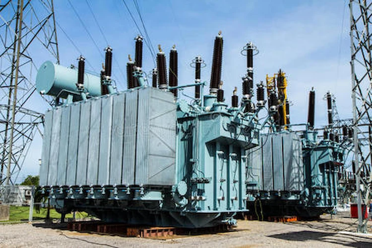
The 50mva transformer is a power transformer. Daelim has types of 50 mva transformers. Among them, 220kv, 110lv, 69kv low-loss series power transformers are exclusively developed by daelim. It has the characteristics of low loss, strong anti-surge protection ability and low partial discharge.
With more than 16 years of experience in designing and producing transformers, Daelim has provided professional transformer solutions to Canada, Mexico, Myanmar, Chile, Honduras, Australia, the United States and other countries. At the same time, the power transformers produced by Daelim have passed the certification of IEEE, CSA, SGS, CESI and other industry standards, providing a favorable guarantee for your power grid construction.
The 50 mva transformer is a 110kv power transformer with large capacity, low loss, low noise, strong short-circuit resistance and low partial discharge. The rated capacity of the 50 mva transformer is 6300~63000kva. The frequency is 50HZ/60HZ. The silicon sheet is used as the iron core material, the primary voltage is 110kv, and the secondary voltage is 10.5.
Partial discharge of 50 mva transformer: Apparent discharge under 1.5 times rated voltage is less than 80pC;
Noise of 50 mva transformer: 63MVA and below products are lower than 58dB(AN);
Power loss of 50 mva transformer: no-load loss is 30% lower than IEC standard;
Reliability of 50 mva transformer: all products in use have no damage and no oil leakage;
Short-circuit resistance of 50 mva transformer: SFZ11-50000/132 type successfully passed the short-circuit resistance test of the National Transformer Quality Supervision and Inspection Center, and passed the Dutch “KEMA” quality control system.
(1) The iron core of the 50 mva transformer adopts a pull-plate frame type clamping structure, full oblique joints, single-phase three-column type, and is composed of cold-rolled silicon steel sheets with low loss, grain orientation and high magnetic permeability.
(2) The iron core feet, clamps and pull plates of the 50 mva transformer have been optimized and calculated to ensure the mechanical strength of the product body under lifting, pressing, iron core clamping and short-circuit conditions.
(3) The iron core of the 50 mva transformer is provided with oil passages at appropriate positions to facilitate heat dissipation. Structural parts such as iron core pull plates and clips are made of non-magnetic steel materials or magnetic shielding to prevent local overheating caused by magnetic leakage.
(4) The clamp and iron core of the 50mva transformer are insulated from the oil tank. The grounding wire is led out through the grounding bushing on the top of the oil tank and is reliably grounded along the outer wall of the oil tank.
(1) In order to improve the winding gradient distribution and impulse potential, the series capacitance of the high-voltage head-end line of the 50mva transformer can be increased, that is, the high-voltage winding adopts an inner screen continuous structure.
(2) The low-voltage winding of the 50mva transformer adopts a U-shaped spiral structure, so that the direction of the current in the U-shaped low-voltage winding is just opposite, which can reduce the local overheating phenomenon of magnetic leakage of metal structures caused by low-voltage and large current.
(3) The high-voltage winding adopts graded insulation, and the neutral point is directly grounded. The low voltage winding is fully insulated. The main insulation and lead wire insulation structure adopts insulation molding and molding angle ring.
(4) All windings of transformer 50mva are wound with self-adhesive transposed wires with high conductivity to improve short-circuit strength, reduce skin effect and reduce eddy current loss.
(5) Transformer 50mva design of the winding oil flow distribution is carried out by using the OFFWF cooling method. In order to effectively reduce the average temperature rise and hot spot temperature rise of the windings, axial oil passages are arranged in the low-voltage and high-voltage windings to dissipate heat. At the same time, the oil circuit is reasonably designed according to the results of the temperature rise calculation software, and the winding temperature and oil temperature are controlled to meet the standard requirements or user requirements.
(1) In order to ensure the insulation strength, the electric field at the winding end and the main insulation are simulated and calculated. The main insulation adopts the commonly used thin paper tube with small oil gap structure.
(2) In order to improve the electrode shape of the iron core, ground screens are placed on the core column, side column and upper and lower yokes of the transformer.
(3) Densification measures are adopted for the cushion block, the inner diameter side of the low-voltage winding adopts a cardboard tube as the skeleton, the winding end adopts a high-strength pressure plate structure, and the body adopts an integral sleeve structure.
(1) A molded insulating part is placed at the tail end of the high-voltage lead, and the connection is shielded by a copper tube, and the lead wire adopts a direct structure.
(2) The low-voltage lead wire adopts a copper bar structure to ensure the current carrying capacity and strength of the lead wire.
(1) The fuel tank is a bell-shaped structure, the top of the fuel tank is a micro-arch inclined plane, and the reinforced iron of the fuel tank wall adopts a groove-type reinforced iron. Use simulation software to check the vacuum strength, positive pressure strength and transportation strength of the fuel tank to ensure the overall mechanical strength of the fuel tank.
(2) The upper and lower parts of the fuel tank are sealed and welded structures. The fuel tank and all steel components shall be well sandblasted and derusted, and rust, oxide scale and welding slag shall be removed before painting.
(3) In order to reduce stray losses and solve the problem of local overheating of the tank wall, a magnetic shield is installed on the inner wall of the fuel tank to reduce magnetic flux leakage. At the same time, in the lead-out part of the low-voltage bushing, non-magnetic materials are used to prevent local heating.
1. Double winding non-excitation voltage regulating transformer
High voltage side: 110kV, 121kV; low voltage side: 6.3kV, 6.6kV, 10.5kV, 11kV.
2. Three-winding non-excitation voltage regulating transformer
High voltage side: 110kV, 121kV; medium voltage side: 35kV, 38.5kV; low voltage side: 6.3kV, 6.6kV, 10.5kV, 11kV.
3. Double winding low voltage is 35kV non-excitation voltage regulating transformer
High voltage side: 110kV, 121kV; low voltage side: 35kV, 38.5kV.
4. Double winding on-load voltage regulating transformer
High voltage side: 110kV; low voltage side: 6.3kV, 6.6kV, 10.5kV, 11kV.
5. Three-winding on-load voltage regulating transformer
High voltage side: 110kV; medium voltage side: 38.5kV; low voltage side: 6.3kV, 6.6kV, 10.5kV, 11kV.
No-load loss is an important control parameter for a 50 mva transformer, and its value has nothing to do with the transformer load.
The factors that affect the no-load loss of 50mva transformers mainly include iron core structure, processing technology, material properties of silicon steel sheets, etc. In order to reduce the no-load loss of 50mva transformers, it is best to use silicon steel sheet materials with low unit loss, while improving its structure and manufacturing. craftsmanship level.
However, relying solely on the use of low-energy-consumption materials will increase the manufacturing cost of the iron core. By optimizing the structural form and manufacturing process level, it can not only save the material cost, but also achieve a better effect of reducing the no-load loss of the 50mva transformer.
In practice, the no-load loss of power transformers is reduced mainly by improving the structure of the iron core, optimizing the overlapping method of the iron core, adjusting the overlapping width, and changing the width of the iron core.
The hysteresis loss and eddy current loss of the 50mva transformer core are mainly determined by the silicon steel sheet manufacturer, and the additional loss of the transformer core is determined by the transformer manufacturer. Therefore, the 50mva transformer manufacturer and manufacturer are the main bodies to control the no-load loss of the transformer.
The overlapping width of the transverse yoke sheet and the core column sheet at the corner of the transformer 50mva lamination sheet has a certain influence on the no-load loss of the transformer. also bigger.
Combined with the test results, when the overlap area increases by 1%, the no-load loss at the joint angle of 45° will increase by 0.3%. Therefore, the mechanical strength and no-load loss must be met on the basis of the mechanical strength. To achieve the determination of the optimal overlap area.
To this end, a scheme to adjust the overlap area of the transformer 50mva iron core lamination is proposed, that is, to reduce the area of the triangular cavity in the middle of the iron core, and to reduce the magnetic flux density at the triangular cavity, and the overlap width of the side yoke is 47% of the core column section. %, the lap width of the main yoke is 53% of the core column section, which can not only ensure the strength of the iron core, but also improve the magnetic flux distribution of the iron core, control the deviation of the magnetic flux, and reduce the no-load loss.
From the perspective of the proportion of the outgoing angle of the iron core of the type of 50 mva transformer in the width of the core column, the carrying capacity of the iron core at the triangular cavity is improved after the outgoing angle is improved, even if the magnetic flux at the corner of the iron core lamination deviates from the silicon steel sheet rolling The area of the control direction area is reduced, which is beneficial to the uniform distribution of the magnetic flux of the iron core.
The reduction of the exit angle also reduces the deviation of the magnetic field line from the rolling direction of the silicon steel sheet, reduces the resistance work, and reduces the additional loss of the transformer core. The effect is more obvious.
When stacking 50mva transformer cores, 1~3 laminations are mainly placed on each layer, and the more the number of laminations, the larger the cross-sectional area of the air gap at the seam, and the greater the degree of distortion of the magnetic flux density at the seam. big. After the magnetic flux density is distorted, the magnetic flux density of the silicon steel sheet at the joint increases and the no-load loss increases.
According to this process, the distortion of the magnetic flux density at the seam caused by the one-on-one stack method is the smallest, and the no-load loss is also the smallest. Large-capacity iron cores are not suitable, but will increase no-load loss due to improper insertion, so large-capacity iron cores are usually stacked with two pieces.
Hybrid lamination is a new method of iron core lamination to reduce the no-load loss of the iron core and save the lamination time and yoke insertion time, that is, one piece for the 1/3 part of the total thickness of the iron core, and two pieces for the outer 1/3 part. The outermost 1/3 part is stacked with three pieces, which does not increase the total stacking workload, and can effectively reduce the no-load loss and no-load current of the transformer 50mva core.
The magnetic flux density distribution in the 50mva transformer core is not uniform, and the magnetic flux density in the middle part is usually lower than the rated value, and the external magnetic flux density is higher than the rated value. This also provides an idea for reducing the no-load loss, that is, by adjusting the stacking of the iron core, the magnetic flux density of each part of the iron core tends to be uniformly distributed.
The magnetic flux density in the middle part of the iron core is low, so one piece is stacked to increase the magnetic flux density, while the outer magnetic flux density of the iron core is high, three pieces are stacked to reduce the magnetic flux density.
The magnetic permeability of the magnetic steel sheet is larger than that of the air, so the magnetic flux at the seam will enter the adjacent laminations directly through the iron core, and will pass through the air gap when the magnetic flux of the adjacent laminations is saturated, in order to minimize the no-load Loss, the lamination seams should be staggered in a stepped arrangement.
According to the test, with the increase of the seam series of the 50mva transformer iron core, the local loss in the area tends to decrease, but the shearing of silicon steel sheets, the man-hours for iron core stacking, and the difficulty of lamination processing increase accordingly. In the tertiary seam form, the magnetic properties can be significantly improved with a slight increase in process complexity by strengthening the rational choice of the sheet type and using only one type of sheet in the stem.
Therefore, the use of three-stage seam form is ideal to improve the practice of staggered seam core. The test results show that when the cross section of the core column remains unchanged, the no-load loss of the three-level joint form is reduced by 9% to 10% compared with the staggered joint form. The construction difficulty of cutting silicon steel sheets and stacking iron cores is slightly increased, but the effect of reducing no-load loss is more significant.
If the five-level seam is adopted, the cross-sectional area of the seam will be significantly increased, the magnetic flux density at the seam will be significantly reduced, and the no-load loss will be reduced accordingly. In addition, the five-level joint form also reduces the area of the area where the magnetic flux deviates from the gadolinium direction of the silicon steel sheet at the corner, which in turn leads to a reduction in the number of magnetic lines of force deviating from the gadolinium direction of the silicon steel sheet, and the additional loss of the iron core is greatly reduced.
However, in the form of five-level joints, the construction difficulty and process complexity of shearing silicon steel sheets and stacking iron cores will increase significantly. Considering the construction difficulty, process complexity and no-load loss reduction, it is recommended to use three-level joints. form.
Download Resource
Table of Contents Selecting the right pad-mounted transformer requires careful consideration of several critical

The primary function of the pad mounted transformer is to serve as a critical distribution

A pad mounted transformer operates through electromagnetic induction, serving as a crucial distribution component that
After filling in the contact information, you can download the PDF.