
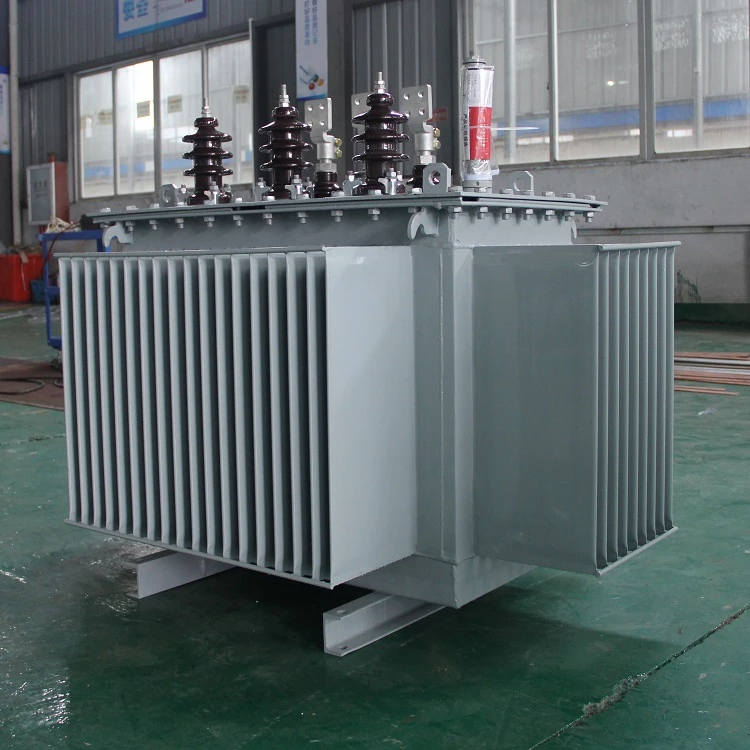
How to Choose Pad Mounted Transformer?
Table of Contents Selecting the right pad-mounted transformer requires careful consideration of several critical
ELECTRIC, WITH AN EDGE
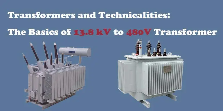
Low Voltage (480V) transformers are vastly different from medium voltage (13.8 Kv) transformers in every regard. The 13.8 kV to 480V transformer type can help the electric power distribution system by transforming voltages.
Indeed, a 13.8kV to 480v transformer’s voltage and current flow in the other direction. For the procedure to be complete, the voltage is raised and the amperage is reduced.
Transforms high-voltage power into low-voltage power and uses a lot more electricity as a result. A typical transformer voltage range is 2,400 to 69,000 volts, and this transformer is no exception.
The rectifier in a low-voltage transformer helps convert the transformer’s output into RFI and DC current. Because of the wide range of configuration options provided by this voltage transformer,
Using two sets of electric windings to transport current, this type of transformer transforms electrical energy.
One (1) 1000-KVA outdoor FR3-Filled, 13.8 Kv Delta, 60-KV BIL primary transformer with 2, -2 Taps at 2.5 percent Steps is included in this package.
There will be an increase of 60 degrees Celsius, OA, 480V Delta, and a 30-kV BIL secondary in each Transformer.
Air Terminal Chamber Impedance at 5.75 percent with copper windings and HV porcelain with 2 hole spade wall-mounted bushings is also available as an option.
On the welded panel-type radiators of the Air Terminal Chambers, a low voltage (LV) integral copper 6-hole spade wall-mounted bushing is integrated within a hinged door with locking features.
The NEMA 4 control cabinet installation and testing includes an alarm contact dial thermometer, a liquid level gauge, a vacuum gauge, and a pressure relief mechanism.
The cost is one of the most important factors to consider. Engineers often employ 13.8 kV to 480 volts with a power output of at least 250 horsepower. Because of the high cost of MV drives, this transition point was bigger when using a VFD with a motor.
The current crossover point for 13.8kV to 480V is roughly 600 horsepower, as dependability and price have increased.
Most technicians are certified to work on low-voltage equipment, but they lack the experience and training to manage 13.8kV to 480V because of their lack of experience and training.
Medium voltage drives require a more qualified and experienced specialist to service them because of their high price and importance.
It is difficult to find these technicians because they require so much training and experience.
Equipment and the cabinet must be operational in order to operate the low-voltage drive.
Arc flashes are common in this area, however flashes are almost impossible with 13.8kV to 480V since you must de-energize them before working on them. The drive’s power will be switched off in the case of a significant grounding system failure.
LED indicators make it possible to lower the 13.8kV to 480V to 50V or less in 15 minutes.
A Kirk key interlock or an electronic interlock cut the incoming power are used to secure the doors of enclosures ranging in voltage from 13.8 KVA to 480 KVA.
A positive pressure system with filtered air and protection from the weather can keep 13.8kV to 480V for up to 20 years. If these parameters are not met, a person’s life expectancy can range from 3 to 7 years.
Today’s medium-voltage motors can last anywhere from 15 to 40 years, depending on how well they’re maintained.
Those numbers are based on the drive’s expected lifespan, which should be taken into consideration. There is a wide range of drives’ MTBF based on the specific application.
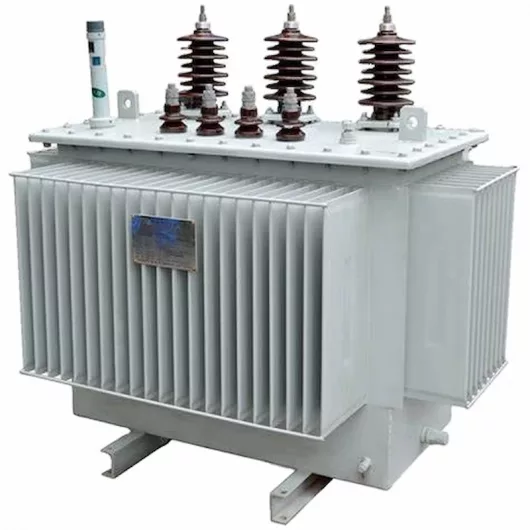
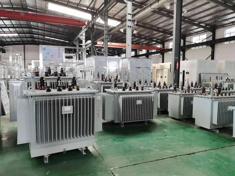
The most recent technology advancements are employed to produce power distribution transformers for a variety of applications in industry, commerce, education, and government.
These transformers are of the oil-cooled variety. An optimal level of efficiency requires a minimum amount of core and winding waste.
Thus, the service transformer provides the power distribution transformers in the electric power distribution system.
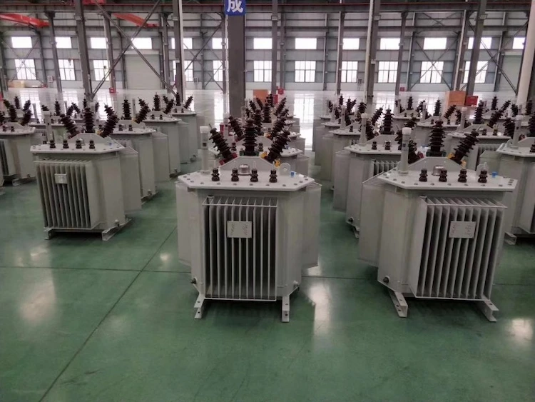
Distribution transformers were made practical by the development of a practical and efficient transformer; an efficient distribution transformer system.
Power distribution transformers are often classified as those with a power rating of less than 200 kVA, while some national standards allow for transformers with a power rating of up to 5000 kVA.
Due to their constant operation, even when not carrying a load, distribution transformers must minimize iron losses.
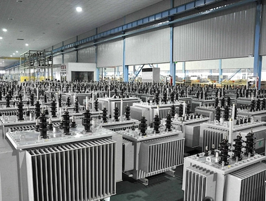
Reduced loads are part of their design, which helps them run as efficiently as possible. Transformers should have minimal voltage regulation for maximum efficacy.
As a result, they are designed to be leak-proof.
The following are a few uses for power distribution transformers:
First, it transforms high-voltage input to low-voltage output and can be found in both commercial and residential settings.
Second, the primary and secondary windings are isolated from each other by stepping down the input voltage.
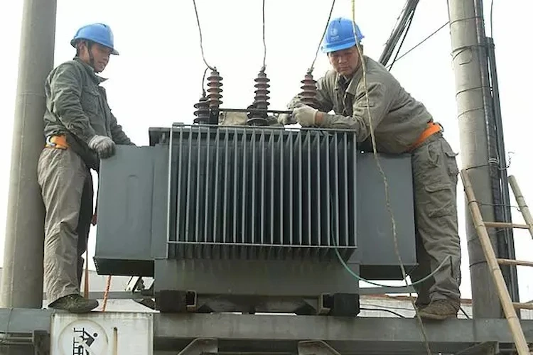
Then, remote areas produced by the power plants are supplied with energy via this transformer.
Lastly, power is typically distributed by a distribution transformer for use in both industrial and home applications below 33KV and 440V to 220V.
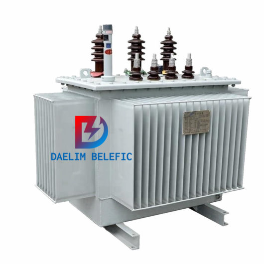
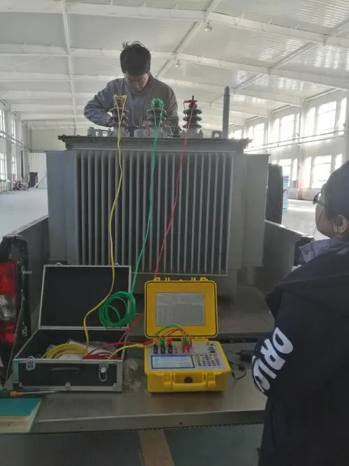
The working characteristics of transformers might vary from a small high-frequency audio transformer to a huge power transformer.
Any large transformer’s nameplate will list the following information, which may be broken down into eight categories: VA rating, cooling, transformer rating, frequency, voltage, phase, connections, and taps.
A conventional transformer can only supply a certain amount of current, and that current is limited by the transformer’s rated voltage.
For big power transformers, this VA rating is dependent on the ambient temperature or cooling.
If the VA rating is exceeded, the core and windings will overheat, resulting in damage.
The ambient temperature and cooling requirements for the VA rating is often specified on the nameplate.
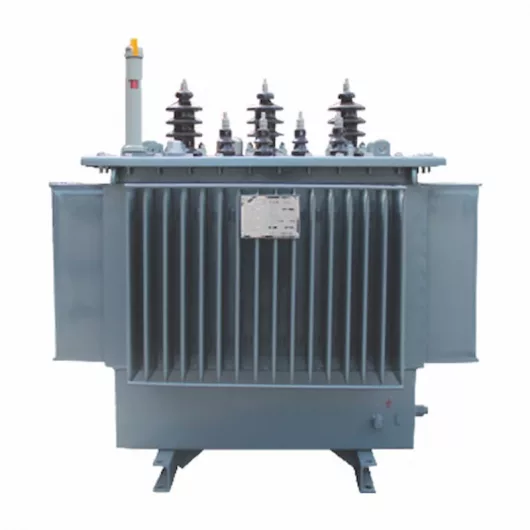
The sort of cooling required to supply the full rated load is included in oil-filled transformers. Insulated oil-filled transformers with cooling fans are commonly referred to as 1000kVA transformers.
In addition, 1000 KVA, 550 °C ORAN stands for the ability to provide 1000 KVA at 550°C with regular oil circulation, and this is what it can do.
For instance, ONAN stands for Oil Natural circulation with air naturally circulated cooling.
As such, this indicates that the transformer is equipped with an Oil Natural Air Forced cooling mechanism.
A slight increase in the rating could be achieved with the use of forced air-cooling.
In the automotive industry, OFAF stands for forced (pumped) oil circulation and forced (fan) air cooling radiators.
Thus, oil-forced cooling transformers (OFW) are used in big generating plants to cool the oil, which is then cooled by water.
In order to get the best flux connections and the lowest heating and power loss at a specific frequency, all transformers are built. An alternating magnetic field generates an induced voltage.
Due to a decrease in flux linkage efficiency, the core loses power at a higher than rated frequency.
Due to a decrease in flux connections at lower frequencies, winding losses are significant.
The voltage rating of the transformer is determined by the amount of winding insulation available.
Also commonly provided is the rated transient voltage that the transformer can withstand.
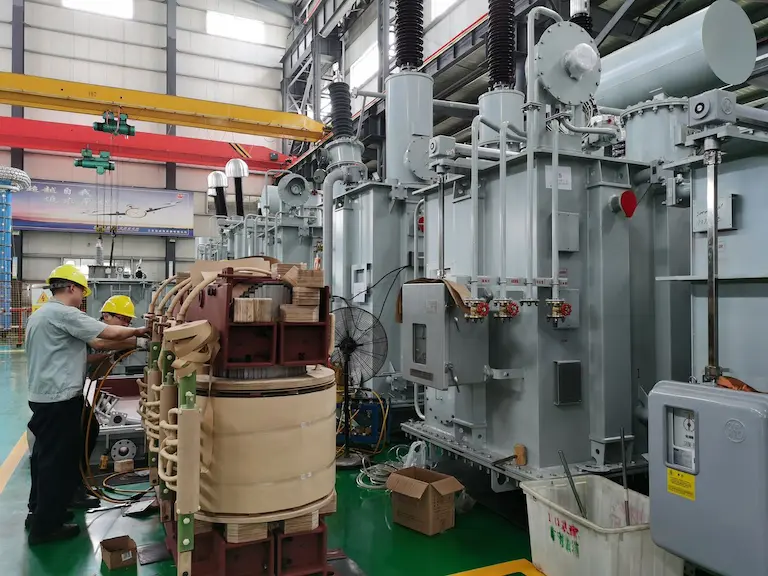
When installing huge three-phase power transformers, it is common practice to build three single-phase transformers and connect the input and output windings of each.
So, like with many transformers that convert the generating electricity from high current, isolated phase buses to higher voltage systems.
Single three-phase transformer construction is out of the question.
As with a transformer with two distinct windings, the autotransformer has the same ratios.
However, just a fraction of the single winding is used for the output.
Variable output voltages can be achieved with this arrangement.
Single-phase, three-phase star, three-phase delta, and zigzag are the most frequent transformer connections.
It is not necessary to explain this connection in this course, as it is utilized for grounding transformers.
Most three-phase transformers use either a star or a delta configuration for connecting the primary and secondary windings.
In a star winding, the star point is linked to the ground and thus ensures that all of the line terminals have equal and balanced voltages to the ground.
The transformer’s delta winding is not linked to the ground because it lacks a common point.
Transformers feature winding taps for fine-tuning the ratio of input to output turns and, as a result, the output voltage.
Therefore, transformers with infrequent output voltage variations benefit from the use of off-load taps.
There are several examples of how a generator need to be activated frequently as demand fluctuates throughout the day.
Depending on the demands of a power system, three-phase transformers are employed to increase and decrease voltage in three-phase circuits.
Moreover, you already know that three-phase systems are used to generate and transmit electricity.
In comparison to other polyphase systems, the three-phase system provides a number of distinct advantages. To raise or lower voltage in a three-phase circuit, three-phase transformers must be used.
Additionally, three-phase transformers are identical to three single-phase transformers in terms of their performance. Because of this, a three-phase transformer consumes less space and weighs less compared to three single phase ones.
There are no moving parts and two or more windings that are fixed in relation to each other in this electromagnetic energy conversion device, which is meant to transmit electric energy by electromagnetic induction between circuits or systems.
This might be a single three-phase transformer wound on one common magnetic core, or it can be an entire bank of triple-transformers for use in three-phase power systems.It’s better to use a three-phase transformer than a bank of single-phase transformers.
In terms of weight, size, and cost, a three-phase transformer wound on a common core is preferable to the bank of three single-phase transformers. With less external wiring and more efficiency than a bank of single-phase transformers, common core three-phase transformers are an ideal solution.
On the other hand, flexibility can be gained by using three single-phase transformers in a bank One or more transformers in the bank can be replaced by a larger or smaller kVA-rated transformer in the event of an imbalanced load.
Further, one of the bank’s transformers can be simply replaced, but the complete common core three-phase transformer must be replaced. The primary and secondary connections of the bank of single-phase transformers or the common core three-phase transformer can be connected in one of four ways.
Three-phase systems outperform single-phase ones in terms of performance as well as in terms of wiring.
In the case of electric motors, this is extremely true. Three-phase motors are more efficient than single-phase motors at the same horsepower rating. In light of the high electricity costs in New York City, this is a substantial benefit.
Consequently, for a given load and efficiency, three-phase motors require less volt-amperes from the grid.
Three-phase motors can assist reduce the costs associated with low power factors, which are included in some electricity rates.
Single-phase systems give pulsating power, which causes motors to vibrate more, whereas three-phase systems deliver a steady flow of power, which stabilizes the operation.
Adding to it, single-phase motors need auxiliary devices to get going because they can’t do it on their own. In contrast, three-phase motors are capable of starting and even reversing direction if two conductors are swapped.
Subsequently, there are many advantages to using a three-phase system instead of a single-phase one. Only one of the three conductors can be used to run a single-phase device on a three-phase power supply.
However, the inverse is not true: single-phase power cannot be used to run three-phase equipment.
It is possible to drive a three-phase motor with a single-phase power supply, but the motor’s mechanical power is significantly reduced and its service life is significantly limited.
Download Resource
Table of Contents Selecting the right pad-mounted transformer requires careful consideration of several critical

The primary function of the pad mounted transformer is to serve as a critical distribution

A pad mounted transformer operates through electromagnetic induction, serving as a crucial distribution component that
After filling in the contact information, you can download the PDF.