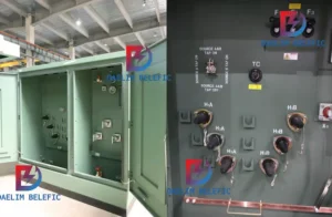
How to Choose Pad Mounted Transformer?
Table of Contents Selecting the right pad-mounted transformer requires careful consideration of several critical
ELECTRIC, WITH AN EDGE
As people become more and more concerned about environmental protection, more and more countries are making solar power a priority. This article describes how to build energy-efficient solar power plant, such as solar transformers, and how to choose the right cable cross-section.
Solar power plants are characterised by long power supply lines and widely distributed power generation equipment, high losses and large power generation capacity, as well as high potential for power saving. It is possible for a medium-sized solar power plant to reduce losses by several hundred thousand kWh per year.
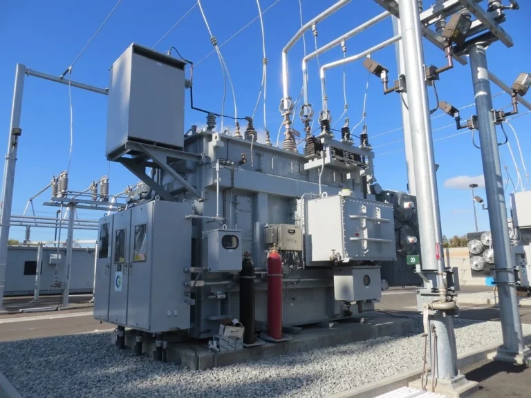
Daelim has many certifications from IEEE, IEC and IEEE, which means that the transformer supplied to you for your solar power plant is a transformer that will exceed your market requirements. It also means that Daelim’s solar transformers are of high quality. Purchasing a daelim transformer will help you to build your solar power plant quickly, because daelim has a wealth of experience in supplying solar power plant transformers and we can provide you with a reliable solution in a short time.
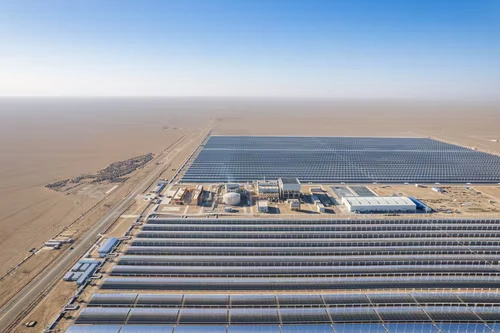
(1) To do a good job of saving electricity, it is first necessary to understand what the common electrical energy losses are and to omit some unidentified losses. Electricity losses can be divided into two main parts: fixed losses and variable losses.
Fixed losses
Fixed loss refers to the part of the loss that does not change with the load, also known as the basic loss, such as solar transformer, reactor, arc extinguishing coil and a variety of instruments, transformer iron loss, and power capacitor dielectric loss, etc., they are only related to the voltage and frequency, in the energized time, it can be considered that this part of the power loss is constant, power loss that is this constant power loss and the product of the energising time.
Variable losses
Variable loss refers to the part of the line that changes with the change of load. Such as power loss on the transmission line, solar transformer, reactor, instrumentation, transformers and other equipment such as copper loss, with the size of the load current and change, the larger the current, the greater the loss, it is proportional to the square of the current.
(2) To do a good job of power saving design, in addition to clarify the common power loss, but also pay attention to meet the following prerequisites.
The grid-connected voltage is the voltage level at which electricity is delivered to the parallel network of the public grid. It is divided into high voltage (66kV and above), medium voltage (3 to 35kV) and low voltage (380/220 to 690V) levels. When the line delivers the same power or capacity, the current flowing through the line at the higher voltage level is smaller and thus the power loss is smaller. In general, priority is given to the use of higher voltage transmission, such as medium voltage transmission priority is given to the use of 10k V level.
The location of the solar transformer should be close to the load centre.
Photovoltaic power generation is a renewable clean energy, power station operation does not require raw materials for transportation, and no pollutants are generated, while considering the less manpower and material resources required for power station operation, large and medium-sized solar power plant grid-connected booster station is generally located near the direction of the public grid connection point.
However, the booster solar transformer of each PV array should be reasonably utilised on the site topography, and should be set in the centre of the array as far as possible under the premise of facilitating operation, production management and maintenance, in order to reduce the length of the DC cable and reduce DC losses.
The solar transformer will be placed at the edge of the PV array, although it can save the investment in maintenance roads, and the use of extended low-voltage side of the DC or AC cable pooling method, will lead to a large increase in line loss, and over time its line loss capital will far exceed the initial investment.
So when the production layout decision should be timely adjustment of substation location, so that it is always in the load centre, shorten the power supply distance, minimize the low-voltage convergence line power loss, thus reducing voltage loss and cable non-ferrous metal consumption.
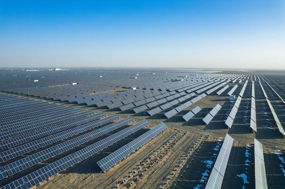
As we all know, when the line current, length, resistivity is certain, line loss and wire cross-section is inversely proportional, increase wire cross-section will reduce the wire resistance, reduce power loss and line voltage drop. However, increasing the cross-section of the wire will increase the initial investment.
For the conductor cross-section, determine how large the current density through the reasonable, to consider the issue from a technical and economic point of view: should consider the full life cycle cost of the cable, that is, not only to consider the initial cost of the cable line, but also to consider the cost of power loss during the economic life of the cable, should be consistent with the principle of making the sum of the two costs is the lowest.
The economic cross-section of the conductor is used and the cable operating temperature is much lower than the maximum permissible temperature of the cable insulation, which extends the service life of the cable line. In engineering design, under the premise of satisfying the load capacity, voltage drop and protection fit, an appropriate increase in cable cross-section will result in lower line power losses.
The problem of how to determine the capacity of a solar transformer to minimise solar transformer losses (referred to as variable losses) after the electricity load has been determined is generally based on the efficiency of the solar transformer, which is theoretically calculated to be the highest when the load factor is 50% to 60%. This is also the basis for determining the capacity of the solar transformer.
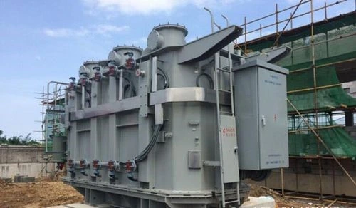
However, since this load factor is based on the design parameters of the solar transformer itself, the operation of the solar transformer is considered according to the smallest power loss per unit and the highest efficiency, ignoring the changes in load and other factors, so in practice how to determine the load factor in order to obtain the best economic benefits is still subject to comprehensive analysis.
Photovoltaic power generation is directly influenced by solar radiation, and the amount of power generated in a day is generally normally distributed, and the full load generation time is very short.
For large and medium-sized solar power plants, there may be a secondary boosting situation, where the total boosting solar transformer is installed in the pooling station and the in-situ boosting solar transformer is distributed in the PV field.
The total boost solar transformer is subject to economic and technical constraints on the installation of this type of solar transformer in the power supply sector, which is usually specified at the stage of the access system plan (generally the same as the installed capacity). For in-situ solar transformers, the load factor can be lower than the total solar transformer at the aggregation station, as they are not subject to the constraints of the power supply department.
Low-loss power solar transformer has the advantages of low loss, light quality, high efficiency and impact resistance, etc. In recent years, various low-loss power solar transformers have been widely used and have achieved significant results in saving electricity and reducing operating costs.
For new solar power plant projects, low-loss power-saving solar transformers should be used, and for distributed photovoltaic projects that have substations, they should be replaced and transformed gradually with the renewal of machinery and equipment to save electricity.
In the process of power transmission, under the condition that the active power and operating voltage of the line transmission remain basically unchanged, the power factor is improved to reduce the reactive power component of the line, thus reducing the reactive current loss in the line.
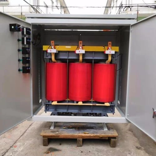
The reactive power compensation device reduces the line voltage drop and increases the load capacity of the solar transformer.
Large and medium-sized Solar power Station is generally more remote, the transmission distance is long, the voltage drop is larger, the power factor is reduced will also make the voltage at the receiving end further drop, so must be concentrated in the high-voltage end of the reactive power compensation, improve the line power factor, reduce reactive current, improve the line voltage.
High voltage static reactive power generators (SVG) use power electronics to quickly absorb or emit reactive power and compensate for capacitive and inductive reactive power, with the advantage of fast compensation and accurate tracking.
Distributed Solar Power Stations can use automatic capacitor throwing devices to automatically adjust compensation.
Distributed Solar power stations are usually connected to the public distribution network or to the low voltage side of the distribution solar transformer by means of local grid connection.
Low-voltage phase shifting capacitor automatic compensation devices can be promoted to realise automatic throwing compensation, so that the power factor is always in a more ideal state.
Unbalanced three-phase load can lead to asymmetric operation of the solar transformer, resulting in increased losses in the solar transformer.
In addition, it also has an impact on the power-using equipment. The impact of three-phase unbalance on the line loss is that: the load current of each phase is not equal, the unbalanced current is generated between the phases, these unbalanced currents in addition to the loss caused on the phase line, will also cause loss in the neutral line, which increases the total line loss, the greater the current unbalance, the greater the line loss increment.
Therefore, in the design of the single-phase power equipment classification, balanced distribution to three phases, such as lighting, socket to try to achieve internal three-phase balance; in actual operation, to regularly carry out three-phase load measurement and adjustment work, so that solar transformer three-phase current close to balance, which is without any equipment investment and very effective loss reduction measures.
In conjunction with technological advances in photovoltaic power generation equipment, higher voltage 1500V photovoltaic modules and inverters are used compared to the usual 1000V photovoltaic power generation system to increase the system voltage on the DC side of the PV system and reduce the DC system operating current, thus achieving energy saving.
In the design of large and medium-sized solar power plants, a new type of integrated inverter and booster can also be used to replace the centralised inverter, booster solar transformer and medium voltage distribution device in the original system. In addition to shortening the installation time and reducing the installation difficulty, the low-voltage cables between the central inverter and the boosted solar transformer can be omitted to improve the system’s power generation efficiency.
The solar power plant is characterised by long power supply lines and widely distributed power generation equipment. There are many measures that can be taken to reduce the power consumption of the PV power generation system, the most important of which are to reduce transmission line losses, reduce solar transformer consumption and improve the power factor of the grid. are also very important.
In short, reducing losses and improving the utilisation rate of electrical energy is of great significance in promoting sustainable economic development and building a conservation-oriented society.
Download Resource

Table of Contents Selecting the right pad-mounted transformer requires careful consideration of several critical
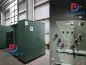
The primary function of the pad mounted transformer is to serve as a critical distribution
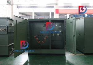
A pad mounted transformer operates through electromagnetic induction, serving as a crucial distribution component that
After filling in the contact information, you can download the PDF.