ELECTRIC, WITH AN EDGE
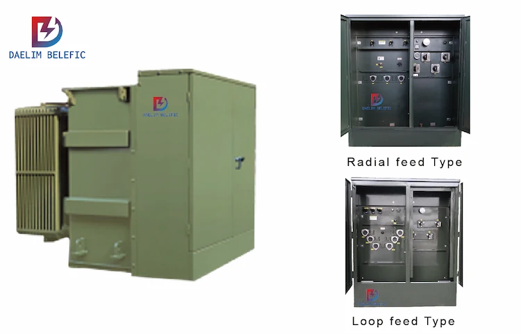
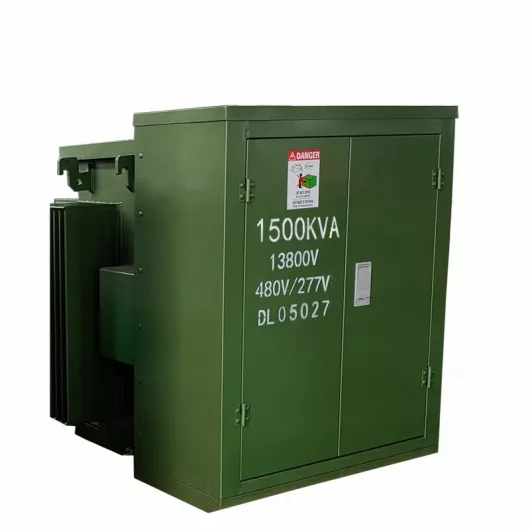
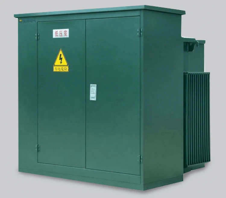
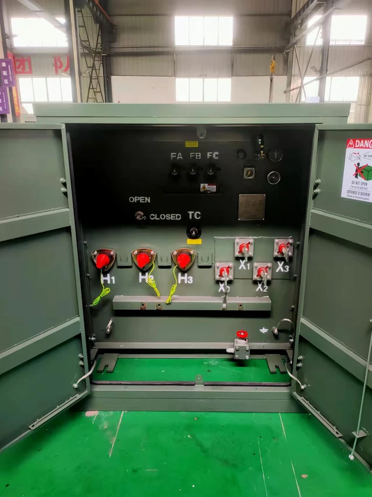
3000 kVA pad mounted transformer refers to a combined transformer with a capacity of 3000 kVA. The high-voltage cable of the transformer is connected to the transformer through a cable connector in the high-voltage bin, and the low-voltage cable is connected with a bolt and a low-voltage terminal in the low-voltage bin. Daelim’s 3000 kVA pad mounted transformer has passed IEC, IEEE, ANSI, and CSA standards testing to ensure that your transformer can be used efficiently and lastingly.
| Rated Power(KVA) | High Voltage(V) | Low Voltage(V) | Loss(W) | |
| No-load Loss(W) | On-load Loss(W) | |||
| 75 kva Transformer | 34500/ 19920 13800/ 7957 13200/ 7620 12470/ or others | 240 480 480Y/ 277 600Y 347 | 180 | 1250 |
| 112.5 kva Transformer | 200 | 1500 | ||
| 150 kva Transformer | 280 | 2200 | ||
| 225 kva Transformer | 400 | 3050 | ||
| 300 kva Transformer | 480 | 3650 | ||
| 500 kva Transformer | 680 | 5100 | ||
| 750 kva Transformer | 980 | 7500 | ||
| 1000 kva Transformer | 1150 | 10300 | ||
| 1500 kva Transformer | 1640 | 14500 | ||
| 2000 kva Transformer | 2160 | 20645 | ||
| 2500 kva Transformer | 2680 | 27786 | ||
| Tachnical Data for Pad Mounted Transformer | |||||
| Rated Power(KVA) | Dimension(mm) | Weight(kg) | |||
| W | D | H | Oil Weight | Total Weight(kg) | |
| 75 kva Transformer | 1390 | 910 | 1430 | 120 | 645 |
| 112.5 kva Transformer | 1420 | 920 | 1430 | 138 | 729 |
| 150 kva Transformer | 1510 | 980 | 1530 | 201 | 989 |
| 225 kva Transformer | 1600 | 1000 | 1660 | 230 | 1195 |
| 300 kva Transformer | 1660 | 1080 | 1680 | 260 | 1415 |
| 500 kva Transformer | 1810 | 1160 | 1790 | 325 | 1905 |
| 750 kva Transformer | 2030 | 1300 | 2030 | 535 | 2755 |
| 1000 kva Transformer | 1651 | 1549 | 1854 | 650 | 3235 |
| 1500 kva Transformer | 2210 | 1470 | 2150 | 748 | 5835 |
| 2000 kva Transformer | 2380 | 1600 | 2220 | 950 | 6430 |
| 2500 kva Transformer | 3070 | 1650 | 2330 | 1020 | 8865 |
The load factor is an index to measure the heavy overload of the distribution transformer. When the load rate is greater than 80%, it is heavy load. When the load rate is greater than 100%, it is overloaded.
We usually see that the debt ratio marked on the distribution transformer is the maximum load ratio. The unit of the maximum load is “kW”, that is, active power; and the unit of rated capacity of the distribution transformer is “kVA”, that is, the power.
Due to the existence of reactive power, it is meaningless to directly compare the maximum load with the rated capacity, and the units of the two are not the same.
Therefore, dividing the maximum load directly by the rated capacity of the distribution transformer does not give the true load rate of the distribution transformer.
There are two ways to calculate the load factor of distribution transformers:
Regardless of the algorithm, the two units involved in the calculation should be consistent, so that the calculated result is meaningful. If the actual output maximum active power, maximum apparent power, and maximum current of the distribution transformer are substituted into the above calculation method, the maximum load rate of the distribution transformer is obtained.
Transformer capacity units usually have volt-ampere (VA), kilovolt-ampere (kVA) or megavolt-ampere (MVA).
In addition, we often see transformer power units in watts (W), kilowatts (kW) or megawatts (MW). ,
Then how is the transformer kVA converted into kW?
The unit of apparent power is kVA, which includes active power (kW) and reactive power (kvar), and kilowatts (kW) = kilovolt-ampere (KVA) multiplied by the power factor, the higher the power factor, the output power of the transformer The bigger it is.
The capacity specified on the transformer nameplate is its rated capacity, which is the product of the rated no-load voltage, rated current and the corresponding phase factor; and kilowatts refers to the power of an electrical appliance, which is the actual output power of the transformer, so these two units should not be confused .
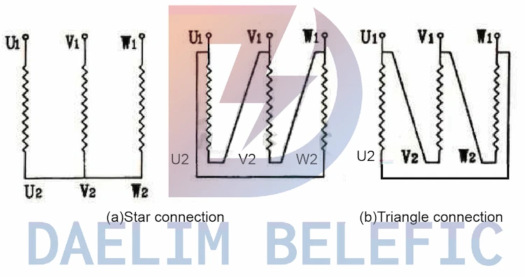
In a three-phase transformer, the three primary coils are connected to the three-phase AC power supply by two solutions, namely star connection and delta 0 connection.
As shown in the following figure (a) and (b).
When the star connection (Y-shaped) connection, when the first end 1U1, 1V1, 1W1 is the lead-out end, connect the three-phase end 1U2, 1V2, 1W2 together to become the neutral point.
If the neutral point is to be led out, use “N” mark, the wiring method is represented by YN.
Similarly, the connection of the three auxiliary coils should also have these two connections.
Both the primary and secondary windings of the three-phase transformer can be connected in star or delta.
When using star connection, the neutral point can be drawn or not, so the primary and secondary windings can have the following combination: Y/Y or Y /Yn; Y/△ or Yn/△; △/Y or △/Yn; △/△ and other connection methods.
However, these combination symbols are not enough to fully explain the entire situation of the connection relationship between the primary and secondary windings.
The clockwise notation should be further used to illustrate the phase relationship of the electromotive force between the primary and secondary windings.
There are two hands on the clock plate, 12 characters, divided into 12 grids, each grid represents a clock, the angle of a circle is 360°, so each format is 30°.
Calculated in the clockwise direction of the short hand, for example, between 12 o’clock and 11 o’clock should be 30°*11=330°; conversely, if the clock hand rotates forward 300°, it must indicate 300°/30°=10 o’clock.
The connection group of the transformer is to illustrate the phase relationship between the primary and secondary sideline voltages by means of a timepiece.
If the transformer has been out of service for one month, the insulation resistance should be measured before the power supply is restored, and it can be put into operation only after it is qualified.
Transformers that have been put on hold or out of service for more than six months should be tested for insulation resistance and insulating oil voltage before being put into operation.
For special transformers for drainage and irrigation in dry and cold areas, the outage period can be appropriately extended, but it should not exceed eight months.
After filling in the contact information, you can download the PDF.