
How to Choose Pad Mounted Transformer?
Table of Contents Selecting the right pad-mounted transformer requires careful consideration of several critical
ELECTRIC, WITH AN EDGE
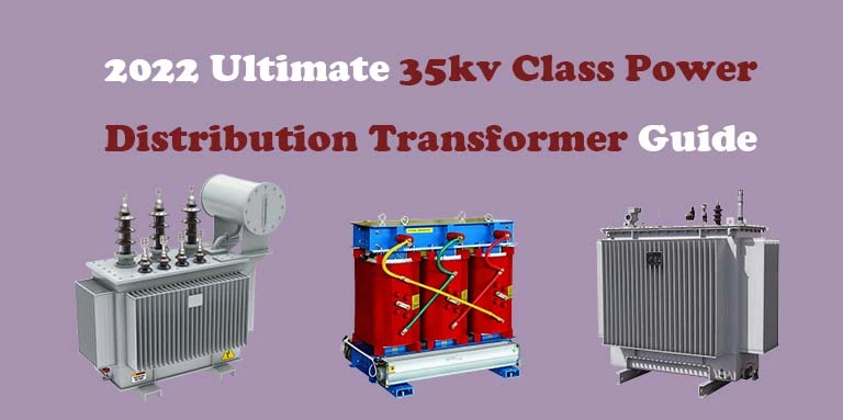
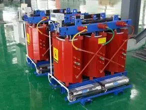
35kv distribution transformers include three-phase epoxy resin dry-type transformers and three-phase oil-immersed distribution transformers.
The rated capacity range of 35kv three-phase epoxy resin dry-type transformer is: 50~2500kva, high voltage 38.5kv, low voltage 0.4kv, using DYN11, Yyno connection group.
V
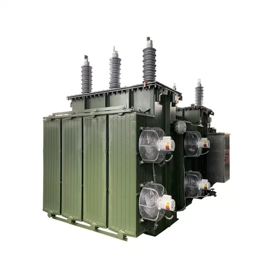
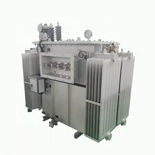
The rated capacity range of 35kv three-phase oil-immersed distribution transformer is: 800~31500kva, high voltage: 35~46kv, low voltage 6.3~13.8kv, using Yd11, Ynd11 connection group.
This article will tell you in detail about the 35kv three-phase oil-immersed distribution transformer.
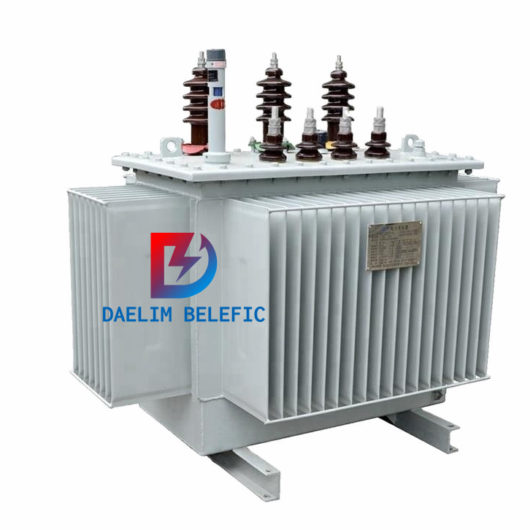
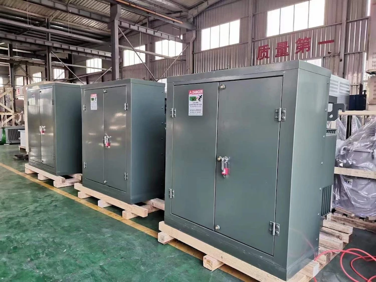
Daelim can provide you with dry or oil immersed 35kv distribution transformers. They have all obtained industry standards such as IEEE, ASNI, CSA. These standards can be used to ensure the quality of the transformers you purchase. At the same time, daelim also provides you with a two-year after-sales warranty. Daelim’s installation team in North America can also provide you with professional installation services according to your specific installation location.
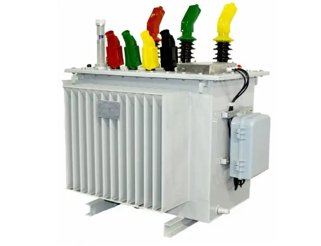
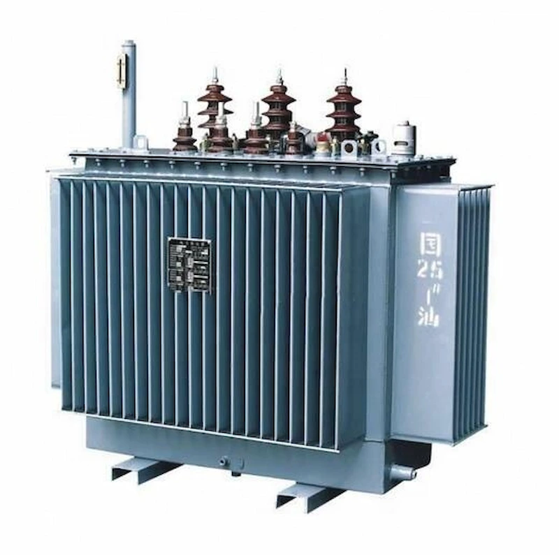
35kV distribution transformer refers to the oil-immersed transformer with high voltage 35kV, low voltage 0.4kV and capacity range of 50~1600kVA.
The 35kv distribution Transformer directly supplies power to the distribution network, and is a product with a large amount of applications and a wide range of applications. The traditional 35kV class 9 product with a capacity of 50-1600kVA adopts a single-segment multi-layer cylindrical structure for its high-voltage winding, a 50-500kVA low-voltage winding adopts a cylindrical structure, and a 630-1600kVA low-voltage winding adopts a new spiral structure. .
There are many parallel winding wires in the spiral winding, the lead wire is difficult to make, the transposition of the wires may be incomplete, and the leakage magnetic potential between the wire groups is large.
The end of the transformer coil using this winding needs to use a laminated wood end ring to enhance the short-circuit resistance of the coil. stability.
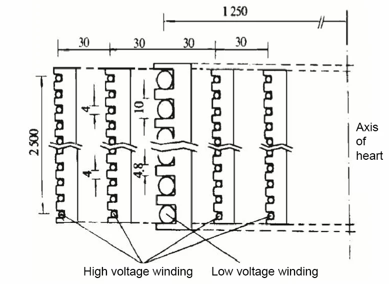
The high-voltage winding of the 35kV distribution transformer adopts a segmented multi-layer cylindrical structure.
This structure has stable electrical performance and impact resistance; the voltage between winding layers is low, which can reduce the amount of partial discharge; there is a radial oil channel in the middle, which can increase the heat dissipation area of the winding.
The low-voltage winding adopts foil winding, which improves the filling factor of conductive material in the iron window and reduces the volume of the transformer;
Increase the thermal conductivity of the winding radial direction, low temperature gradient, good thermal stability; high mechanical strength, strong short-circuit electric power, strong impact resistance, and high electrical strength.
Once the core diameter of the 35kv transformer is determined, the potential size of each turn of the winding of the 35kv transformer mainly depends on the magnetic flux density.
Since the voltage level of the winding is fixed, the number of turns of the winding is inversely proportional to the magnitude of the magnetic flux density, and the impedance voltage is proportional to the square of the number of turns of the winding, so the value of the impedance voltage has a certain relationship with the magnitude of the magnetic flux density.
Therefore, when selecting the magnetic flux density, it is necessary to ensure that the impedance voltage, no-load loss and no-load current meet certain technical requirements.
The winding type is determined by the capacity of the 35kv transformer. The high-voltage and low-voltage windings with a transformer capacity of 50kVA to 315kVA are all double-layer or multi-layer single-section cylindrical windings.
The high-voltage winding with a capacity of 400k VA to 1600k VA is a segmented multi-layer cylindrical winding, and the low-voltage winding is a foil winding.
Copper foil is used for low-voltage windings of 400k VA and above, and the resistivity is 0.02097Ω.mm2/m at 75℃ and 0.01725Ω.mm2/m at 20℃;
The low-voltage winding of 315k VA and below adopts paper-clad copper flat wire (ordinary oxygen-free copper wire), the insulation thickness is 0.3mm, and the width-thickness ratio is between 2.5 and 7;
High-voltage windings of 1000k VA and below use acetal enameled round copper wire, 1250k VA~1600k VA use acetal enameled flat copper wire or paper-coated flat copper wire, the resistivity of the enameled wire at 75 ℃ is 0.02135Ω.mm2/m, At 20℃, it is 0.01756Ω.mm2/m, and the width-thickness ratio of enameled flat wire is 2.5~6;
The electrical density of the winding wire is between 2.5 and 3.5A/mm2.
The no-load characteristics of a 35kv transformer mainly refer to no-load current and no-load loss, which are one of the main performance indicators of the transformer.
The no-load characteristics of the transformer mainly depend on the core structure, silicon steel sheet grade and magnetic flux density.
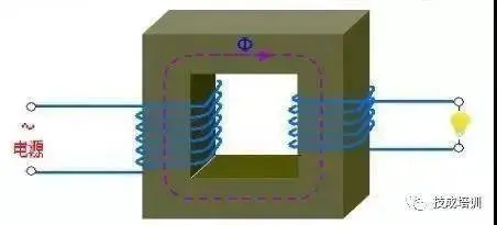
The magnetic potential (I0N) and magnetic flux (Φ) of the 35kv transformer are generated by the no-load current (I0), and the no-load loss is due to the magnetic flux.
It mainly passes through the iron core, and a certain loss will be generated in the iron core silicon steel sheet. No-load loss is mainly core loss, includingIt includes hysteresis loss and eddy current loss.
The no-load loss does not change with the load. Generally, only by adjusting the magnetic density and changing the insulation structure can the purpose of reducing the no-load loss be achieved.
The weight of a 35kv transformer consists of the silicon steel sheet, the weight of the windings, and the weight of the transformer oil.
The main material of the transformer core is silicon steel sheet, which is one of the main materials of the transformer.
The main material of 35kv transformer high and low voltage windings is copper wire.
Four types of copper wires are mainly used in the series products studied in this paper, namely enameled copper flat wire, enameled copper round wire, paper-coated copper flat wire and copper foil.
According to the unit price, it can be divided into enameled copper wire, paper-coated copper flat wire and copper foil.
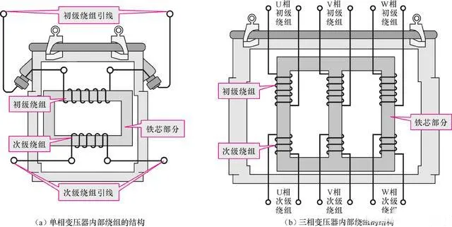
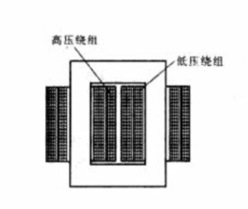
The power transformer of the core structure adopts the concentric winding of circular section.
The winding of circular section is very stable under the action of tensile force and compression force, the wire length is the smallest under the condition of a given effective section of the iron core, the operation is reliable, and the manufacture is simple.
Concentric windings are cylindrical. The heights of the high voltage and low voltage windings are approximately the same.
The high-voltage winding is arranged outside, and the low-voltage winding is directly sleeved on the core column.
35kV distribution transformer windings usually take the following forms: single-layer type, segmented-layer type, spiral type, continuous type, foil type.
The continuous winding is generally used as the outer winding of the 35kV distribution transformer and has the following characteristics:
The winding is composed of several round pie-shaped wire pie. The bus pie is generally between 30 and 100, and it is an even number. The number of parallel wires is generally not more than 4, and the maximum is 6.
Under normal circumstances, the odd-numbered pie is called “reverse pie (or reverse segment)”, starting from the winding end, and the wire is wound from the outside to the inside. Even-numbered cakes are “positive cakes (positive segment)”, and the wires are wound from the inside to the outside. A reverse pie and an adjacent positive pie form a unit, called a “double pie unit”. The oil passages inside the unit are called “outward oil passages”, and the oil passages outside the unit are called “inward oil passages”; in special cases (such as the outgoing wires of the windings are drawn from the inner diameter side), count from the winding end. , odd-numbered pie is positive pie, even-numbered pie is negative pie.
A positive cake and an adjacent reverse cake form a unit, the oil passages in the unit are called “inward oil passages”, and the oil passages between the units are called “outward oil passages”.
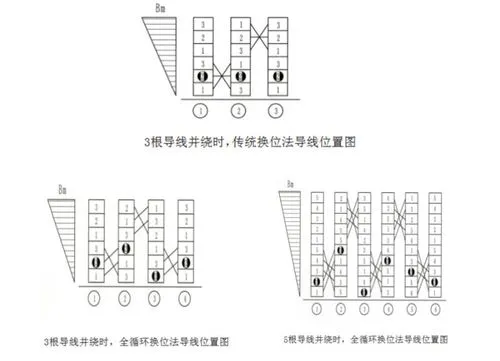
The continuous winding must be transposed, and the radial direction of the wire cake at the transposed position is higher than that of the normal part. To prevent increasing the radial size of the winding, fractional turns are used. The numerator value is generally the total number of winding struts minus 1.
The line segments of the continuous winding are all wound on the struts to form vertical oil passages on the inner surface of the winding, and spacers are pierced on the struts to form the oil passages between segments. Each turn of the winding can consist of one or several parallel wires. The coil of this structure can reduce the eddy current loss of the coil and facilitate winding.
The continuous winding end support surface is large, which is stable to axial force during short circuit, and has a large heat dissipation surface.
The capacitance of the continuous winding to ground is much larger than the longitudinal capacitance of the winding, so under the lightning overvoltage, the potential gradient between the line segments at the inlet end of the winding is large.
In view of the above characteristics, continuous coils are widely used in transformers in terms of voltage and capacity.
Under high voltage, even if a multi-layer cylindrical coil is used, the interlayer voltage is still very high, and it is difficult to ensure the dielectric strength required for the insulation between adjacent layers. In order to reduce the interlayer voltage, the coil is divided into several sections in the axial direction, so that the segmented cylindrical coil is composed of several multi-layer line segments. Its structural features are:
(1) Two multi-layer cylindrical windings are connected in series to form a segmented multi-layer cylindrical winding.
A soft angle ring and an end ring are arranged in the series connection to form inter-section insulation.
A spacer block with a certain thickness is stuck on the corresponding position of the strut of the oil passage between layers to form the oil passage between sections.
(2) The wire width should be as narrow as possible on the premise of ensuring a certain cross-sectional area and aspect ratio.
(3) Since the ground potential of the two multi-layer cylindrical windings differs by half during operation, only an electrostatic screen (high-voltage outlet end) is placed on the inner diameter side of one multi-layer cylindrical winding.
On these structures, various electrical shields are used so that when the coil is subjected to an impulse voltage, the voltage is evenly distributed across the layers of the coil. Some constructions only use a “line” shield at the beginning of the coil, while others also have an inner shield connected to the “neutral” end of the coil.
Some cylindrical coils are also equipped with capacitor rings at the end of the layer.
(4) The tap line is generally arranged at the outermost layer of the multi-layer cylindrical winding at the high-voltage outlet end, and the tap line adopts the lead-out method of the bow head.
The copper foil or aluminum foil is wound on a special foil winding machine, each layer is one turn, and the interlayer insulation is the interturn insulation.
The interlayer insulation and end insulation are wound simultaneously when the winding is wound. Foil windings are often used as low-voltage windings.
Compared with low-voltage windings wound with multiple wires, such windings have high space utilization, are convenient for automatic winding, and have high productivity.
Its characteristics are:
(1) Weld the copper bar on the metal foil as the head and end of the foil winding.
(2) The axial air passage of the foil winding is formed by the drawing bar or short glass fiber board of the corresponding heat resistance grade, which is wound in the winding winding process to form the air passage.
(3) The temperature distribution of all sections of the line segment is relatively uniform, which improves the cooling of the coil.
(4) The inter-turn capacitance is evenly distributed along the coil, and the coil increases the stability to impulse voltage.
(5) The magnetic potential of the coil is evenly distributed along the height of the high and low voltage coils, and the axial force is the smallest during short circuit.
(6) Since the ampere-turn distribution of the foil winding is easy to control, its radial leakage magnetic component is small, and the axial electromotive force caused by it is not large, so the axial compression of the transformer winding is relatively easy to deal with.
(7) The interlayer capacitance of the foil winding is much larger than the ground capacitance, so it has a good impact distribution under the action of the impulse voltage.
To sum up, combined with the characteristics of the high and low voltage windings of 35kV distribution transformers, the selection types of the windings are as follows:
(1) The high-voltage winding has high voltage, small current, and many turns, so the interlayer voltage is high.
The layered winding is selected. In order to reduce the interlayer voltage, the segmented layered winding is selected for the capacity of 400k VA and above;
(2) The low-voltage winding has low voltage and large current. Double-layer or multi-layer cylindrical windings are used for 315kVA and below, and foil windings are used for 400k VA and above.
(3)There are at most 2 longitudinal oil passages in the high voltage winding, and at most 2 longitudinal oil passages in the low voltage winding.
The concentric winding with circular cross-section is used for the power 35kV transformer of the core structure. The winding with circular cross-section is stable under the action of extension and compression forces, has the smallest wire length for a given core effective cross-section, is reliable in operation, and is simple to manufacture. Concentric windings are cylindrical in shape. The height of the high voltage and low voltage windings are approximately the same. The high voltage winding is arranged outside, and the low voltage winding is directly set on the core column. 35kv distribution transformer winding usually takes the following forms: single segment layer type, segment layer type, spiral type, continuous type, foil type.
Continuous winding is generally used as the outer winding of 35kv distribution transformer and has the following characteristics:
(1) The winding consists of a number of pie-shaped line pie, the total line pie is generally between 30 and 100, and an even number, the number of parallel roots is generally no more than 4, at most 6.
(2) In general, from the start of the winding end of the count, odd-numbered pie called the “anti-pie (or anti-segment)”, the wire from the outside to the winding system. Even number of pies is “positive pie (positive section)”, the wire is wound from the inside to the outside. A reverse cake and the adjacent positive cake to form a unit, called “double cake unit”. The oil channel inside the unit is called “outward oil channel” and the oil channel outside the unit is called “inward oil channel”; in special cases (e.g., the winding leads from the inner diameter side), the odd numbered cakes are positive cakes and the even numbered cakes are negative cakes, starting from the starting winding end. A positive cake and the adjacent negative cake form a unit, and the oil channel inside the unit is called “inward oil channel”, while the oil channel between the units is called “outward oil channel”.
(3) Continuous windings must be transposed, and the spokes of the bobbin at the transposition should be higher than the spokes of the normal part. To prevent increasing the spoke size of the winding, fractional turns are used. The numerator value is generally the total number of winding spars minus 1.
(4) Continuous winding wire segments are wound on the spacer to form a vertical oil channel on the inner surface of the winding, and the spacer is pierced with a pad to form an inter-segment oil channel. Each turn of the winding can consist of one or several parallel wires. This structure of the coil can reduce the coil eddy current loss and facilitate winding.
(5) Continuous windings have a large end support surface and are stable to axial forces during short circuits, while having a large heat dissipation surface.
(6) The capacitance of continuous winding to ground is much larger than the longitudinal capacitance of the winding, so the potential gradient between wire sections at the entrance end of the winding is larger under lightning overvoltage.
In view of the above characteristics, continuous coils are widely used on 35kV transformer both in terms of voltage and capacity.
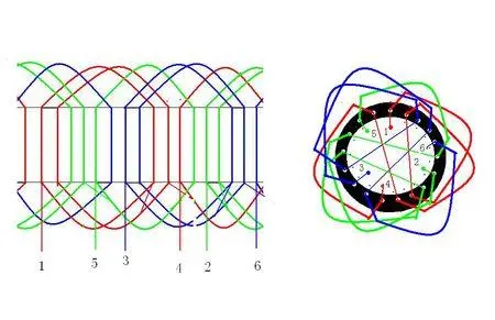
Spiral winding consists of a number of turns with oil channels between turns wound according to a spiral wire. Its characteristics are:
(1) Each turn in the spiral winding consists of several identical parallel flat wires (placed flat according to the spokes), and its shape is very much like a pie shape, therefore, the spiral winding is attributed to the pie type winding.
(2) In order to ensure a uniform distribution of current along the conductor and correspondingly reduce additional losses, multiple wires in parallel spiral winding shall be transposed, that is, the coil in the winding process of the wire turns of each parallel wire to switch positions with each other. If the transposition results in all wires uniformly arranged in the longitudinal magnetic field, this transposition is called complete transposition. When the transposition is not complete, the circulating current in the parallel wires will produce additional losses.
(3) As with continuous windings, spacers and pads are used to form the vertical oil path along the inner surface of the spiral coil and the transverse oil path between turns.
(4) The oil channel between the wire cakes is provided only for the purpose of heat dissipation, and its insulating effect is not considered.
(5) In order to compress the spiral winding evenly in the axial direction, the oil channel pads at various places inside the spiral winding must be arranged very carefully according to the characteristics of the spiral winding – spiral type of wire cake and different transposition methods, etc., and the height of the pads between the end wire turns and end circles is increased step by step to balance the spiral surface at both ends of the winding.
Spiral winding has good mechanical stability, good heat dissipation ability and processability and is commonly used in high-current low-voltage winding.
In this type of winding, single, double and multi-layer cylindrical windings are made by winding with round or flat wires. The layers of the winding are composed of closely spaced turns of wire arranged in an axial direction. The winding turns are usually made up of one or several parallel wires arranged in an axial direction. The connection between layers is achieved by transition lines. Single-layer and double-layer cylindrical windings are generally suitable for low-voltage windings of 35kV transformer with voltage below 525V and capacity below 630k VA. Its characteristics are:
(1) To increase the mechanical strength of the coil, larger insulated cardboard end turns or phenolic end turns are placed at the end of the coil. To fill the spiral surface of the end turns, insulating cardboard slats or phenolic wedge-shaped end rings are fixed to the end turns with twill fabric tape to protect the end turns from mechanical damage and to form the coil end support surface.
(2) The heat dissipation oil channel is vertical, and its cooling effect is better than that of the horizontal oil channel.
(3) The insulation between layers is thicker.
(4) The interlayer capacitance of layer winding is much larger than the capacitance to ground, so it has good shock distribution under the action of shock voltage.
Therefore, multilayer cylindrical windings can be used in high voltage products. All cylinder windings are willing to have the advantages of simple manufacturing, good cooling conditions, small probability of short circuit between turns, tight winding and good interlayer insulation.
At high voltages, even with multilayer cylindrical coils, the interlayer voltage is still high and it is difficult to ensure the required insulation strength of the adjacent interlayer insulation. In order to reduce the interlayer voltage, the coil is divided into several segments in the axial direction, so that a number of multilayer wire segments constitute a segmented cylindrical coil. The structural features are:
(1) A segmented multilayer cylindrical winding is formed by connecting two multilayer cylindrical windings in series. Soft corner rings and end rings are provided in the series connection to form inter-segment insulation. A certain thickness of gasket is glued to the corresponding position of the spacer of the interlayer oil channel to form the inter-segment oil channel.
(2) The width of the conductor is as narrow as possible under the premise of ensuring a certain cross-sectional area and width-thickness ratio.
(3) Since the ground potential of two multilayer cylindrical windings differs by half in operation, electrostatic screens are placed on the inside diameter side of only one multilayer cylindrical winding (high voltage outlet end). On these structures, various electrical shields are used so that when the coil is subjected to a shock voltage, the voltage is evenly distributed across the layers of the coil. Some structures have a “line” shield only at the beginning of the coil, while others have an internal shield connected to the “neutral” end of the coil. Some cylindrical coils are also equipped with a capacitor ring at the end of the layer.
(4) Tap wire is generally arranged in the outermost layer of the multi-layer cylindrical winding at the high-voltage outlet end, and tap wire is used to bow the head of the lead-out.
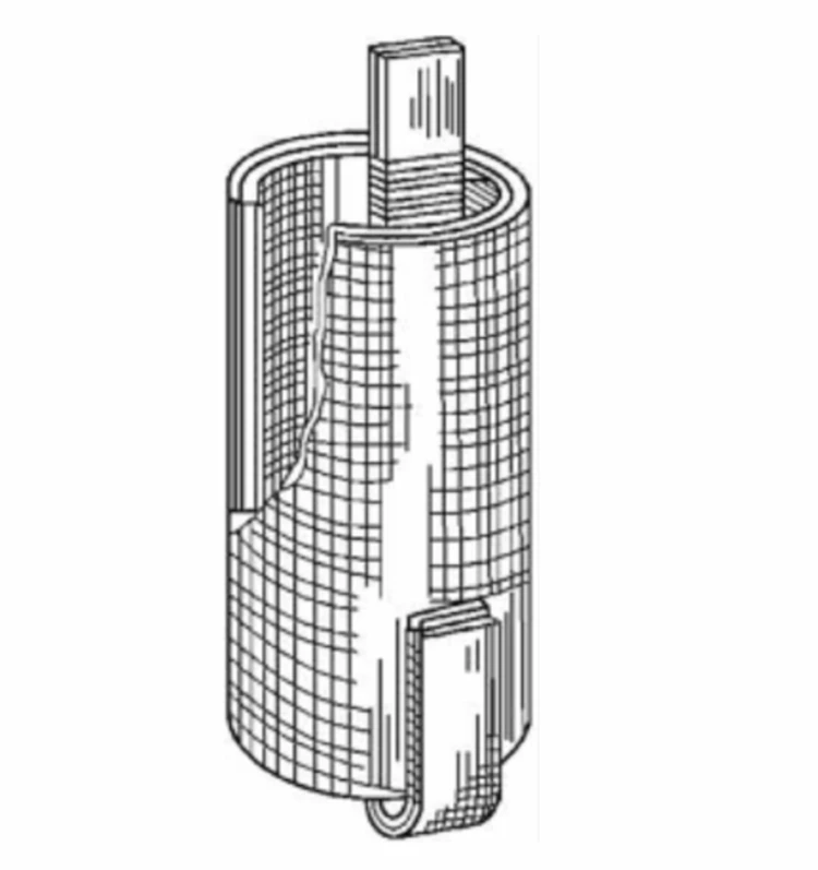
Copper or aluminum foil is used for winding on special foil winding machine, each layer is one turn, and the insulation between layers is inter-turn insulation. The interlayer insulation and end insulation are wound in the winding at the same time. Foil winding is often used as low-voltage winding. Compared with low-voltage winding with multiple wires, this kind of winding has high space utilization, easy to automate winding and high productivity. Its features are:
(1) The copper strip is soldered to the metal foil as the first end exit of the foil winding.
(2) The axial air channel of the foil winding is formed by winding in the air channel with the winding process by using the corresponding heat-resistant grade of the lead-in strips or short glass fiber sheets.
(3) More uniform temperature distribution in all sections of the wire section improves the cooling of the coil.
(4) The inter-turn capacitance is evenly distributed along the coil, and the coil increases its stability against surge voltages.
(5) The coil magnetic potential is evenly distributed along the height of the high and low voltage coils, and the axial force is minimized during short circuits.
(6) Since the foil winding amp-turn distribution is easy to control, its spoke leakage component is small, and the axial electromotive force caused by it is small, so the axial compression problem of 35kV transformer winding is easier to handle.
(7) The interlayer capacitance of foil winding is much larger than the capacitance to ground, so it has good shock distribution under the action of shock voltage.
In summary, combined with the characteristics of 35kv distribution transformer high and low voltage winding, its winding selection type is as follows:
(1) high voltage winding high voltage, small current, more turns so the interlayer voltage is high, choose layer winding, in order to reduce the interlayer voltage, 400kVA and above capacity select segmented layer winding;
(2) low voltage winding low voltage, high current, 315k VA and below use double or multi-layer cylinder winding, 400kVA and above use foil winding.
(3) High-voltage winding has at most 2 longitudinal oil channels, and low-voltage winding has at most 2 longitudinal oil channels.
Multi-layer cylindrical winding is mostly applied to the high-voltage winding of 35kV transformer. Single-segment multilayer cylindrical winding is used for high-voltage winding of 35kV transformer of capacity 315kVA and below in the series studied in this paper;
The high-voltage winding of 400k VA and above uses segmented layer winding. Both windings use enameled round wire or flat wire wound in a spiral shape, both are multi-layer cylindrical winding, they have the characteristics of layer winding, but each has its own characteristics and is suitable for different environments.
The interlayer voltage is the maximum working voltage between two layers of a layer winding. When the interlayer voltage is high (thick layer insulation), the spoke size of the winding is large, which is not conducive to heat dissipation and the consumption of copper will increase. Smaller capacity products can use graded insulation to reduce the layer insulation thickness, while larger capacity products need to use segmented layer windings to avoid the above problems by reducing the interlayer voltage.
When single segment layer winding is used for high voltage winding, the interlayer voltage is higher, the layer insulation is thicker, the winding is made with large deviation of the winding spokes, the winding process is relatively simple and the winding time is short. High-voltage winding with segmented layer winding, small interlayer voltage, thin layer insulation, small winding spoke deviation, but the production process is relatively complex, and the required time is about 1.5 times of single-segment layer winding.
The induction potential difference between adjacent points of single-section layer winding is large, the height of end ring is high, the partial discharge is large, and the insulation aging is easily accelerated during operation. The induction potential difference between the adjacent points of the segmented layer winding is small, the end ring height requirement is small, the partial discharge is smaller, and the insulation aging speed is slower during operation.
Influenced by the winding structure, the location of the regulating section of single-segment laminated winding and segmented laminated winding are different. The regulating section of a single layer winding is located at the end of the winding, while the regulating section of a segmented layer winding is located in the middle of the entire winding, and the tap section of the entire winding is formed by the tap section at the end of each segment. The tap section position is fixed and cannot be changed for single and segmented layer windings.
The insulating end ring between adjacent segments of the segmented layer winding increases the process difficulty of winding manufacturing to a certain extent, but this insulating paper ring also constitutes the spoke oil channel of the winding, which cooperates with the axial oil channel of the winding and greatly improves the heat dissipation capability of the winding. Compared with the single segment layer winding, the insulating end ring between adjacent segments also plays the role of steel skeleton in the axial direction of the winding, which greatly improves the short circuit resistance of the winding.
Both the single-section layer winding and the segmented layer winding studied in this paper use soft corner rings made of six sheets of wrinkled paper, and the structure of the soft corner rings differs between the two. The wrapping direction of the wrinkle paper is perpendicular to the wrinkle direction, and the elongation of the wrinkle paper is neglected, which can keep the oil distance unchanged. At the same time, due to the existence of multi-layer oil film in the wrinkled member, the impact voltage withstanding strength has been considerably improved. Soft corner ring using wrinkled paper compared with the use of ordinary cardboard has three advantages: First, the shrinkage of wrinkled paper has, will not become brittle after thermal aging; Second, in the 35kV transformer operation is not easy to tear, fracture or displacement; Third, the softness of wrinkled paper so that it can be made in the corner ring can be close to the end insulation parts, its shape is easy to be consistent with the isotropic surface.
The efficiency of a 35kV transformer depends on several factors, which can be broadly categorized as design, material, and operational factors. These factors contribute to minimizing energy losses during the voltage conversion process, ensuring optimal performance.
Material: High-quality core materials, such as grain-oriented silicon steel or amorphous metal, are used to reduce losses due to hysteresis and eddy currents. These materials exhibit low magnetic losses and high permeability, contributing to greater efficiency.
Design: The core design, including the shape, size, and lamination thickness, directly affects the transformer’s efficiency. For instance, a stepped or cruciform core design can provide lower losses and better distribution of magnetic flux, improving efficiency.
Material: Copper or aluminum windings are commonly used in transformers. Copper has higher conductivity and lower resistance than aluminum, which can lead to lower resistive losses and higher efficiency. However, aluminum is lighter and less expensive, making it a viable option in some applications.
Design: The winding design, including conductor shape, turns per coil, and insulation thickness, influences the transformer’s efficiency. Optimized winding designs minimize resistive and eddy current losses, contributing to improved performance.
Insulation systems:
Material: Efficient insulation materials, such as oil-impregnated paper, polymer films, or high-temperature insulating materials, minimize dielectric losses and maintain proper clearance between components.
Design: The insulation system design, including the arrangement and thickness of insulation layers, plays a crucial role in reducing energy losses and maintaining the transformer’s structural integrity.
Type: Different cooling methods are available for transformers, such as natural air cooling (AN), forced air cooling (AF), natural oil cooling (ON), and forced oil cooling (OF). The choice of cooling method depends on the transformer’s size, power rating, and installation environment. Effective cooling systems ensure that the transformer operates within its optimal temperature range, minimizing thermal losses and extending the equipment’s lifespan.
Maintenance: Regular maintenance of cooling systems, including cleaning radiators, servicing fans, and checking pumps, is essential for maintaining optimal cooling performance and efficiency.
Optimal loading: Operating the transformer within its specified load range is crucial for maintaining high efficiency. Overloading the transformer can lead to increased losses and reduced lifespan, while underloading can result in poor utilization of the transformer’s capacity.
Load balancing: Balancing the load between phases in a three-phase transformer helps maintain optimal efficiency by ensuring even distribution of power and minimizing losses.
Operational conditions:
Ambient temperature: Ambient temperature affects the transformer’s thermal performance, with higher temperatures leading to increased losses and reduced efficiency. Installing the transformer in a well-ventilated area or using proper cooling methods can help maintain optimal operating temperatures.
Voltage regulation: Maintaining stable voltage levels across the transformer’s input and output terminals is essential for efficient operation. Voltage regulation devices, such as tap changers or voltage regulators, can be used to control voltage fluctuations and improve the transformer’s overall efficiency.
Power quality is a critical aspect of modern electrical systems, as it affects the overall performance, reliability, and efficiency of connected equipment. 35kV transformers play a vital role in maintaining power quality by performing the following functions:
Stepping up or down: 35kV transformers are used to step up or down voltage levels between different parts of the power distribution network, ensuring that voltage levels are maintained within specified limits. This helps maintain stable voltage conditions for connected equipment and reduces the risk of voltage fluctuations that can lead to power quality issues.
Tap changers: Transformers with tap changers can adjust the output voltage in response to changes in input voltage or load conditions. This feature helps maintain consistent voltage levels, ensuring power quality even during varying operational conditions.
Load balancing: In three-phase systems, transformers play a crucial role in balancing the load across different phases. By distributing the load evenly, transformers help maintain power quality and reduce the risk of voltage imbalances that can lead to equipment malfunction or damage.
Harmonic mitigation:
Zigzag transformers: Some 35kV transformers are designed with a zigzag winding configuration, which is particularly effective in mitigating harmonics. Zigzag transformers provide a low-impedance path for zero-sequence harmonics, reducing their impact on the power system and maintaining overall power quality.
K-factor-rated transformers: These transformers are designed specifically to handle harmonics generated by non-linear loads, such as variable-frequency drives, electronic ballasts, and computers. K-factor-rated transformers minimize the effects of harmonics on the power system and help maintain power quality.
Low noise levels: 35kV transformers are often designed with noise reduction in mind, employing features such as tight winding construction, noise-dampening materials, and low-vibration core designs. Reduced noise levels contribute to improved power quality by minimizing the impact of transformer noise on connected equipment and the surrounding environment.
Fault protection:
Inherent fault protection: Transformers have an inherent fault protection mechanism, as they can be designed with a high level of impedance to limit fault currents. In the event of a short circuit or other fault conditions, the transformer can limit the fault current, reducing the risk of equipment damage and maintaining power quality.
Coordination with protection devices: Transformers work in conjunction with protection devices, such as circuit breakers, relays, and fuses, to isolate fault conditions and prevent them from affecting the overall power quality.
By performing these functions, 35kV transformers play a vital role in maintaining power quality within electrical systems, ensuring that connected equipment operates efficiently and reliably.
Proper maintenance is crucial for ensuring the reliable and efficient operation of 35kV transformers. Regular maintenance helps extend the transformer’s lifespan, minimize the risk of unexpected failures, and maintain power quality. Here are the key maintenance requirements for 35kV transformers:
External inspection: Regularly check the transformer for any signs of external damage, such as leaks, corrosion, or dents. Also, inspect the transformer’s cooling system, including radiators, fans, and pumps, for any signs of malfunction or wear.
Bushings and connections: Inspect bushings for signs of cracks, wear, or oil leaks. Ensure that electrical connections are clean and tight, with no signs of overheating or corrosion.
Oil sampling and testing: Periodically sample the transformer’s insulating oil and perform tests to check for the presence of moisture, dissolved gases, and other contaminants. Regular oil testing helps identify potential issues early, allowing for timely corrective actions.
Oil filtration and replacement: If the insulating oil is found to be contaminated or deteriorated, perform oil filtration or replacement to maintain the transformer’s dielectric strength and cooling efficiency.
Insulation resistance: Periodically perform insulation resistance tests to assess the condition of the transformer’s insulation system. This helps identify potential insulation issues early, preventing unexpected failures.
Winding resistance: Measure the winding resistance to ensure that the transformer’s windings are functioning correctly and to detect any issues that may affect the transformer’s performance.
Transformer turns ratio (TTR): Conduct TTR tests to confirm that the transformer’s turns ratio is within the specified range, ensuring proper voltage regulation.
Infrared thermography: Use infrared cameras to detect hot spots in the transformer, indicating potential issues such as loose connections, overheating, or insulation breakdown. Early detection of hot spots allows for timely corrective actions, preventing further damage to the transformer.
Protective device testing:
Relay and circuit breaker testing: Regularly test protective devices, such as relays and circuit breakers, to ensure proper coordination and functionality. This helps maintain power quality by isolating fault conditions and preventing them from affecting the overall electrical system.
Record-keeping and documentation:
Maintain detailed records of all maintenance activities, including inspection results, test data, and any corrective actions taken. Proper documentation allows for better trend analysis and helps identify recurring issues or potential problems.
By following these maintenance requirements, 35kV transformers can be kept in optimal working condition, ensuring their reliable and efficient operation while maintaining power quality within the electrical system.
Ensuring safety during the installation and operation of 35kV transformers is crucial to prevent accidents, injuries, and damage to equipment. Here are some key safety considerations to keep in mind:
Install transformers in a well-ventilated area with sufficient clearance from surrounding structures and other electrical equipment. Adhere to the manufacturer’s recommendations and local regulations regarding clearance distances.
Consider the proximity of the transformer to flammable materials, public access areas, and other potential hazards.
Proper grounding is essential for the safety of personnel and equipment. Ensure that the transformer’s grounding system meets the manufacturer’s specifications and complies with local regulations.
Install appropriate protective devices, such as circuit breakers, fuses, and relays, to isolate fault conditions and prevent damage to the transformer and other electrical equipment.
Ensure that protective devices are properly coordinated and tested regularly to maintain their functionality.
Provide fire protection measures, such as fire extinguishers, fire walls, or automatic fire suppression systems, as required by local regulations and industry best practices.
Regularly inspect and maintain fire protection equipment to ensure its effectiveness in the event of a fire.
Clearly display warning signs indicating high voltage areas and the presence of electrical hazards.
Install physical barriers, such as fences or walls, to restrict unauthorized access to the transformer and its surrounding area.
Ensure that personnel working on or near the transformer wear appropriate PPE, such as safety shoes, gloves, and eye protection, to minimize the risk of injury from electrical hazards.
Training and awareness:
Provide regular training to personnel on transformer safety, including proper installation, operation, and maintenance procedures, as well as emergency response protocols.
Maintain a culture of safety awareness, emphasizing the importance of following safety procedures and reporting any potential hazards or incidents.
Implement and enforce lockout/tagout procedures to ensure the safe isolation of the transformer during maintenance or repair activities, preventing accidental energization and potential injuries.
By addressing these safety considerations, the installation and operation of 35kV transformers can be carried out safely, minimizing the risk of accidents and ensuring the well-being of personnel and equipment.
35kV distribution transformer is a widely used electrical equipment.
The reduction of production cost and the improvement of product performance are of great significance to manufacturers and users.
The design of a 35kV distribution transformer is the first step in the manufacture of the entire transformer.
The quality of the design directly affects the manufacturing cost and economic benefits of the product. The high-quality design of the transformer can not only improve the operating performance of the product, reduce the design cost, but also reduce the design workload and design time.
Download Resource
Table of Contents Selecting the right pad-mounted transformer requires careful consideration of several critical

The primary function of the pad mounted transformer is to serve as a critical distribution

A pad mounted transformer operates through electromagnetic induction, serving as a crucial distribution component that
After filling in the contact information, you can download the PDF.