ELECTRIC, WITH AN EDGE
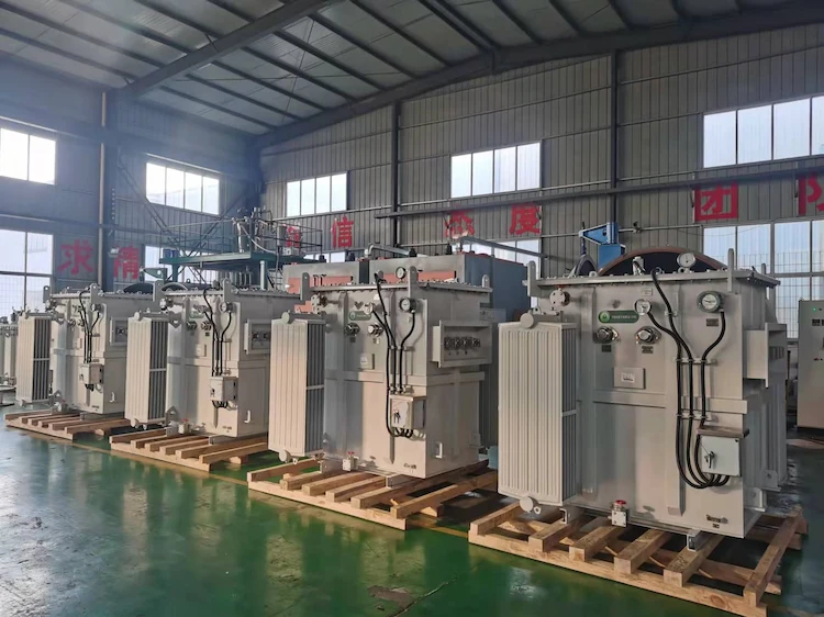
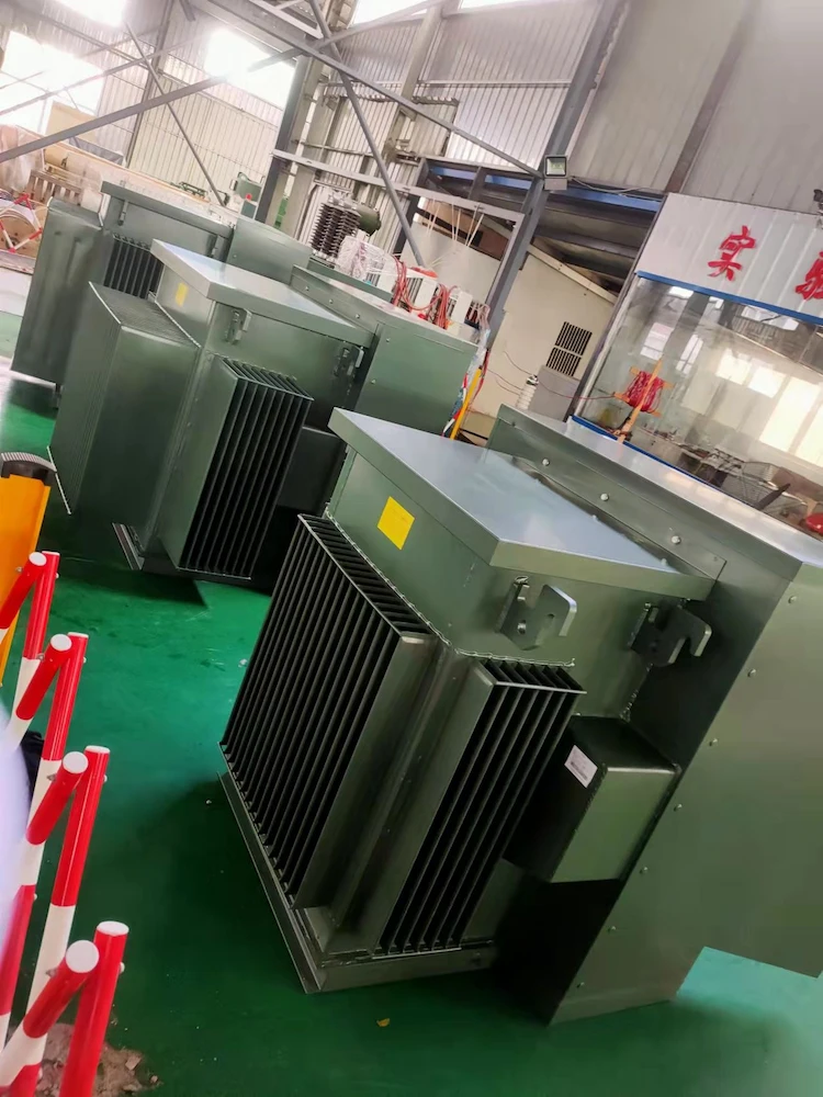
The demand for 3500 kVA transformers has significantly increased with countless consumers asking for updates with regards to the 3500 kVA transformer price, and a lot of people are going for residential pad-mounted transformers as an alternative which is why this article will also be focusing on the 3 phase pad-mounted transformer specifications.
With the growing popularity of cryptocurrency nowadays, the demand for high power-rated transformers has also increased along with crypto’s popularity, which is why DAELIM, a company that manufactures premium 3500 kVA transformers, will help you make the best purchase decision for your cryptocurrency farming needs and other projects as well.
But before diving into the complicated details about 3500 kVA transformers and the 3 phase pad-mounted transformer specifications, it is important to know the fundamentals of how a transformer works first so that you won’t be confused as we go deeper into the article.

14+FAQ ABOUT THE PAD MOUNTED TRANSFORMER
-This article introduces the various parts of the pad-mounted transformer in detail to help you understand and purchase in detail.
Mini Substation and Miniature Substation
-Mini substation and miniature substation are the smaller variant of substations with a lower kVA rating. are they worth considering?
Basically, the way 3500 kVA transformers work is the same way for numerous types of transformers as well.
As you know, there are basically 2 types of electricity in terms of the current which are A.C or “alternating current” and D.C which stands for “direct current”.
Since Residential pad-mounted transformers and 3500 kVA transformers use A.C current, it is important to learn why A.C is being used and not D.C current.
When it comes to the case for transformers, they can only work with A.C power because the moment you connect an A.C generator a loop cable is closed, the result of this will allow the current to pass through the cable, and this will also cause the current to go fluctuate with the movement of the generator.
The way the current is being alternated will cause it to able to reach the max point of its cycle, which means that there will be an efficient pattern once it is being linked to an oscilloscope. You can compare to the waves of the ocean since its direction and reach of the tide is volatile.
Once the current is passing moving through the cables, this will then emit or cause a magnetic field afterward once it is done passing through the D.C cable, this means that the magnetic field remains stagnant or somewhat balanced.
But when it comes to making the alternating current that is moving through the cable, it is important to change the magnetic field to control its strength and adjust its polarity of the current is constantly changing.
If you are utilizing multiple cables that to move various currents, then it is important for the magnetic field to properly be generated since it is responsible for combining everything to create an even stronger magnetic field.
After the process of wrapping the cable into a coil, will then make the magnetic field become stronger.
But if you choose to use a second coil within the proximity to the 1st coil, and after it moves through the A.C through the 1st coil, this will make the magnetic field induce a current that is going to the second coil.
This makes the magnetic force fluctuate in the electrons to force them to move. An important element that you should have is to change the polarity and the intensity as well.
The adjustment in the intensity and the overall movement of the magnetic field will disrupt the electrons in the secondary coil, and this will cause them to start a change in movement.
The movement is known as “electromotive force” or E.M.F.
Electromotive force will not be generated as current passes through the direct current into the 1st coil or primary coil, and this will make the magnetic field stagnant or constant, and the electrons will then be capable of moving,
When it comes to when it will generate an E.M.F, this can occur when the 1st coil is either opened or closed. Another scenario would be to increase or decrease the voltage.
The reason behind why these actions.
This means that when you utilize alternating current, I will be compatible with your project since this type of change happens regularly but the problem with this type of setup will result in a lot of magnetic fields from the primary side that is being wasted with no long-range to the secondary coil.
This type of product is no longer common since manufacturers nowadays design their core to be capable of withstanding such issues.
A great example of this is an iron core that can be found in the middle of both the primary and secondary coils.

Basically, a loop will be responsible for directing the magnetic field to a specific path towards the secondary coil which means that they will have to share a magnetic field to also improve the performance of the transformer.
The purpose of the iron core is considered not a perfect solution because it is expected that some energy will be lost through something that is known as “eddy currents”.
Wherein the current is swirling around the core, causing the transformer to heat up. This means that the energy will be mitigated.
For big projects that include big buildings and large electricity consumption, a three-phase configuration, which means that you will see these devices commonly out in public around your cities and towns.

Just to make it clear and precise, using D.C current on 3500 kVA transformers will simply not work, and it is expected that the 3500 kVA transformer will not operate through D.C supply.
Now that you understand how a magnetic field is able to induce electricity, you can try an experiment which is to put a magnet in front of a winding that is connected to a galvanometer, then let the magnet stay stationary, which means there will be no electricity flowing in the circuit, and no deflection of the needle of galvanometer but move the magnet side by side for the electricity to be induced in the winding and flow through the circuit.
This will cause the galvanometer to show that output, but what actually happens inside is that free electrons in the conductor are expected to get attracted to the magnetic field.
In the case that the magnet is stationary, the electrons will also remain in the same position after attraction, but as you move the magnet side by side, the electrons will attempt to follow the magnet and move in one direction.
This directional flow of electrons is what we call “electricity”.
So, to induce electricity, changing the magnetic field is required. When it comes to transformers, if you put D.C current into the winding, this will make a simple electromagnet with north and south pole for its tips, but since there are no moving parts in transformers to move the magnet, it will basically just act like a stationary magnet.
Hence, there will no change in the magnetic field whatsoever. This means that there will be no electricity flow in the secondary winding.
To make it possible, you will have to continuously keep changing the magnetic field, but the motion of the primary winding to do so is simply not possible, but there is a solution to it, which is changing the direction of flow continuously in the primary winding.
When the current is flowing, the other side will become the north pole while the opposite side becomes the south pole. When you change the direction of the current, the other side will become the south pole and the opposite end will become the north pole.
In simpler terms, when you change the direction, there will be a change in the magnetic field as well.
From that point on, you will be able to notice the electricity move towards the secondary winding which will still then keep flowing as you do your part in changing its direction.
The easiest way of doing this is to use A.C or alternating current since it uses a sine waveform, which means that its direction of flow is continuous.
So, by simply connecting the primary winding with the A.C supply, you will get electricity flowing in the secondary winding without any moving parts whatsoever to swap terminals each time there is a change of direction into the current.
This is the reason we use A.C current for transformers since D.C current is simply not compatible with transformers.
When it comes to 3 phase transformers, it is expected that its connection is either made out of three separate single-phase transformers or just a single 3 phase transformer unit. In terms of this setup, the coils will then be placed in a line that is within close proximity that consists of a high voltage that can be found on the outer part and lower voltage that is settled on the internal enclosure.
To put it in simpler terms, each of the coils is being totally insulated, and this means that the magnetic field will go through the two different coils to link two sides.
Furthermore, there are several configurations with one “Delta wye” as the most common form of them all.

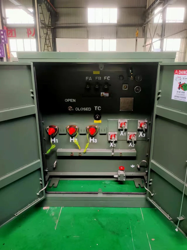
When it comes to standard features of 3 phase pad-mounted transformer specifications, this electrical device usually provides a safe working environment since it is designed to be safe for outdoor exposure.
3 phase pad-mounted transformers come with an enclosure that has a similar way of opening just like a simple school locker or your cabinet at home.
However, it is designed to open up in areas that others cannot. This is to ensure that non-authorized people or pedestrians will not be able to access it.
Every manufacturer has a standard design but you can also request your own design but this will depend on your agreement with the manufacturer.
Due to the nature of electrical utility work, it is highly recommended that whenever you open the transformer or do maintenance on it, make sure to wear the proper protective wear.
When working on a traditional 3 phase pad-mounted electrical device, the possibility of an electrical arc flash is possible.
The I.E.E.E standard 1584 specifies that how to work on a possible arc flash, and this is the standard that DAELIM is following to provide consumers a safe environment when performing maintenance on the transformer.
DAELIM designed its 3 phase pad-mounted transformers with protective devices to prevent these dangers from occurring.
After conduction countless tests using the I.E.E.E 1584 standard, DAELIM produced 3 phase pad-mounted transformers that are capable of reducing arc flash energy by more than 50%.
Therefore this reduces the danger of an arc flash danger more 3 phase pad-mounted transformers.
The same safety measures are applied to DAELIM’s 3500 kVA transformers because it is expected that during cryptocurrency mining, a lot of electrical energy is being used, which poses a great possibility of an arc flash.
In addition, personal protective equipment or P.P.E can be very hot and bulky, making it difficult to work in the environment, which is why DAELIM made their cabinets with increased workspace and enhanced airflow to make a cooler and safer area to work on the 3 phase pad-mounted transformer, which is crucial for crypto mining farms.
If your projects do involve massive electricity consumption, then you can consider using a regular residential pad-mounted transformer as they are perfectly known to do well for small to medium projects.
DAELIM also conditioned all the metal edges in their 3 phase pad-mounted transformers to be smooth and burr-free which creates an electrical device with no sharp edges to prevent cuts or injuries.
After filling in the contact information, you can download the PDF.