
How to Choose Pad Mounted Transformer?
Table of Contents Selecting the right pad-mounted transformer requires careful consideration of several critical
ELECTRIC, WITH AN EDGE
Wind energy is one of the most commercially developed energy sources in the field of renewable energy, and is a clean energy source encouraged and supported by countries around the world. Large-scale development of wind power generation should be the most realistic strategic choice to solve the energy and power shortage of countries. The main wind turbine transformer is a very important electrical equipment in the wind power project, wind turbine step up transformer capacity, type of selection is related to the entire wind power project electrical main wiring type and electrical general layout and investment in the project.
Daelim is a transformer manufacturer with decades of experience in transformer design and production, which allows us to provide you with quality transformer solutions. With our experience in photovoltaic power generation, wind power generation, bitcoin mining and other projects, we can quickly design and generate the transformers you need thanks to our excellent team of designers. Moreover, our production cycle is one of our major advantages. Our fast and flexible production allows us to produce quality transformers for you in much shorter production times than European and American manufacturers.
The capacity of the main wind turbine transformer should match the capacity of the connected wind turbine. When choosing the main wind turbine transformer capacity, consider the actual situation of the wind farm load rate is low, and the power factor of wind turbines in about 1, you can choose the main wind turbine transformer equal to the capacity of wind power plants.
Wind power plant construction scale most of the 50MW, 100MW, 200MW, individual also have 300MW and 400MW scale of wind power plant. For wind farms with a construction scale of 50MW, the main wind turbine transformer capacity is chosen to be 50MVA, which is equal to the power generation capacity of the wind power plant, in line with the principle of matching the wind turbine step up transformer capacity with the wind power airport capacity.
For the construction scale of 100MW wind farm main wind turbine transformer capacity can choose 2 sets of 50MVA main wind turbine transformer and 1 set of 100MVA main wind turbine transformer 2 kinds of options. In the specific project, the choice of which option is determined by the progress rate and technical and economic comparison.
The following analysis shows the technical and economic comparison of two options for a wind farm of 100MW and 220kV with two 50MVA main wind turbine transformers and one 100MVA main wind turbine transformer.
1. The main wiring is single busbar wiring, which is a complex wiring type.
2. 2 wind turbine step up transformer inlet intervals are required, and the total floor space is large.
1. The main wiring is single busbar wiring, which is a complex wiring type.
2. 2 wind turbine step up transformer inlet intervals are required, and the total floor space is large.
1. The main wiring uses the line – wind turbine transformer group connection line, the wiring type is simple.
2. The incoming and outgoing lines share a common interval, and the total floor space is small.
The following analysis shows the technical and economic comparison of four 50MVA main wind turbine transformers and two 100MVA main wind turbine transformers for a 200MW wind farm with a voltage rating of 220kV.
1. The main wiring is single busbar wiring, which is a complex wiring type.
2. 4 wind turbine step up transformer inlet intervals are required, and the total floor space is large.
1、The price of one 50MVA main wind turbine transformer is about 500,000 USD, and the price of four 50MVA main wind turbine transformers is about 2.02 million USD.
2. 4 wind turbine step up transformer inlet interval costs about USD 1.73 million.
1、The main wiring is single busbar wiring and the wiring type is complicated.
2. 2 wind turbine step up transformer inlet intervals are required, and the total floor space is small.
1、The price of one 100MVA main wind turbine transformer is about 870,000 USD. 2 sets of 100MVA main wind turbine transformers cost about 1.73 million USD.
2. 2 wind turbine step up transformer inlet interval costs about USD 870,000.
From the above analysis, if the wind power plant size is 100 MW, it is technically and economically better to choose one 100 MVA main wind turbine transformer than two 50 MVA main wind turbine transformers.
For a wind farm size of 200 MW, two 100 MVA main wind turbine transformers are technically and economically preferable to four 50 MVA units.
Wind power plant scale for 200MW can also choose a 200MVA main wind turbine transformer, but taking into account the wind power plant phased construction, each phase of construction capacity of 50MVA, in a phase of construction, the use of 200MVA main wind turbine transformer as a large horse-drawn cart, subsequent projects if not soon, power losses are relatively large, generally The 200MVA main wind turbine transformer of this capacity is not used.
The selection of the main wind turbine transformer type in wind power engineering mainly considers the selection of the number of phases of the main wind turbine transformer, the selection of the number of windings and the selection of the connection method, the main wind turbine transformer using three phases or single phase, mainly considering the wind turbine transformer manufacturing conditions, reliability requirements and transport conditions. The wind turbine transformer must be connected in the same way as the system voltage phase, otherwise it cannot run in parallel.
The only winding connection methods used in power systems are Y and △. The combination of high, medium and low side windings should be determined according to the specific project.
For 110kV and above, wind turbine transformer windings are Y-connected, and Y-connection is also used for 35kV. The capacity of single main wind turbine transformer in wind power generation project is generally 100MVA, which meets the requirements of three-phase wind turbine transformer from manufacturing process and transportation conditions.
The voltage level of wind turbine transformer in wind power engineering is generally 110/35kV or 220/35kV, and the wind turbine transformer is selected as a double-winding wind turbine transformer.
The wind turbine transformer winding connection can be Y/y with balance winding and Y/△ two connection methods. wind turbine transformer winding connection method using Y/y connection must add a balance winding.
When the transformer core is three-phase three-column, the connection group is Y/y, although the supply voltage is sinusoidal, but because the phase winding is not directly connected to the power supply, the end voltage on the phase winding is not necessarily sinusoidal, and the excitation current is sinusoidal (because there is no path for the 3rd harmonic current).
This 3rd harmonic flux can only pass through the core, air and shell and other components and form a circuit.
Due to the large circuit resistance, the 3rd harmonic flux is greatly weakened, so even though the 3rd harmonic potential is not small, but the 3rd harmonic flux generated as well as the 3rd harmonic potential is not large, and the phase potential can be kept basically sinusoidal. It is this smaller 3rd harmonic flux that causes additional iron losses in ferromagnetic objects such as iron clamps and tanks, reducing the efficiency of the wind turbine transformer and causing local overheating.
If in the above case, attached to a △ winding (called △ wiring third winding), the situation is different, then a very small 3rd harmonic flux in the △ winding to produce a 3rd harmonic current, it produces the 3rd harmonic flux to offset the original core of the 3rd harmonic flux, so that the core of the synthetic flux is basically a sine wave.
For the magnetic circuit, its effect is the same as the case of the original side with 3rd harmonic excitation current, the flux and phase voltage are close to the sine wave, and the problem of additional losses does not exist.
Therefore, in the wind turbine transformer design, when the primary and secondary sides are connected to a star, a △ winding is added to the core column to provide a path for the 3rd harmonic current, thus ensuring that the main flux and phase potential are close to sinusoidal, and the additional losses and local overheating are greatly improved.
The main wind turbine transformer is connected by Y/y with balanced winding, and there is a neutral point on both the high and low voltage side of the wind turbine transformer that can be led out.
If the Y / △ connection, wind turbine transformer high-voltage side of the neutral point can be led out, but the low-voltage side of the neutral point, which requires an additional side of the wind turbine transformer low-voltage bus switchgear installed in a special grounding wind turbine transformer, special grounding wind turbine transformer capacity should be based on single-phase grounding capacitance The capacity of the special grounding wind turbine transformer should be determined according to the single-phase ground capacitance.
The capacity of the special grounding wind turbine transformer should be determined according to the single-phase grounding capacitance current. Whether the wind turbine transformer is connected by Y/y with balanced winding or by Y/△ in the low-voltage bus of the wind turbine transformer with special grounding wind turbine transformer should be determined according to the different conditions of each project.
To scale for 100MW wind farm, the main transformer capacity of 100MVA for example, according to past project experience, wind power plants such as the use of overhead wire connection capacitive current of about 50A, grounding variable capacity of about 600VA, such as the use of cable connection capacitive current of about 250A ~ 300A, grounding variable capacity of about 3 000kVA ~ 3 500kVA, if the grounding transformer also do station transformer, capacity will reach 4 500kVA, after consulting with the manufacturer, 4500kVA grounded wind turbine transformer equipment volume, covers an area of large.
Therefore, wind power plant collector lines using cable connection due to capacitance current is large, the use of low-voltage bus installed in the ground wind turbine transformer grounding is not appropriate. Wind power plant collector lines using overhead conductor connection, can be used Y / y with balanced winding connection and can be used Y / △ in wind turbine transformer low voltage side bus plus special grounding wind turbine transformer connection.
In the design of the main wind turbine transformer mostly use Y / y with balanced winding connection, mainly in the pre-engineering design stage A can not determine the wind power plant collector line connection, wind power plant either using cable connection or overhead wire connection Y / y with balanced winding connection method are applicable, in addition to Y / y with balanced winding connection is simple wiring, less equipment, low failure rate. equipment, low failure rate.
After consulting with the wind turbine transformer manufacturer, the capacity of 100MVA main wind turbine transformer using Y / Y with balanced winding connection than the use of Y / △ connection in the price difference of about 45,000 U.S. dollars.
The capacity of 4500kVA grounded wind turbine transformer and high-voltage switchgear is about $57,000. Therefore, the main wind turbine transformer using Y / Y with balanced winding connection and the use of Y / △ connection with grounding wind turbine transformer in the price difference is not significant.
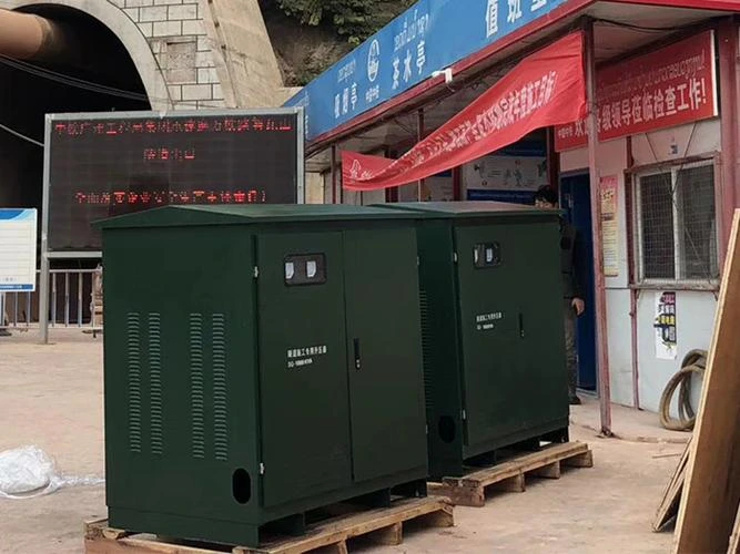
The pad-mounted transformer wind turbine is widely used in wind power plant projects because it is easy to transport, simple to operate, flexible to install and easy to maintain. pad-mounted transformer wind turbine generally consists of three parts: transformer room, high voltage room and low voltage room.
The pad-mounted transformer wind turbine can be roughly divided into two types according to its structural form and the type of components used: YB-PRE Compact Substation and pad mounted transformer wind turbine.
In recent years, with the development of technology and the increasing requirements of the power grid for the wind power industry, the pad-mounted transformer wind turbine has been improved on the basis of the American transformer and designed for wind power.
The pad-mounted transformer wind turbine is the first stage of the wind power plant voltage boosting equipment, the high-voltage side of the rated voltage is generally 35kV, low-voltage side is generally 690V.
As the distribution of wind turbines in wind power plants is relatively scattered, the distance between wind turbines and wind turbines is relatively far. In order to reduce the energy loss between the wind turbine and pad-mounted transformer wind turbine and shorten the wind turbine power cable, the wind turbine and the pad-mounted transformer wind turbine generally use a unit wiring combination of one machine and one transformer, which not only reduces the energy loss, but also reduces the investment in equipment.
Offshore wind turbines generally use the scheme of placing the pad-mounted transformer wind turbine inside the tower, while other wind power plants generally install the pad-mounted transformer wind turbine on the wind turbine platform with a distance of about 20m between the center of the tower.
The technology is mature, the high voltage side has visible disconnection points, easy to operate and safe, easy to replace the fuse; transformer body oil is stable and not easy to be contaminated, long service life; each unit structure (high voltage, transformer, low voltage) independent, can be customized according to user requirements, the structure is rich and diverse. However, the volume is large, transportation and installation is difficult, heat dissipation is poor, the price is expensive, and the cost is the highest than the U.S. transformer.
The technology is mature, the high-voltage components are enclosed in the transformer tank, and there is no visible disconnection point on the high-voltage side. In order to facilitate maintenance, the front overhead line is generally required to install a fall insurance, and the insurance position is relatively high, difficult to operate, and often due to the failure to close the arc situation; high-voltage components need to open the tank when the fault, complicated maintenance, reliability is slightly worse, if the fault outage period is longer, corrosion resistance is poor; but good heat dissipation conditions, compact layout, small size, low price.
daelim’s pad-mounted transformer wind turbine combines the advantages of American substation and European substation, commonly known as compact pad-mounted transformer wind turbine power station, generally using one machine and one change mode; daelim’s pad mounted transformer wind turbine and pad mounted transformer wind turbine transformer, load switch and low-voltage outlet mode are basically the same, but daelim’s pad-mounted transformer wind turbine has a separate transformer room. Since both the high and low voltage sides appear on the side walls, the transformer room does not require protective barriers or other facilities. The transformer is partially exposed outside the cabinet, so that it can take full advantage of the windy nature of wind power to dissipate heat naturally and save investment costs.
Compared with pad mounted transformer wind turbine, daelim’s pad-mounted transformer wind turbine has increased lightning arrester and grounding switch. In order to ensure that no harm is caused to human body during the maintenance of the pad-mounted transformer wind turbine, a mechanical interlock is set between the grounding switch and the main switch.
A high-voltage surge arrester is installed in the cabinet, and the switch can be operated easily by using a special distribution handle to close and break the switch, and a transparent window is provided to observe the status of the main switch.
The pad-mounted transformer wind turbine of daelim uses one fuse per phase, so that when any one phase fuse breaks, the load switch will be tripped, and must be replaced by a new fuse in order to make the main switch close, which is pad mounted transformer wind turbine using two fuses per phase for protection does not have.
Generally inland mountains or plains wind power plants in order to economic reliability and ease of maintenance, field voltage generally choose 35kV, padmounted transformer wind turbine voltage using 0.69kV / 35kV wind turbine step up transformer, field lines are generally used overhead line cable mixed lines and pure cable lines, for cable overhead mixed lines pad- mounted transformer wind turbine high-voltage side to the overhead line using cable, cable on the tower generally using direct connection, plus the installation of drop insurance and isolation switch mode, for pure cable lines pad-mounted transformer wind turbine high-voltage side using cable access, multiple circuits using cable intermediate box convergence distribution. Comprehensive wind power plant and wind power generation characteristics, wind power with pad-mounted transformer wind turbine has the following technical characteristics.
(1) Low-input-high connection mode: Inlet and outlet lines are cable connection mode, with 690V inlet line on the low-voltage side and 35kV outlet line on the high-voltage side. At present, the rated voltage of the wind turbine output is generally 690V, which is generally stepped up to 35kV through the wind turbine step up transformer and gathered in the field line to the wind farm substation 35kV bus side distribution device.
(2) The transformer capacity is small and the no-load time is long. At present, the power of onshore wind turbines is generally 2 ~ 3MW, transformer capacity in the following 4000kVA, due to wind power has a very obvious seasonality, in the selection of padmounted transformer wind turbine voltage must choose a slightly smaller no-load loss to improve the economic operation performance.
(3)due to the mountain wind power road environment is complex, the wind turbine is more dispersed, padmounted transformer wind turbine voltage operation and maintenance is more difficult. The U.S. high voltage side without obvious breakpoints, easily affected by wind, snow and rain safety operation; YB-PRE Compact Substation overhaul high voltage side with obvious breakpoints, not easily affected by the environment, less maintenance; Daelim phase change overhaul with breakable points, easy to overhaul.
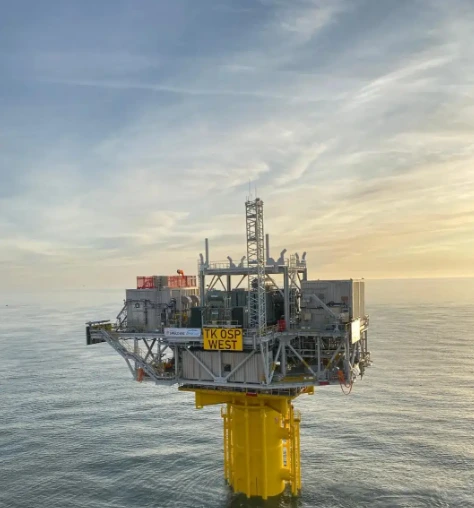
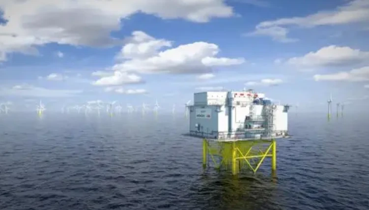
As a key component of a large offshore wind power plant, the offshore AC step up substation is the hub for the power delivery from the offshore wind power plant, and its design optimization plays a very important role in the economy, reliability, availability, maintainability and safety of the construction and operation of the entire wind farm.
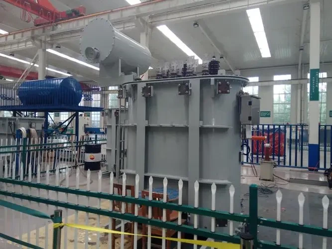
The construction of wind power step up substation has high requirements for transformers. Each wind turbine needs to be equipped with one wind turbine step up transformer. Due to the unstable output power of wind power, the transformer has high no-load and load losses, so the energy saving of the transformer is required.
Especially for offshore wind power transformer, it needs to be installed in the tower or nacelle, so it requires a small size and strong resistance to salt spray corrosion.
In addition, the installation and maintenance costs of transformers for offshore wind power are high, so it is necessary to ensure that the products have high reliability.
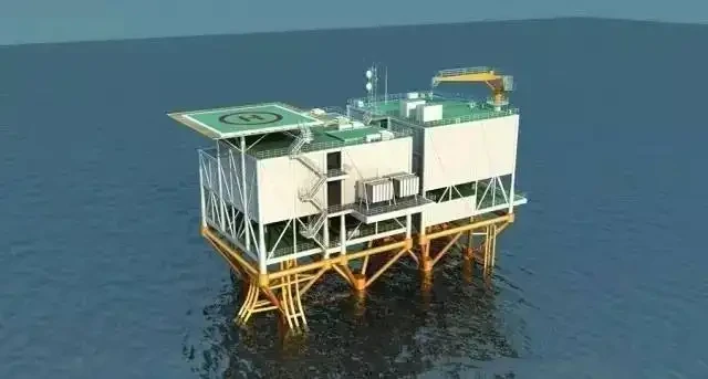
Offshore platforms are mainly used to carry the core equipment of substations: main transformers, grounding transformers, medium and high voltage switches, reactive power compensation devices and related ancillary facilities (such as helicopter platforms, lifts, standby generators and distribution power lighting systems, etc.). In order to reduce unnecessary system losses and enhance the reliability and flexibility of power transmission, the power generated by the wind turbine needs to be raised to a suitable voltage before transmission to shore, a process in which the main transformer and high-voltage switch (GIS) are indispensable equipment.
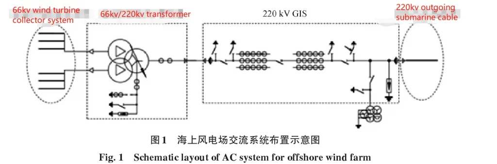
For current offshore wind farms, typically the main transformer raises the 33 kV wind farm collector voltage to a transmission voltage of 220 kV (rarely 110 kV) and then connects to an onshore substation via a 220 kV GIS and 220 kV outgoing marine cable for integration into the main onshore grid.
A typical AC system arrangement for an offshore wind farm is shown in Figure 1, where the main transformer is typically rated at 100 to 300 MVA. next generation wind farms have even higher ratings, with turbine collector voltages of 66 k V and transmission voltages of 220 kV, in which case the transformer rating is also increased further.
As the mainstream structural design, offshore platforms and substations mostly adopt “enclosed” structure to place all electrical equipment required by customers in “indoor” to facilitate the protection of equipment and post-maintenance, and the mainstream projects are currently adopting similar enclosed design.
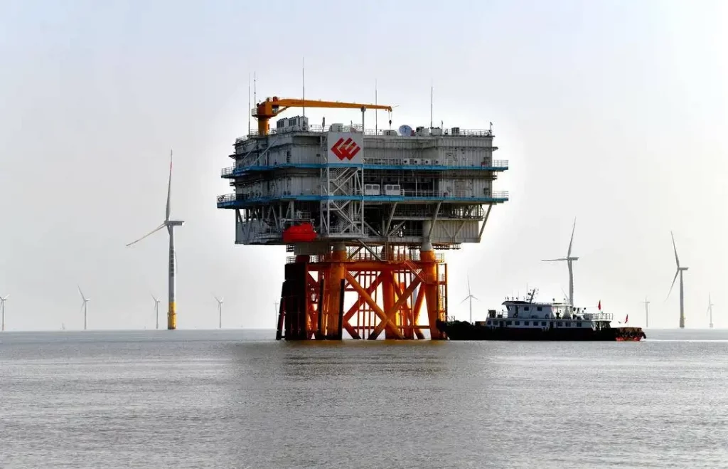
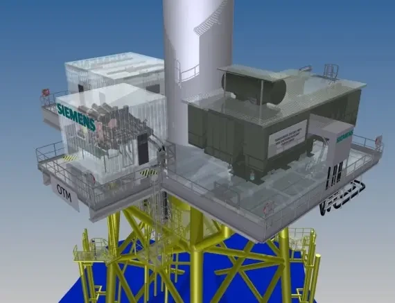
In addition, in recent years there has been a relatively new distributed modular substation solution (offshore transformer module (OTM)) with an open design: all equipment is installed on a flat, open base platform after configuration optimization and streamlining.
In this technical solution, the high voltage GIS and low and medium voltage equipment are placed inside the container, while the main transformer is completely exposed outdoors, as exemplified in Figure 3. This OTM solution will be further described in the following section.
Space is extremely valuable for offshore platforms and when starting to consider how to transfer the platform offshore and support and install it, it soon becomes apparent that the size and weight of the substation is critical and the more compact the design, the less supporting steel structure is required, resulting in a lighter platform and support structure, and therefore a cheaper overall system and lower construction costs.
Therefore, while meeting the basic requirements for safe operation and easy maintenance of the equipment, the compactness and optimization of the overall arrangement of the substation equipment are of great significance for the cost savings of the project.
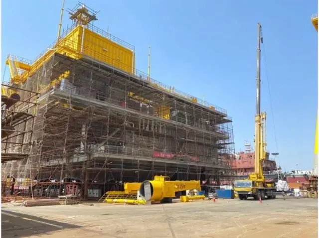
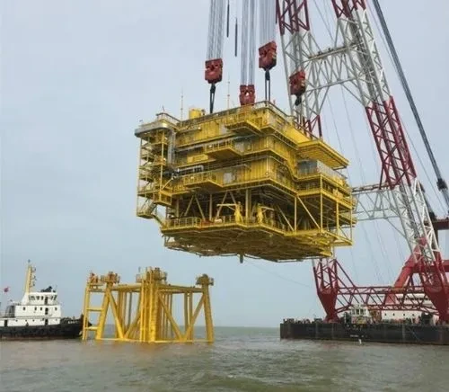
In particular, it should be noted that for the consideration of construction cost and operability, the main equipment (including the main transformer and GIS) of the offshore step up substation should be completed in the onshore dock for the overall installation, commissioning and main handover test, and the whole transported to the wind farm for lifting. At present, this operation method is widely recognized and applied in the development of wind farms in various countries.
Based on the special operating conditions of offshore step up substation, the design and selection of transformers should be considered from multiple dimensions and targeted technical requirements should be formulated to ensure that the initial selection, post manufacturing, installation and commissioning, safety, maintenance and other aspects of the transformer can be based on the special characteristics of offshore step up substation to maximize the reasonable integration.
From the application history, the existing transformer design and selection standards and operation specifications are mainly formulated for traditional onshore transformers, and the current technical requirements of Offshore Transformer also follow the general requirements of onshore transformers as the main technical basis, adding considerations for the special environment at sea, typically the special anti-corrosion requirements for metal structure parts, and from the perspective of reducing maintenance From the perspective of reducing the workload, the cooling method is mostly chosen as natural cooling without fans.
From the point of view of achieving the basic functions, Offshore Transformer follows the basic technical selection ideas of onshore transformers as a minimum requirement. The safety and reliability of the transformer, the economy of selection, and less maintenance considered in the selection and development of technical requirements for onshore transformers are also applicable to Offshore Transformer from the principle.
But from the viewpoint of the special characteristics of offshore step up substation, the transformer applied to offshore step up substation, if only in accordance with the general requirements of land-based transformers as the main basis for selection and simply expand, this idea in fact limits the main body from Offshore Transformer services – The design and selection of Offshore Transformer should first serve the safety and reliability, economy and overall ease of maintenance of the offshore platform, and not only from the perspective of transformer.
As mentioned earlier, the cost of completing work offshore is typically considered to be about 10 times the cost of equivalent work onshore. Maintaining an offshore platform or repairing and replacing a transformer would be an expensive and significant undertaking, so the reliability and safety of the Offshore Transformer should be higher than that of an onshore transformer.
Due to the difficulty of quantifying the operational reliability of the technical requirements and the general requirements of the onshore transformer, there are currently no clearer requirements for product reliability in the selection and technical documentation of the Offshore Transformer.
Nevertheless, the design and manufacture of transformers must consider more stringent design basis and calibration principles, such as the transformer insulation construction and short-circuit resistance must ensure sufficient design margin, the body fastening should take into account the continuous shaking of the offshore platform, etc. to strengthen.
Special attention should be paid to the fire safety considerations of the Offshore Transformer.
Due to the huge volume and full of mineral oil, the fire protection of Offshore Transformer is the key to the fire protection of all electrical equipment on the offshore platform, which is the most important to ensure the overall safety of the platform.
While improving the reliability of the transformer itself, the failure of any external auxiliary equipment should not become a hidden danger to start a transformer fire.
For example, to prevent the fault of cable type involving transformer body oil, special attention should be paid to the isolation measures of cable termination and transformer body. In particular, the connection between the high-voltage cable and the transformer should be equipped with oil-oil sleeves to isolate the cable terminal and the transformer body, and should not bring the cable terminal into direct contact with the large amount of mineral oil in the transformer body.
For physical isolation of transformers from other equipment, onshore substations tend to first protect adjacent assets by firewalls and fire protection of transformers by active fire protection systems. Obviously, physical isolation is not easily achieved on offshore platforms, so it is important to have an active fire protection system in place.
In recent years, there has been a growing trend to improve transformer fire protection by taking high ignition point ester transformer oils, typically synthetic ester step-up distribution transformers for use with offshore wind turbines, which are installed in the upper part of the wind turbine tower and send voltage up to 35 kV or 66 kV to the offshore step up substation. synthetic esters are also used for main transformers on OTM projects abroad.
According to the CIGRE537 Technical Manual: “Guide to Transformer Fire Protection” developed by the International Conference on Large Power Grids, ester oil cannot completely eliminate fire hazards in transformers, but it can largely reduce the possibility of fire.
Currently, ester oil transformers have been developed to 420 kV voltage levels, but further applications of ester oil transformers have yet to reduce costs due to the high cost of the ester oil itself, which has caused transformer costs to rise significantly. Another characteristic of ester oil is that it is much better than mineral oil in terms of environmental protection and degradation, which is also beneficial to the marine environment. Therefore, in the long run, the prospect of large-scale application of ester oil transformers in the main transformer of offshore step up substation is very promising.
The overall cost of the offshore platform is expensive and space is valuable. In the overall layout design of the offshore platform, it is necessary to consider the arrangement and weight-bearing of the transformer first.
As the electrical equipment with the largest weight and volume in the substation of the offshore platform, the transformer should be considered for its safety and reliability, but also for its economy and reasonableness in the overall layout of the offshore platform.
At present, the economic considerations of Offshore Transformer selection follow the conventional thinking of traditional onshore transformers, only the electrical parameters and losses are considered, while the overall volume and weight of the miniaturization is usually not considered.
With the basic electrical parameters and losses as well as cooling methods already specified, the optimization of the transformer size and weight in fact depends only on whether the transformer manufacturer can offer a more optimal solution.
Due to the need to consider higher reliability, there is not much room for size and weight optimization of the Offshore Transformer. One obvious reason is that the overall size and weight of the transformer cannot be essentially miniaturized by simply relying on compressed internal insulation distances and optimized cooling structures.
Taking into account the operating environment and life expectancy of the offshore platform, one way to optimize the weight and size of the transformer may be to increase the allowable temperature rise limit of the transformer to the extent allowed by the standard, which can be done for mineral oil based transformers by adopting a hybrid or uniform high temperature insulation system, and for ester based transformers by increasing the temperature rise limit of the top layer of oil.
The equivalent international standards IEC 60076.14-2009 and IEEE 1276 have similar provisions for transformer applications with high temperature insulation systems, which have been in operation internationally for more than 20 years from the application history. For Offshore Transformer, raising the temperature rise limit will make the structural dimensions, both internal and external, as small as possible while meeting the insulation requirements.
This reduction in structural dimensions also means a reduction in weight, which has obvious positive implications for the overall layout optimization of the offshore platform.
If we consider a 20%-30% reduction in the overall size and weight of the transformer (including the heat dissipation part) as an initial goal, the cooling method can be reconsidered while raising the temperature rise limit of the Offshore Transformer.
Currently, the most common cooling method for Offshore Transformer is the natural cooling method of sheet heat sink without any other auxiliary cooling devices such as heat sink fans or oil pumps. A typical arrangement is to place dozens of sheet radiators in the outdoor space of the platform, while the transformer body is placed in an air-conditioned, slightly positive pressure indoor space, with the body and radiators connected by oil guide lines.
Obviously, there is a special reason for not placing the heat sink fans underneath or to the side of the sheet radiators as auxiliary cooling equipment, because it would be difficult to deal with the anti-corrosion problem of the heat sink fans placed in the open environment at sea, and the resulting costs of fan transportation and replacement would be too expensive in the offshore platform environment.
The case of the oil pump will be completely different from that of the radiator fan because of its arrangement in the pipeline and its flexible location.
The oil pump can be arranged in the pipeline near this end of the transformer body, that is to say, the oil pump can be installed in the same indoor environment as the transformer body with air conditioning micro-positive pressure.
The operating environment of the oil pump is in fact better than that of the onshore transformer, i.e., it is perfectly feasible to choose a reliable oil pump for the Offshore Transformer if there is a 1+1 standby, and the possibility that the oil pump will need to be replaced or even removed for maintenance during the lifetime of the Offshore Transformer is minimal. The possibility of the pump needing to be replaced or even removed for maintenance during the life of the Offshore Transformer is minimal.
The benefits of this are obvious, as the radiator oil pump cooling method will reduce the number of radiators in a purely natural cooling scenario for the same transformer losses, resulting in a reduction in the overall size and weight of the Offshore Transformer.
The choice of neutral point insulation level and grounding method is another factor to consider, as the Offshore Transformer is installed indoors and connected to the GIS equipment via cables.
The transformer is then less likely to be directly exposed to lightning surge overvoltage, while the connection to the GIS increases the likelihood of the transformer being subjected to fast transient overvoltage (VFTO), so the transformer design should consider the effects of VFTO. The insulation level and protection of the neutral point of the 220 kV Offshore Transformer can also be studied in a targeted and specific manner.
In conclusion, considering the unique environmental characteristics of offshore platforms and the importance of optimizing the overall layout of the platform, Offshore Transformer should think beyond the established thinking of onshore transformers in terms of design and selection, and flexibly apply the standards in terms of major technical parameters, such as impedance voltage, loss value, temperature rise limit, cooling method, insulation fit, etc., and fully integrate with the reality to have innovative This aspect requires close cooperation between the design unit and the transformer manufacturer, and multiple program comparison to reach the most reasonable way.
Offshore Transformer and onshore transformer installation and commissioning process and location are different. On-land transformers are generally transported from the transformer manufacturing plant to the substation site, and after installation, installation, commissioning and acceptance tests, the transformer is ready for operation.
Offshore Transformer, on the other hand, is generally transported from the manufacturing plant to the manufacturing base of the offshore platform and installed on the platform first, and in order to reduce the offshore workload, commissioning and handover acceptance tests are completed at the platform manufacturing base.
After that, the transformer is transported to the designated location by barge together with the platform in the state of oil-filled installation and lifted onto the foundation of the offshore platform.
This process and characteristics determine certain special features of Offshore Transformer corrosion protection.
① The transformer stays in the shore platform manufacturing base for a long time, usually up to several months. During this period, it is necessary to gradually complete the installation, commissioning and handover acceptance test of the transformer, which inevitably involves cross-operation process with other equipment installation process of the platform.
During the installation process the transformer body is not in the air-conditioned micro-positive pressure environment, but directly exposed to the high salt spray shore of the sea for several months, therefore, the transformer in this phase of corrosion and rust prevention should be considered in the design and installation.
For example, the transformer body and accessories should be painted in accordance with the requirements of high salt spray painting on the seashore, and anti-corrosion materials should be selected for key parts and components, such as the damage to the paint on the bottom of the box when the transformer is in place, and the damage to the paint surface from the installation bolt screw holes.
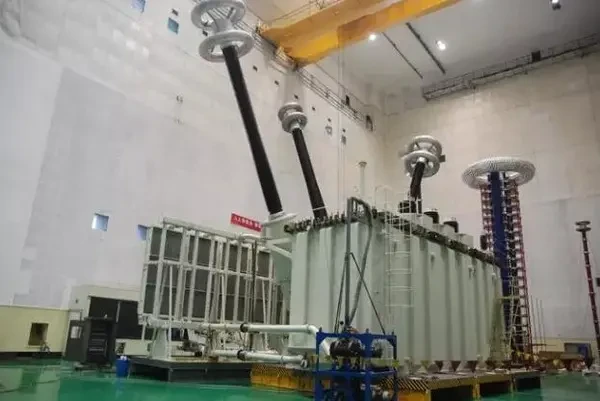
②The field test of Offshore Transformer should be carried out in different locations according to the steps. Transformer in the factory according to technical requirements and the corresponding standards for conventional factory tests, including frequency response analysis test, etc. The transformer shall be subjected to on-site handover test after installation and oil filling on the platform, including on-site high voltage test, etc.
③In order to make sure that no internal displacement occurs during the transportation of the transformer from the manufacturing base to the offshore installation, the transformer shall also conduct repeated frequency response analysis tests and insulation resistance tests after the final installation on the offshore platform.
In addition, the special operating environment of Offshore Transformer determines its high operation and maintenance cost, therefore, the operation and maintenance cost should be fully considered in the design and selection stage.
The design and manufacturing quality of the transformer body should be the first consideration. Although the location of the transformer room on the offshore platform is usually reserved with a removable roof to facilitate the lifting of the faulty transformer at a later stage, choosing a reliable product at the initial stage will obviously reduce the extremely expensive maintenance cost and the loss caused by downtime at a later stage.
In addition, all components of the Offshore Transformer should be selected for their high reliability and resistance to salt spray corrosion, which will have obvious benefits in reducing O&M workload later on.
Offshore step up substation high-voltage GIS is the connection point between the main transformer and the transmission submarine cable, although its main role is no different from that of onshore substation GIS, but because the offshore power grid structure is relatively simple, so the fault mode it faces is far less complex than the latter.
On the other hand, in view of the precious space of the offshore platform and the harsh conditions of the ocean, the design layout and selection of GIS on the platform have some different characteristics in order to keep the system power supply reliable, flexible operation, convenient operation and maintenance, and investment saving requirements.
In the European offshore step up substation, the simplest arrangement is to connect only one GIS isolation switch module with protective grounding switch between the main transformer and the outgoing cable, but if the outgoing cable is long, it is recommended to use GIS circuit breaker on the platform to connect and perform the relevant switching operation, which can avoid switching the long cable and main transformer through the onshore substation, and also The longer the cable is, the higher the chance of failure.
Sometimes, when the main transformer is energized, the circuit breaker is even required to switch on the main transformer through the phase selection device to reduce the disturbance to the grid voltage.
Many projects use such a single bus arrangement of 2 incoming intervals (connecting two main transformers respectively), 1 outgoing interval (connecting the sending and receiving submarine cables) and 1 protection interval (without circuit breakers); both incoming and outgoing intervals are wired with cables.
When cost permits, sometimes customers seek greater redundancy to improve system reliability: the GIS may have a single bus arrangement with 2 incoming intervals, 2 outgoing intervals and 1 segmented bus interval, with 2 additional protection intervals without circuit breakers. In the specific arrangement of modules, we recommend that modules such as lightning arresters and voltage transformers should be avoided under the breakers of, for example, disconnecting switches or grounding switches, in order to prevent their insulation from being affected by foreign objects that may be generated during the mechanical operation of the switches, although this may slightly increase the number of GIS modules and the length of the whole interval, but the reliability of the system in long-term operation is higher.
In order to ensure the convenience of equipment installation, maintenance and inspection, GIS should be arranged in the center as far as possible, and reserve enough space for installation and maintenance and inspection.
It should be especially noted that since the incoming and outgoing lines of GIS are in cable wiring mode, the arrangement of GIS must also consider how to meet the demand for on-site handover withstand voltage testing indoors.
At present, the test sleeve is the most conventional test method, in this case, the installation position of the test sleeve and insulation distance should be considered.
Of course, it is also possible to use mouth-to-mouth fully enclosed frequency test transformers to directly dock with the GIS for this withstand voltage test, but it is also necessary to consider the reserved design and docking space of the test interface on the bus side of the switch.
In terms of electrical performance, the following points should also be considered when selecting the type.
1) Firstly, the high reliability of the equipment, which should be maintenance-free or less maintenance as far as possible.
2) the outgoing interval circuit breaker connected to the outgoing submarine cable usually needs to meet the cut-to-length (LC2) level requirements; in extreme cases, it may even be necessary to verify its cut-to-length capability through type testing.
3) If the offshore step up substation has reactive power compensation, the circuit breaker may miss the over-zero throw point when cutting the shunt reactor and sending out the submarine cable, and corresponding measures need to be taken to alleviate this phenomenon, such as the use of phase-selective closing devices, etc.
4) send out the submarine cable has a very high electrical capacity (about the same length of conventional land overhead lines more than ten times), when the switch to cut or send out the submarine cable itself when a fault occurs, the system will generate a very high surge / oscillation overvoltage, usually must be installed in the GIS outgoing and incoming interval metal zinc oxide surge arresters on the system insulation overvoltage protection;.
5) Although the secondary equipment of GIS such as mechanism operation box, switchgear switchgear control cabinet (LCC) are placed indoors, but the change of ambient temperature/humidity will cause condensation inside the cabinet, so the cabinet still needs heater moisture removal device to prevent corrosion of secondary components and cabinet.
Compact GIS should be preferred because space is valuable.
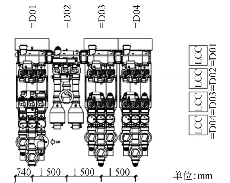
In the case of an offshore step up substation switch room of the Siemens Energy Compact 2208DN9-2 GIS, the specific dimensions and constituent components of one of the typical incoming intervals are given on the right: the interval width is only 1.5 m (smallest of its kind), the length is about 5.7 m, the maximum height is about 5 m (voltage transformer T5) and the weight is less than 5 t. The miniaturized design makes this GIS The miniaturized design makes the GIS switch room occupy less space and less floor space.
Since the lightning arrester (F1) and the voltage transformer (T5) are usually not required for field voltage withstanding, their installation location can also be used as a reserved interface for testing the test bushings. Due to the high reliability of the GIS, a single bus arrangement can usually be used to reduce the overall weight of the equipment and save space.
Of course, although this compact design can minimize the number of related GIS modules, but when a gas chamber needs to open the chamber for maintenance and the adjacent gas chamber is charged, the adjacent gas chamber can not be lowered, as the gas chamber partition basin insulators need to have sufficient mechanical strength to withstand the difference in air pressure between the two chambers, especially when the maintenance chamber is under vacuum, so these need to be given full consideration when selecting the type. GIS will cause vibration/shaking during transportation, but usually GIS equipment can meet the seismic design requirements of gravitational acceleration ≤ 0.5 g, and through the type test verification, our experience is that with proper protection measures, the GIS in transit will not be affected, with sufficient mechanical strength of the GIS in place after the wind farm does not need to re-insulate the voltage test, thereby reducing the construction cycle and reduce construction costs.
On the other hand, even after the GIS is in place, the effects from platform vibration/shaking are still present, and the necessary long-term vibration resistance measures need to be considered for the fixed structure and the connection to other equipment.
Where space permits, it is recommended that the main transformer be connected by cable, thus avoiding the use of very rigid SF6 pipeline busbar or oil and gas casing connections, while the sending submarine cable can be connected to the GIS via plug-in cable heads.
In addition, in the early stage of engineering design, it is necessary to make relevant force calculation for GIS layout structure to determine the design strength and subsequent installation and fixing process requirements for GIS installation foundation and steel structure support.
Such as circuit breaker steel structure foundation force calculation needs to consider the GIS equipment itself weight static load, thermal expansion load, conductor tension, circuit breaker operating force, earthquake / vibration three-dimensional force load, and even the internal arc fault force and other factors. All these measures ensure that the GIS equipment has stronger mechanical strength and better vibration resistance.
The service life of offshore fans is generally 25 years, the main equipment of offshore step up substation considered in the case of normal maintenance, its anti-corrosion design life should also be not less than 25 years, so the anti-corrosion performance and measures of GIS equipment is essential. Although GIS products have better anti-corrosion ability, it is usually recommended to place it in the indoor.
Under the same conditions as the transformer room, the GIS room can be designed for micro-positive pressure to reduce the entry of high salinity and high humidity air; at the same time, the air introduced from outdoors can also be de-salted and dehumidified through the ventilation system to avoid unnecessary corrosion.
The corrosion protection level of the GIS itself needs to meet at least ISO 12944 Class C4 requirements, and if necessary, can be verified by the relevant tests required by ISO standards.
①EN ISO 9227: salt spray corrosion test.
②EN ISO 6270-2: Humidity resistance – sample condensate climate determination.
③EN ISO 3231: Humidity resistance to sulfur dioxide containing humid air determination.
④ISO 2409: Mesh cutting test.
In addition, the special requirements on the coating thickness of GIS parts (such as shell paint) and on materials (such as control cabinet stainless steel), the special anti-corrosion process control on sealing splice surfaces and exposed metal parts during the assembly of factory parts, and the coating repair measures before factory shipment / after field installation are all key to ensuring excellent anti-corrosion performance of GIS.
Please note that the anticorrosive materials and processes used will differ depending on the flange/cover material and seal material, and it is these different process requirements that make the anticorrosive performance of the product even better.
In view of the special operating environment of GIS on offshore platforms, as with the selection of main transformers, end users usually choose products with better quality and higher reliability to reduce the cost of maintenance and losses caused by downtime.
At the same time, the simple single busbar arrangement and modular design of GIS on offshore platforms allow service personnel enough space for routine maintenance and quick parts replacement (in case of failure).
The miniaturized design of modules and component spares can also be delivered to the site more easily, regardless of weather conditions.
In addition, part of the GIS room is usually reserved as an equipment maintenance area, and appropriate inspection space is also considered to facilitate necessary inspections by O&M staff. All these make the GIS maintenance needs reduced and its maintainability is also stronger.
In addition, the online condition monitoring technology of GIS has become mature, such as local discharge monitoring, gas density or barometric pressure monitoring, which have been widely used in onshore substations, and these key monitoring tools are used for remote condition monitoring of offshore step up substationGIS can more effectively improve the efficiency of operation and maintenance.
In view of the design life of the secondary components and the harsh conditions at sea, we do not recommend introducing all the monitoring measures of the onshore GIS to the offshore GIS, because the failure of the monitoring system or false alarm will bring unnecessary O&M cost losses.
The offshore power grid industry is still relatively young and has relatively limited accumulated experience with available industry standards/guidelines or significant services.
As an industry there is over 100 years of experience in onshore transformers and over 70 years of GIS applications, but only a decade or so of engineering applications in offshore step up substation. This has led to a wide variety of customer specifications/preferences, which has led to a variety of possible design solutions.
The optimal design of an offshore step up substation is an iterative process where the design and selection of transformers and GIS have a significant impact on their safety, reliability, layout rationality, and ease of installation and operation and maintenance.
Through the practical application experience of the project to continuously summarize and learn from, in order to more effective improvement and optimization of the design of the electrical main equipment in subsequent projects, in order to further enrich the content of the relevant industry standards, improve the design level and construction quality of offshore platforms and offshore step up substation, and provide a reliable boost to the development of the offshore wind power industry.
To sum up the above analysis, the main wind turbine transformer capacity in the wind power project should be determined according to the specific project, commonly used 50MVA, 100MVA, 200MVA3 kinds. The main wind turbine transformer type is a three-phase copper core double winding with balanced coils inside the on-load regulating oil-immersed power wind turbine transformer, anti-fouling type.
Download Resource
Table of Contents Selecting the right pad-mounted transformer requires careful consideration of several critical

The primary function of the pad mounted transformer is to serve as a critical distribution

A pad mounted transformer operates through electromagnetic induction, serving as a crucial distribution component that
After filling in the contact information, you can download the PDF.