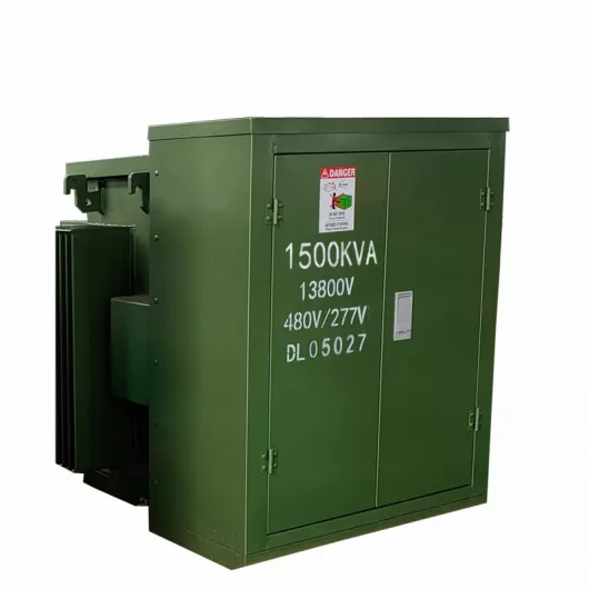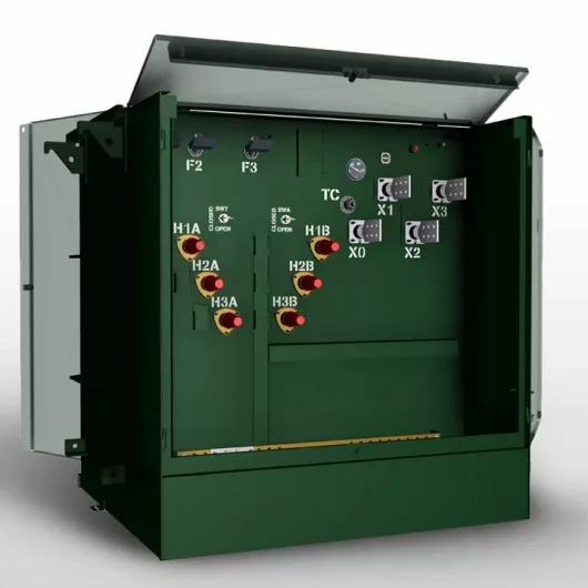
How to Choose Pad Mounted Transformer?
Table of Contents Selecting the right pad-mounted transformer requires careful consideration of several critical factors, as these ground-mounted distribution transformers play a vital role
ELECTRIC, WITH AN EDGE

When three distribution transformers are operated in parallel, why does the power factor of the distribution transformer become smaller?
My personal opinion is that the capacity of your distribution transformer is not selected according to the capacity of 3 distribution transformers in parallel.
The capacity of this parallel operation of distribution transformers is equal to the sum of their capacities.
If it is selected according to the capacity of two distribution transformers, then the parallel connection of another distribution transformer is equivalent to paralleling an inductive coil load;
If it is selected for operation with one distribution transformer capacity, it is equivalent to connecting two in parallel. Taiwan inductive load.
Then the result is that the signal acquisition through the reactive power compensation controller is completely mismatched, and of course, the display power factor becomes smaller.
First of all, we must know what is the purpose of the parallel operation of 3 distribution transformers?
There are two purposes of parallel operation of distribution transformers, one is to improve the reliability of power supply, and the other is to improve the operating efficiency of distribution transformers.
In the circuit, the cosine cosφ of the phase difference angle φ between the voltage and the current is called the power factor of the circuit.
Because the ratio of the active power P and the apparent power S is equal to the power factor cosφ, that is, cosφ=P/S and the apparent power is equal to √P2⁺Q2, so cosφ=P/S=√P2⁺Q2.
It can be seen from the above formula that the way to improve the power factor is mainly how to reduce the reactive power Q.
The loads that are often encountered in industrial production, such as asynchronous motors, AC electrical appliances, etc., are mostly inductive loads with resistance and inductance, and the power factor of this type of load is not high.
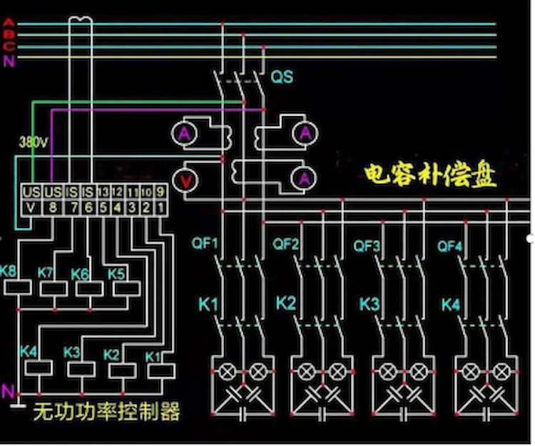
If you want to improve the power factor, you can connect appropriate capacitors in parallel at both ends of the inductive load to reduce the reactance value.
In this way, not only the power factor of the circuit can be improved, but also the current in the circuit can be reduced.
★Under normal circumstances, the capacity value (Kvar) of the compensation capacitor is generally selected according to 25~30 of the rated capacity (KVA) of the distribution transformer.
However, in actual operation, the inductive load is very random, and the dynamic range is relatively large and it is not suitable to be calculated so accurately. This causes the capacitor to be over-compensated.
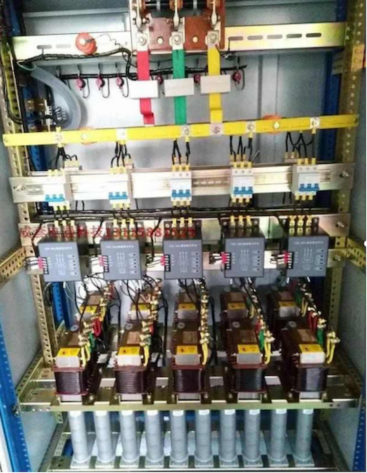
★Power factor is a very important parameter in the response power supply line or system. For example, a 10KV/0.4KV three-phase AC power distribution transformer has a rated output capacity of 100KVA, and the three-phase loads in the line are all three-phase motors (it is an inductive load, and the phase of the current in the inductive load circuit is always Lags behind the voltage, at this time 0°<φ<90°).
Before capacitor compensation is used, the power factor is generally between 0.7 and 0.85. This will cause the rated output power of the distribution transformer to drop and reach 100KvA.
The output capacity of the power supply, probably its actual capacity is in the range of about 70~85KVA so that the electrical equipment is not fully utilized.
It also increases the loss in the power supply line, so the parallel capacitor in the power supply line of the distribution transformer must be compensated to improve the power factor.
★Two or more distribution transformers are operated in parallel. When one of the distribution transformers is out of operation due to a problem, the other distribution transformers will be responsible for the power supply of this distribution transformer.
When one of the distribution transformers needs to be cleaned or overhauled in normal operation, the two distribution transformers can be connected in parallel by a tie switch, and then the distribution transformers that need to be withdrawn can be taken out of operation, so as not to affect the line Normal power supply.
The relationship curve between the efficiency of the distribution transformer and the load shows that when the iron loss of the distribution transformer is equal to the copper loss, the distribution transformer has the highest efficiency and the most economical operation.
However, the electrical load is constantly changing, and the efficiency of the distribution transformer cannot always be maintained at the highest or a constant value.
This can be achieved by operating multiple distribution transformers in parallel.
From the perspective of economic operation, parallel operation of distribution transformers must consider the active power loss and reactive power loss of the distribution transformer.
Because when the grid provides reactive power, it will also cause active power loss in the grid and distribution transformers.
Therefore, the reactive power loss is often converted into active power loss, and the economic equivalent coefficient C of reactive power is generally used for conversion (calculated at 0.1 when the system is at the maximum load and 0.06 at the minimum load).
When there are several distribution transformers operating in parallel, the calculation of the number of parallel transformers for different loads can be done as follows.
Considering the same capacity and form of distribution transformers operating in parallel, the number of distribution transformers that need to be put into operation under different load conditions can be determined according to the following formula.
When the load increases
S>Se√n(n+1)▲Po+C▲Qo/▲Pd+C▲Qd
It is more economical to invest one more of the n distribution transformers operating in parallel.
When the load decreases
S< Se√n(n-1)▲Po+C▲Qo/▲Pd+C▲Qd
It is more economical to remove one of the n distribution transformers operating in parallel.
Where S ……total load, kVA;
Se……The capacity of each press, kVA;
n……The number of distribution transformers in operation sets;
▲Po……The total active power loss at no load, KVA;
▲Qo……The total reactive power loss at no load, Kvar;
▲Pd……Total short-circuit active power loss, KVA;
▲Qd……Total short-circuit reactive power loss, Kvar;
C… The economic equivalent coefficient of reactive power.

Table of Contents Selecting the right pad-mounted transformer requires careful consideration of several critical factors, as these ground-mounted distribution transformers play a vital role

The primary function of the pad mounted transformer is to serve as a critical distribution transformer that steps down higher primary voltage from utility distribution
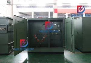
A pad mounted transformer operates through electromagnetic induction, serving as a crucial distribution component that converts high voltage electricity to lower, usable voltages for residential

When looking for the best pad-mounted transformer manufacturer, it’s important to find industry leaders known for reliability and innovative solutions. Pad-mounted transformers are essential in
