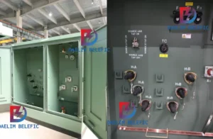
How to Choose Pad Mounted Transformer?
Table of Contents Selecting the right pad-mounted transformer requires careful consideration of several critical factors, as these ground-mounted distribution transformers play a vital role
ELECTRIC, WITH AN EDGE
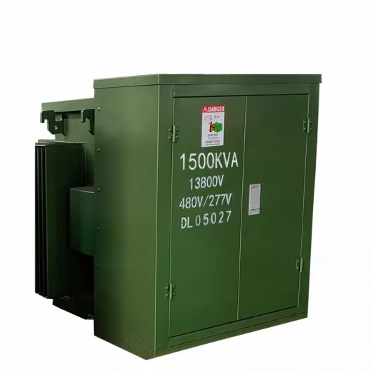
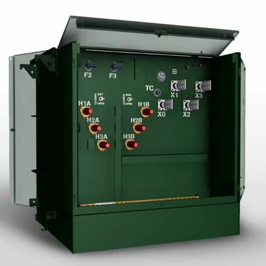
The Complete Pad-mounted Liquid Filled Compartmental Transformer Guide
There are two types of transformer windings: concentric and overlapping.
The power transformers produced in our country basically have only one structure type, namely the core transformer, so the windings are all used in a concentric structure. The so-called concentric winding means that on any cross-section of the iron core column, the windings are sleeved on the outside of the iron core column with the same cylindrical wire.
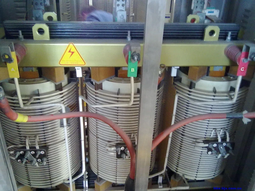
Under normal circumstances, always put the low-voltage winding inside close to the iron core, and put the high-voltage winding outside.
A certain insulation gap and heat dissipation channel (oil passage) must be left between the high-voltage winding and the low-voltage winding, and between the low-voltage winding and the iron core column, and separated by an insulating cardboard tube.
The size of the insulation distance is determined by the voltage level of the winding and the gap required by the heat dissipation channel. When the low voltage winding is placed inside and close to the iron core column, the insulation distance between it and the iron core column is relatively small, so the size of the winding can be reduced, and the overall size of the transformer is also reduced.
(a) Single-layer cylinder (b) Double-layer cylinder
Cylindrical winding
It is a cylindrical spiral body, whose turns are wound by flat wires close to each other. The cylindrical winding can be wound into a single layer; it can also be wound into a double layer. Usually try to avoid using single-layer cylinders, and instead wind into double-layer cylinders. Because when the wire is wound into a single layer, the wire is affected by elastic deformation, the coil is easy to loosen, so that the end turns are not close enough to each other; and after being wound into a double layer, the tendency to loosen is much smaller.
When the current is large, each turn is also formed by connecting several wires in parallel along the axial direction, but the number of parallel wires is usually not more than 4 to 5 wires. The cylindrical winding has the largest contact area with the cooling medium, so the cooling conditions are better, but its mechanical strength is weak, and it is generally suitable for low-voltage windings of small-capacity transformers.
(a) Shape (b) Longitudinal section wire arrangement
Spiral winding
A transformer with a larger capacity has a small number of low-voltage winding turns (20-30 turns or less), but the current is large, so the cross-section of the turns is required to be large, so many wires (6 or more) are required. Wind up in parallel. In a cylindrical winding, many wires cannot be wound in parallel, because these wires have to be wound one by one in the same layer.
As a result, the pitch of the turns is too large, and such coils are very unstable. , And the height is not well used, so it is not appropriate to use cylindrical windings when there are many parallel wires, so spiral windings appear, as shown in the figure. It is stacked and wound one by one in the radial direction. The spirals are not close to each other like a cylindrical winding, but an empty channel is left in the middle.
When the spiral winding has more wires in parallel, the wires can be divided into two groups, which becomes a double-layer spiral. When the temperature rise and insulation conditions permit, the spiral winding can adopt a structure in which oil passages of normal width and small oil passages are alternately wound. The width of the small oil passage is about half the width of the normal oil passage (about 1.5). ~2mm), so it is called a half-spiral. When the winding is a single-spiral, it is called a single-half-spiral; when the winding is a double-spiral, it is called a double-half-spiral.
This kind of semi-spiral winding has a relatively high space utilization rate and is widely used in large and medium-sized transformers.
(a) Shape (b) Longitudinal section wire arrangement
Continuous winding
The continuous winding has no welding head and can only be wound with flat wire. The turn-to-turn arrangement of the wire is as shown in the figure. It is wound through a special winding process. From one wire cake to another, the joints are alternately on the inside and outside of the coil, but they are all wound with coils. The wires are connected naturally, so there is no welding joint, which is the main advantage of continuous winding.
If the cross section of the wire is large, several wires can be wound in parallel, generally no more than 4 wires, and the positions are changed while winding.

Table of Contents Selecting the right pad-mounted transformer requires careful consideration of several critical factors, as these ground-mounted distribution transformers play a vital role
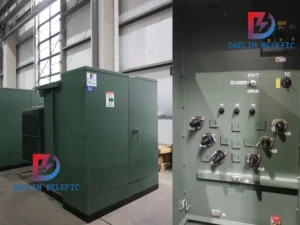
The primary function of the pad mounted transformer is to serve as a critical distribution transformer that steps down higher primary voltage from utility distribution
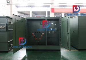
A pad mounted transformer operates through electromagnetic induction, serving as a crucial distribution component that converts high voltage electricity to lower, usable voltages for residential
When looking for the best pad-mounted transformer manufacturer, it’s important to find industry leaders known for reliability and innovative solutions. Pad-mounted transformers are essential in
After filling in the contact information, you can download the PDF.