
How to Choose Pad Mounted Transformer?
Table of Contents Selecting the right pad-mounted transformer requires careful consideration of several critical
ELECTRIC, WITH AN EDGE
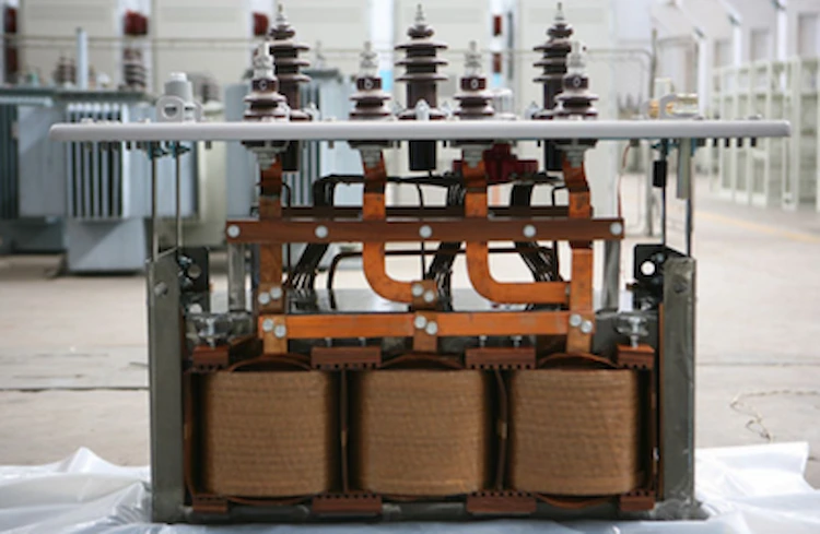
The iron transformer core is one of the most basic components of the transformer and is the magnetic circuit part of the transformer. The primary and secondary windings of the transformer are on the iron core. The iron core is usually made of 0.35 mm silicon steel sheet with surface insulation. The iron core is divided into two parts, the iron core column and the iron yoke, the iron core column is covered with windings, and the iron core is connected by the iron yoke to form a closed magnetic circuit.
In order to prevent the transformer core, clamps, pressure rings and other metal parts in operation, the induced floating potential is too high to cause discharge, and these parts need to be grounded at a single point. In order to facilitate testing and fault finding, large transformers generally lead out the iron core and the clamp through two bushings to ground.
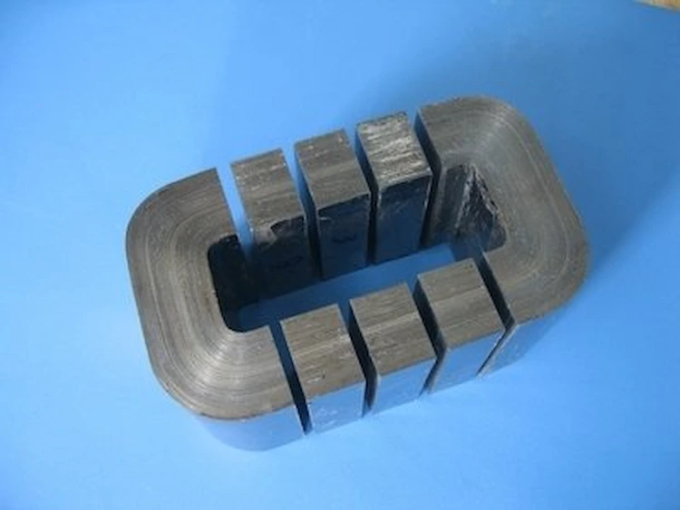
When overhauling the transformer, after opening the upper cover, you will find the iron core column stacked by many silicon steel sheets.
First of all, the transformer is made according to the principle of electromagnetic induction.
There is no electrical connection between the primary and secondary windings of a double-winding or three-winding transformer, and they are connected by magnetic flux φ.
According to the induced potential in the primary and secondary windings, it is proportional to the number of turns W1 and W2, the magnetic flux φ and its changing frequency f. The number of turns of the transformer windings cannot be infinitely wound, and it is also very uneconomical. The frequency of China’s power grid is 50Hz. Therefore, it is necessary to adjust the φ value within a suitable range.
In the circuit with more magnetic flux φ, like the basic circuit, Ohm’s law is also satisfied.
Um=φRm
In the formula, Um…magnetic circuit magnetic pressure, A;
φ……magnetic flux of magnetic circuit, wb;
Rm…magnetic circuit reluctance, A/Wb.
The magnetic pressure Um in the magnetic circuit is determined by the product of the number of turns of the primary winding and the excitation current, also called the magnetic potential.
It can be seen from the formula that if a certain value is maintained, Um is proportional to Rm, that is, the excitation current is proportional to the magnetic circuit reluctance.
The smaller the magnetic circuit reluctance, the smaller the excitation current.
Because the reluctance of ferromagnetic materials is only a few thousandths of air, or even tens of thousands of times, an iron core must be used in the transformer.
This can not only reduce the volume of the transformer, but also improve the efficiency of the transformer.
In addition, if the transformer is not equipped with an iron core, the magnetic flux leakage will be particularly large, and a lot of the magnetic flux of the primary winding will not pass through the secondary winding, which will deteriorate the load characteristics of the transformer and the load voltage drop will become large.
Therefore, it is necessary to use an iron core in the transformer.
1. Common transformer cores are usually made of ferrite cores. Silicon steel is this kind of steel that combines silicon (silicon is also called silicon), and its silicon content is 0.8 to 4.8%.
The transformer core of the transformer is made of silicon steel. Since the silicon steel itself is a magnetic chemical substance with strong magnetic working ability, in the plug-in electromagnetic coil, it can cause a large magnetic induction intensity, which can make the transformer. volume is reduced.
It is understood that the specific transformer has been working under the condition of communication and exchange, and the output power loss is not only caused by the resistor of the electromagnetic coil, but also caused in the transformer core under the magnetization of the alternating current.
Generally, the output power loss in the transformer core is called “iron loss”. The iron loss is caused by two reasons, one is “hysteresis loss” and the other is “eddy current loss”.
2. Hysteresis loss is the iron loss caused by the existence of hysteresis in the whole process of magnetization of the transformer core. The size of this loss is proportional to the size of the total area surrounded by the hysteresis loop of the raw material.
The hysteresis loop of silicon steel is narrow, and the hysteresis loss of the transformer core using it as a transformer is small, which can greatly reduce its hot level.
Now that silicon steel has the above advantages, why not need a whole piece of silicon steel to make a transformer core, but also to process it into a block?
This is due to the ability of the bulk transformer core to reduce another such iron loss – “eddy current losses”.
When the transformer is working, there is an alternating current in the electromagnetic coil, and the magnetic flux caused by it may change alternately. This shifting magnetic flux induces currents in the transformer core.
The induced current in the iron core of the transformer circulates in the plane of the vertical bisecting magnetic flux azimuth, so it is called a vortex.
Eddy current losses also make the transformer core hot.
In order to reduce the eddy current loss, the transformer core of the transformer is folded with the ferrite core of the mutual insulating layer, so that the vortex is in the slender control loop.
According to the smaller cross section, to expand the resistor on the vortex channel; at the same time, the silicon in the silicon steel expands the resistance of the raw material, and also has the effect of reducing the vortex.
3. The transformer core used as a transformer usually adopts a cold-rolled ferrite core with a thickness of 0.35mm. According to the required specifications of the transformer core, it is cut into pieces, and then stacked into a “Japanese” shape or “mouth” font.
In general, if the vortex is reduced, the thinner the ferrite core, the narrower the patchwork, and the higher the actual effect.
This not only reduces eddy current losses, reduces temperature, but also saves materials for ferrite cores. In fact, when making a ferrite core transformer core.
Not only from the above-mentioned beneficial factors, but also because of making the transformer core in this way, the comprehensive man-hours are greatly increased, and the reasonable cross-section of the transformer core is also reduced.
Therefore, when using a ferrite core to make a transformer core, it is necessary to proceed from the details, stop the loss in time, and select the best specifications.
4. The transformer is made according to the basic principle of electromagnetism. There are 2 windings, 1 primary winding, and 1 secondary winding around the closed transformer core.
When the original winding fakes the AC working voltage.
There is an alternating current flowing in the original Rao group, and a magnetic potential is created. Under the effect of the magnetic potential, the main magnetic flux of the transformer core is alternately changed, and the main magnetic flux crosses and links together in the transformer core.
Re-winding and closing because the electromagnetic effect is the same, and the re-winding causes induced electromotive force.
Why it can be pressed, and will be pressed.
You must use Lenz’s law to express. The magnetic flux caused by the induced current always blocks the transformation of the circular magnetic flux. When the original magnetic flux is raised, the magnetic flux caused by the induced current is reversed from the original magnetic flux.
That is, the magnetic induction magnetic flux caused by the re-winding is reversed with the main magnetic flux caused by the original winding, so a low-level alternating working voltage appears in the re-winding.
The iron core of the transformer is composed of silicon steel sheets.
In order to reduce the vortex, there is a certain grounding resistance between the sheets (usually only a few ohms to more than one hundred ohms).
The capacitor between the sheets is huge, which can be regarded as a loop in the alternating electric field.
Only a little connection in the core can only clamp the potential difference of the entire stack of transformer core laminations.
When the transformer core or its metal structure is connected at two points or about two points (more than one point), a closed control loop will be generated between the contacts, which will bond the unit magnetic flux, induce electromotive force, and form a loop , resulting in some over-temperature, destroying the transformer core.
The primary and secondary reasons for the minor faults of the transformer core are caused by two levels.
One is the poor construction technology to cause short-circuit faults, and the other is the extra connection caused by notes and external factors.
1. More types of transformer iron core connections.
(1) After the installation of the transformer is completed, the transport positioning pins on the car fuel tank cover have not been rotated back or removed, resulting in more connections.
(2) The leg plate of the transformer iron core clip is too close to the core column, and the transformer iron core lamination is tilted up for some reason, and it touches the leg plate of the clip, forming more connections.
(3) The cardboard of the insulating layer between the foot of the clip under the iron core of the transformer and the iron yoke is loose or damaged, so that the laminations at the iron yoke of the foot collide and connect.
(4) The submersible starter motor is equipped with large, medium and small transformers. The rolling bearing of the high temperature line submersible starter motor is damaged. The metal powder enters the fuel tank of the automobile and deposits on the bottom of the fuel tank of the automobile. Or the bottom of the box is connected to form a little more connection.
(5) The thermometer seat cover on the oil tank cover of the oil-immersed transformer is too long, and it collides with the upper clip or the iron yoke and the edge of the side column, resulting in a new contact.
(6) Dirty metal material has fallen into the oil tank of the oil-immersed transformer, which makes the transformer core lamination and the shell connect to form a connection.
(7) The wooden protective layer pad between the lower clip and the iron yoke steps is damp or the outline is not clean, and there is a lot of grease attached, which reduces the grounding resistance value to a temporary level, resulting in more connections.
2.When the connection is not optimistic, and it is not handled for a long time, the continuous operation of the transformer will cause the oil and winding to overheat, which will gradually embrittle the oil-paper insulation layer.
It will cause the two cable sheaths of the transformer core lamination to become brittle and fall off, which will cause the larger transformer core to overheat, and the transformer core will be destroyed.
3. Connecting for a long time will cause the deterioration of the oil-immersed aviation hydraulic oil and produce flammable gas, which is negative for the automobile relay posture of the gas.
(1) Carry out the interpretation of the gas chromatograph. In the chromatographic interpretation, if the water content of methane and olefins in the gas is high, the high temperature line and the water content of carbon monoxide and carbon dioxide do not change much from the previous analogy, or the water content is normal, it means that the transformer core is overheated, and the transformer core is overheated. Overtemperature will be a little more consequential.
(2) Measure whether there is current in the wiring. The transformer iron core can be connected to the waterproof casing and the lead wire, and the clamp meter can be used to measure whether there is current on the lead wire. When the iron core of the transformer is usually connected, it is composed of a non-current flow control loop. The amount of current on the wiring is not large, it is mAh level (usually lower than 0.4A).
When there is more than one connection, the main magnetic flux of the transformer core is equal to the short-circuit fault turns, and the circulating current passes through the turns. How many.
Usually reaching over a hundred amps. Control and measure whether there is current in the lead wire, and accurately assess whether the transformer core has more minor faults.
a. There are external wirings, and when the current is large due to minor faults, the wiring can be temporarily turned on. However, strict supervision is necessary. After the small fault points disappear, the transformer core will show a floating potential difference.
b. A little more connection is not due to the minor faults, and it is not deformed. It can be connected with a sliding line A in the wiring during operation. The selection of the sliding wire resistor is to divide the working voltage of the wiring in normal work by the online and offline current.
c. After measuring and finding the correct small fault point, if it cannot be dealt with, the transformer iron core can be moved to the same part of the small fault point during normal operation, which greatly reduces the circulating current.
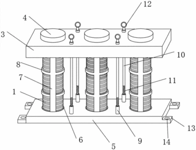
Power transformers should at least have iron cores and windings that can efficiently utilize electromagnetic induction.
The transformer windings are the core components of the transformer.
To ensure the insulation strength and specified life of the transformer body, it is necessary to maintain strong mechanical strength and a certain short-circuit strength. .
According to the requirements of the standard GB/T 6451-1999 “Technical Parameters and Requirements for Three-phase Oil-immersed Power Transformers” and the standard GB/T 16274-1996 “Technical Parameters and Requirements for Oil-immersed Power Transformers 500kV Class”, the requirements for different voltage levels and Transformer windings with different capacities have different corresponding winding methods, which have certain guiding significance for practical work.
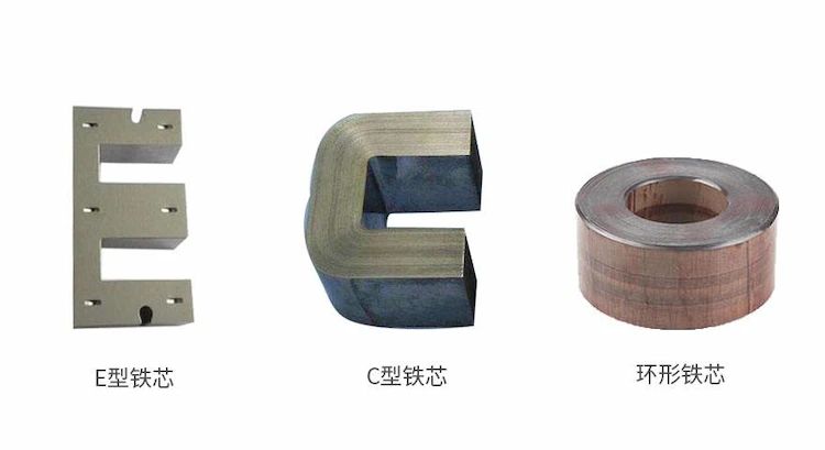
The seam methods of the iron core are divided into five types: direct seam, mixed seam (semi-straight and half-oblique), standard miter seam, step miter seam and intersecting miter seam.
The cross-sectional shapes of the core column include rectangular cross-section, involute linear cross-section, annular interface of radiating sheet, and multi-stage circular cross-section.
The section shapes of the iron yoke are rectangular section, inverted T-shaped and multi-stage inverted T-shaped section, normal T-shaped and multi-stage positive T-shaped section, multi-stage circular section and multi-pole elliptical section.
(1) Direct sewing. Direct seam means that each stack of iron core pieces is directly seamed, and the overlapping area accounts for 100% of the corner area. However, for cold-rolled grain-oriented silicon steel sheets, the larger the overlap area, the longer the magnetic flux deviates from the rolling direction, and the worse the magnetic properties, so it can only be used in hot-rolled silicon steel sheets.
(2) Hybrid seams (semi-straight and semi-mitre seams). The direct seam and the miter seam appear alternately in each stack. When the width of the stem piece and the iron yoke piece are the same, the miter seam is 450, the overlapping area accounts for 50% of the corner, and the no-load performance is significantly improved compared with the direct seam. The structural strength is reliable, the shear stacking is convenient, and the utilization rate of silicon steel sheets is the highest. But still half of it is directly seamed, which affects the further improvement of performance.
(3) Standard miter seam (with pointed miter seam). The core pieces are all 450 bevel pieces, and there are sharp corners protruding from the outside of the iron yoke (or the sharp corners are removed). There is a gap of the same size as the sharp corner on the inside of the corner, which locally improves the magnetic density and loss, the overlap area is small, the magnetic flux corner is small, the no-load performance is good, the cutting is convenient, and the utilization rate of the silicon steel sheet is high.
(4) Intersecting miter seams (variable angle seams). The angle of the seam iron core is not 450, usually 350/550 alternately overlapped, and 300/600 and 420/480 can also be used. Alternate lap joint, the joint can be joined at different angles as long as the width of the core column and the iron yoke piece are the same, but the shearing is slightly complicated and the lap area is small.
Commonly used core-type laminated cores include single-phase double-column type, single-phase side yoke type (single-phase three-column type), three-phase three-column type, and three-phase side yoke type (three-phase five-column type).
(1) Single-phase double-column laminated core. The core column and the yoke of the single-phase double-column stacked iron core are in the same plane, and they are stacked in an overlapping manner. Both columns are covered with coils, and the structure is simple.
(2) Single-phase side yoke type. The single-phase side yoke type laminated core is the same as the three-phase three-column type laminated core. In the single-phase transformer, the center column is the core column, and the two sides are the side yokes. Shell core, suitable for high-voltage large and high-voltage test transformers. In a three-phase transformer, each of the three columns is one phase, and a coil is set. It is a typical structure of a general transformer and is suitable for various three-phase transformers.
(3)Three-phase side yoke type. There are three core columns in the middle of the three-phase side yoke type laminated core, and the sections of the side yokes on both sides and the upper and lower iron yokes are about half of the core columns. Commonly used in three-phase large-capacity transformers and three-phase three-winding voltage transformers.
The iron core of a transformer can generally be divided into the following two categories.
The cross section of this type of iron core is generally rectangular, and each core column has 2 side yokes.
Since the iron core is surrounded by the winding, it is like a shell, so it is called a shell type.
The shell core has fewer chips, the core is easy to fasten, and the side iron yoke helps to reduce the additional loss caused by the leakage magnetic flux.
The shell core is also divided into single-phase and three-phase, and the three-phase shell can be regarded as composed of three independent single-phase shell transformers side by side.
The section of the core column is graded cylindrical, and the winding surrounds the core column, so it is called core type, also known as inner iron type.
This kind of iron core has many chip specifications, and requires high binding and clamping, but the winding is cylindrical, which is convenient for winding, and has good short-circuit stability, and the insulation between the winding and the iron core is also easy to handle, so it is obtained. Wide range of applications.
Because the iron core and other accessories of the transformer are in the strong electromagnetic field around the winding during operation, if they are not grounded, the iron core and other accessories will have a certain floating potential due to the action of the electromagnetic field.
Under the action of the applied voltage, when the potential difference between two points or a certain point to the ground is greater than the dielectric withstand voltage between the two, that is, when the discharge voltage is exceeded, a spark discharge will occur.
The insulating oil is decomposed or the solid insulating medium is damaged, resulting in an accident. Therefore, in order to avoid the discharge of the transformer, the core of the transformer must be grounded.
If the transformer core is grounded at multiple points, an eddy current path will be formed through the grounding point, causing local heating of the core, which is not allowed, so only one point is allowed to be grounded. In fact, although the silicon steel sheets are coated with insulating paint, their insulation resistance is small, which can only block eddy currents but cannot prevent high-voltage induced currents.
Therefore, as long as one piece of silicon steel sheets is grounded, it is equivalent to grounding the entire iron core.
Download Resource
Table of Contents Selecting the right pad-mounted transformer requires careful consideration of several critical

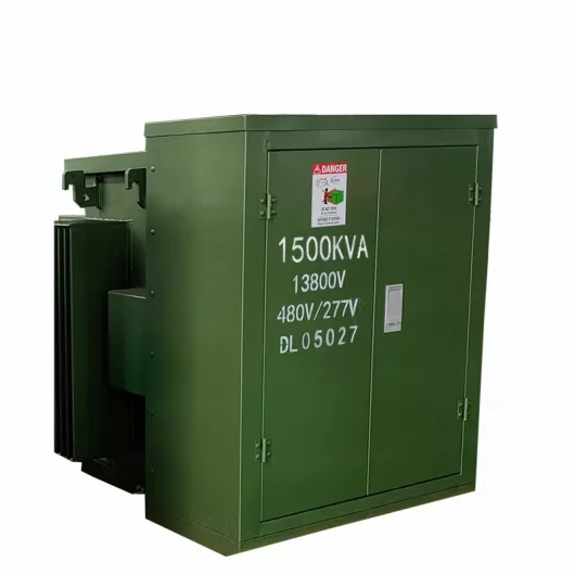
The primary function of the pad mounted transformer is to serve as a critical distribution

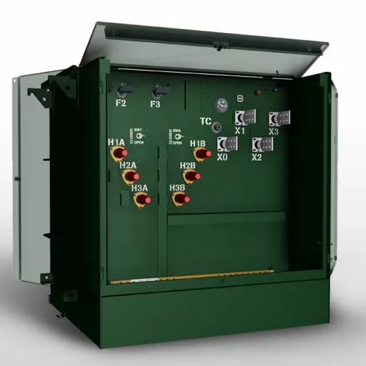
A pad mounted transformer operates through electromagnetic induction, serving as a crucial distribution component that
After filling in the contact information, you can download the PDF.