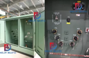
How to Choose Pad Mounted Transformer?
Table of Contents Selecting the right pad-mounted transformer requires careful consideration of several critical
ELECTRIC, WITH AN EDGE
This paper focuses on the unique use requirements of tidal energy generator set step-up transformers from three aspects: load variation, harmonics, and environmental impact, according to which the factors to be considered in the selection and design are proposed, specifically the selection and design requirements are described in detail in terms of anti-corrosion and protection, core design, harmonic voltage, and capacity.
The relevant verification calculation process of capacity selection is listed with the actual engineering data, and the impact of harmonic current and harmonic voltage on the manufacture and operation of step-up transformers is analyzed with emphasis, and finally, innovative application ideas are proposed and promoted from the perspective of energy saving and carbon reduction. It will be a general guidance and reference for tidal energy step-up transformer selection, design and manufacturing.
Daelim is a specialist manufacturer of transformers is widely praised for its speedy development and delivery. Daelim guarantees the high-quality of its transformers as well as the time of delivery. Daelim’s transformers have been certified through IEC, IEEE, ANSI, CSA, etc. and are extensively utilized across North America, South America, Europe, Australia, and so on.
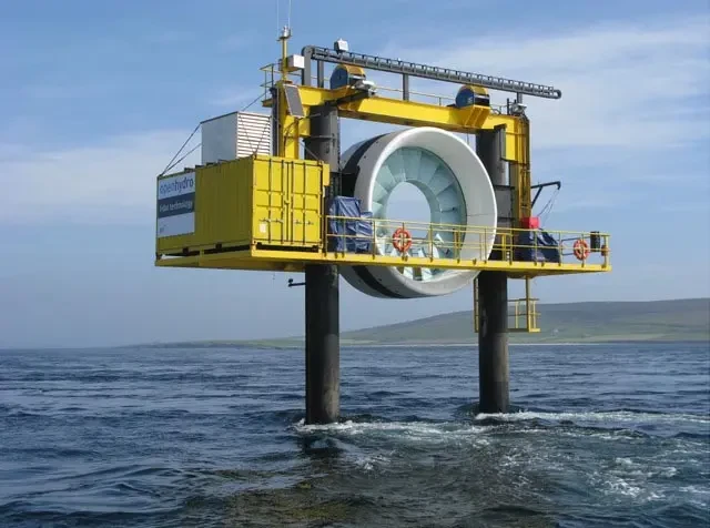
The tidal energy power generation is a new technology that uses seawater rise and fall to generate electricity. Its utilization principle is similar to that of wind power generation, both are fluid flow through the impeller to generate tangential force at the blade to drive the impeller to rotate and then drive the generator to generate electricity.
The output voltage of the tidal power generator is transformed into a stable DC voltage by PWM rectifier, and then connected to the grid by PWM inverter. The grid-side inverter is directly connected to the step-up transformer, and then the power is sent to the substation through the transmission line.
The step-up transformer plays a very important role because on the one hand it feeds the inverted power from the grid-side inverter into the grid, and on the other hand it can be used as a power source for other auxiliary equipment when the unit is not generating power. To ensure the continuous and stable operation of the step-up transformer, its selection and design are crucial.
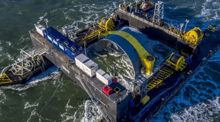
The changing tides mean that tidal energy generators are operated under a constantly changing load and the step-up transformer is subjected to multiple alternating hot and cold cycles.
In contrast to conventional distribution step-up transformers that operate under a single load, the tidal power step-up transformer can be cycled from low to high load multiple times per day as the seawater flow rate changes.
This cycling triggers repetitive thermal stresses on the windings, body and clamped structural members. The repetitive thermal stress cycles cause air to be absorbed by the hot oil and then released as the oil cools, forming tiny bubbles in the oil that transfer to the insulating members to form partial discharges or hot spots that may lead to insulation loss and aging, producing small amounts of hydrogen gas.
Multiple thermal cycles may likewise accelerate the aging triggered by the internal and external electrical connection group fittings.
Therefore, the dielectric strength, volume resistivity, heat resistance, compatibility with step-up transformer oil and other factors should be fully considered in the selection and application of step-up transformer insulation materials.
The tidal energy generator is connected to the low voltage side of the booster transformer through the converter, and after the inverter also contains high frequency components (the harmonic frequency generated by the inverter is generally in the range of 1 kHz to 4 kHz), and the output voltage and current contain harmonic components of different frequencies.
If not suppressed, it will firstly cause the total harmonic distortion rate (THD) on the converter network side to exceed the requirement of less than 5% as stipulated in GB/T25387.1-2010.
Secondly, the presence of harmonic current causes harmonic voltage drop in the line impedance.
For step-up transformers, the significant effect is that harmonic voltage will increase step-up transformer flux density, no-load loss, no-load current, noise and core temperature rise.
Again harmonic current and harmonic voltage will increase the copper loss, iron loss and eddy current loss of the step-up transformer, making the temperature of the step-up transformer rise, affecting the insulation performance and causing the capacity margin to be reduced.
At the same time, the uneven distribution of eddy current losses may cause local overheating in the winding of the step-up transformer, which affects the insulation performance. Therefore, tidal energy step-up transformer design must focus on the impact of harmonics.
The tidal power step-up transformer is installed on the offshore platform, and the operating environment is extremely harsh. Because of the salt spray in the sea air, humidity is very large, it is easy to produce corrosion on the metal parts of the step-up transformer, affecting the appearance and safe operation of the step-up transformer. Therefore, the design process must be focused on the structure and process.
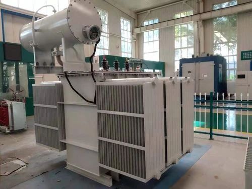
In view of the above unique requirements, tidal energy step-up transformer design should be specifically considered from the following aspects.
For step-up transformers installed on offshore platforms, the surface treatment is recommended to meet a minimum of C5-M (medium durability) corrosion protection.
For carbon steel substrates, a zinc-rich primer (epoxy or polyurethane, aliphatic or aromatic paint base) with a film thickness of not less than 60 μm is used for the base coat, and the same type of paint base with a film thickness of not less than 200 μm is used for the back coat.
For hot-dip galvanized substrates with an epoxy or polyurethane, aliphatic or aromatic base for a film thickness of not less than 60 μm and an epoxy or polyurethane, aliphatic or aromatic base type for the subsequent coating, also with acrylic paint for a film thickness of not less than 160 μm.
For parts that do not do spraying on the surface, such as valves, fasteners, etc., the material needs to meet the minimum 316L.
It should be noted that for step-up transformers with corrugated sheet radiators for the cooler, 320μm spraying is not recommended.
When the spray thickness is thicker, the adhesion is poor and the expansion of the bellows during the operation of the booster transformer can cause the bellows coating to crack.
Therefore, if higher durability requirements are required to reach C5-MH, hot-dip galvanizing treatment is recommended before painting.
The problem of poor adhesion also exists when the cooler is a sheet-type heat sink. It is also recommended that hot-dip galvanizing be followed by painting.
If the high and low voltage casing is exposed directly to the atmosphere, salt spray crystals will be attached after a long period of operation. On the one hand, such crystals can jeopardize insulation and creepage; on the other hand, they also make regular maintenance difficult and difficult to remove.
Therefore, in order to better protect the casing, a shield with a protection level of not less than IP56 can be added. The size of the shield should ensure that it meets the requirements of heat dissipation and the bending radius of the cable, and also meets the C5-M anti-corrosion standard. The sealing joint of the cable into the shield is made of brass nickel-plated glands with high anti-corrosion grade.
For the convenience of operation and maintenance, inspection windows made of Plexiglas are installed on the shield to observe the operation of the cable joints on the high and low voltage side of the booster transformer.
In addition, the high-voltage bushing can be made of fully insulated one-piece bushing, which is made of highly insulated EPDM imported rubber and produced by multi-layer compound injection process of fully automatic rubber injection equipment, featuring easy installation, waterproof, shielding and long life without exposed live parts.
Usually connected to the American T-joint, the induction point on the casing can be directly grounded or connected to a charged display indicating that the casing is charged, and is suitable for insulating oil or SF6 insulating medium. Its protection, anti-corrosion and ensure the safety of operators, compared to the porcelain casing has obvious advantages.
For tidal energy step-up transformers, the design of core flux density should consider: 1) the voltage exceeds +5% of the corresponding tap voltage, i.e., it can continue to operate at rated capacity when overexcited by 5%; 2) the presence of harmonics may lead to voltage distortion, the design should increase the consideration of 5% harmonic voltage.
Since the output of tidal power generator has typical periodicity and unevenness, the probability of the unit generating at full output is very low. Therefore, it is necessary to consider the influence of no-load loss and load loss of the step-up transformer, reasonably select the capacity of the step-up transformer, and improve its operating efficiency and economy as much as possible.
Taking the speed curve of a 1 500 kW tidal energy generator set for one day as an example, the cumulative power is generated four times a day, each time for 3 hours to 5 hours, with an interval of 2 hours to 3 hours of no-load operation.
Considering the design safety margin, the generator sets are considered at full load during the operation phase, and the output current is 1 673.5 A based on a power factor of 0.8.
Select the step-up transformer capacity according to the same installed capacity as the tidal energy power station generator set, select 1 600 kVA oil-immersed step-up transformer, calculate the allowable load: U1/U2=10/0.69, no-load loss P0 =1.64 kW (NL), load loss Pk=14.5 kW, frequency f=50 Hz, top oil temperature rise Δt1=60 K, winding average temperature rise Δt2= 65 K, core surface temperature rise limit Δt3=80 K, high voltage winding resistance per phase R=0.862 1 Ω, low voltage winding resistance per phase r=0.001 063 3 Ω.
The square root mean value of current rises to 1.000 000 5 times. At this point the resistance loss grows to 1.000 001 times, the eddy current loss grows to 1.000 07 times, and the stray loss grows to 1.000 005 times. The harmonic content is 0.10%.
Each loss component is calculated as follows:
(1) low-voltage winding
a. Loss calculation under fundamental wave current
Resistance loss PD=I2r=(1 600/1.732×0.69)2×0.001 063 3=1 905.9 W
Eddy current loss ei=PD×kw %= PD×4%=76.2 W In the formula, kw is the longitudinal eddy current loss of the winding wire in the leakage field as a percentage of the DC loss of the winding.
Total loss P = 1,905.9 W + 76.2 W = 1,982.1 W
Low voltage winding temperature rise Δt=22 K
Dissipation loss Si=rh2×h0.8=152.5 W In the formula, rh is the ratio of the hth harmonic current amplitude to the fundamental current amplitude; h is the number of current harmonics.
b. Calculation of loss under non-sine wave current
Resistance loss PD’=(1.000 000 5)2×PD=(1.000 000 5)2×1 905.9 W=1 905.902 W
Eddy current loss ei’=ei×1.000 07=76.205W
Low-voltage winding total loss P total’=1 905.902 W+76.205W=1 982.11 W
Low-voltage winding temperature rise Δt’=Δt×(P total’/P total)0.5×1.6=22 K×(1 982.11/1 982.1)0.5×1.6=22.001 K Total stray loss in operation Si’=152.5 W×1.000 005=152.501 W
(2) High voltage winding
a. Loss calculation under fundamental current
Resistance loss PD=I2R = (1 600/1.732×10)2×0.862 1=7,357 W
Eddy current loss ei=PD×kw%= PD×12%=882.8 W In the formula, kw is the longitudinal eddy current loss of the winding wire in the leakage field as a percentage of the DC loss of the winding.
Total loss P total = 7,357 W + 882.8 W = 8,239.8 W
Temperature rise of high voltage winding ΔT=23 K
Spurious loss Si= rh2×h0.8=55.2 W In the formula, rh is the ratio of the hth harmonic current amplitude to the fundamental current amplitude; h is the number of current harmonics.
b. Loss calculation under non-sine wave current
Resistance loss PD’= (1.000 000 5)2×PD = (1.000 000 5)2×7 357 W=7 357.01 W
Eddy current loss ei’=ei×1.000 07=882.8 W×1.000 07=882.9 W
Total high voltage winding loss P total’=7,357.01 W+882.9 W=8,239.91 W
High voltage winding temperature rise Δt’=Δt×(Total P’/Total P)0.5×1.6=23 K×(8 239.91/8 239.8)0.5×1.6=23.000 3 K
Total stray losses in operation Si’=55.2 W×1.000 005=55.200 3 W
This results in a step-up transformer with a reduced capacity of about 0.005‰, which can be operated without a reduced capacity. The selected 1 600 kVA step-up transformer is suitable for this operating environment and will not cause winding and oil overheating under the action of harmonic currents.
The low voltage side of the tidal energy step-up transformer is connected to a converter, which outputs a non-sinusoidal voltage signal due to the electronic circuitry. After Fourier decomposition, it will contain certain components of higher harmonics.
If the design magnetic density is too high or the harmonic voltage is too high, the high harmonics may lead to flux saturation and cause the core of the booster transformer to overheat and destroy the insulation.
Therefore, when ordering or designing, the converter manufacturer is required to provide a report on the harmonic voltage, which is taken into account when designing the step-up transformer.
It should be noted that because the flux density of a step-up transformer is the integral of voltage over time, the flux density component of each harmonic varies inversely with the number of harmonics.
We assume an inverter output voltage harmonic content, where the fundamental is 100%, the 3rd harmonic 5%, and the 5th harmonic 7%, to simulate the voltage and flux waveforms of the step-up transformer.
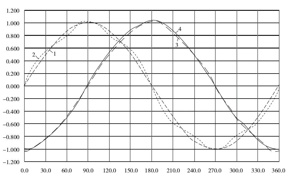
As can be seen in Figure 2, the amplitude of the magnetic induction intensity has become 1.031 times that of the magnetic induction intensity at a sinusoidal voltage, so the magnetic induction intensity should be reduced in the design.
At the same time, the waveform of magnetic induction intensity with high harmonics is smoother compared to the voltage waveform with high harmonics, indicating that this effect is suppressed (since the magnetic flux density is the integral of voltage for time).
Mineral oil is currently used more on oil-immersed step-up transformers because of its low procurement cost and good heat dissipation properties. However, mineral insulating oil is a non-renewable resource, which can neither meet the high fire performance requirements nor cause pollution to the environment.
Compared with traditional mineral oil, vegetable insulating oil is a kind of high ignition point, environmentally friendly, renewable liquid insulating medium, with ignition point higher than 300℃ and natural degradation rate of more than 90%.
Because vegetable oil is a renewable resource extracted from plant seeds, it can effectively reduce carbon emission compared with mineral oil. In addition, vegetable insulating oil has good moisture resistance, dielectric properties and hydrophilicity (able to absorb water from the solid insulating material of step-up transformers).
Therefore, the use of vegetable oils can be preferred in the design of tidal energy step-up transformers to improve the environmental friendliness. However, the difference in cost of vegetable oil compared to mineral oil needs to be evaluated.
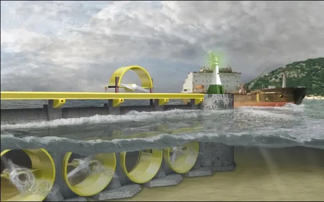
Silicone rubber is an elastic material that does not crack and is inherently non-combustible. Using high-strength silicone rubber as the main filling and encapsulating material to make dry-type step-up transformers has the characteristics of high safety and reliability, overload resistance, anti-pollution and high environmental protection. The design principle and process are as follows.
1) Liquid high performance silicone rubber casting and curing process is developed to fill and encapsulate the multi-cake high voltage winding to ensure no partial discharge inside the high voltage winding, and the high voltage winding is dustproof and moisture-proof.
The interior of the high-voltage winding adopts compact multi-segment continuous winding design, and the voltage between cakes is strictly designed using Paxing’s law to reliably meet the principle of air non-discharge, completely eliminating the hidden problem of local discharge inside the wire package.
The dynamic insulation principle is applied outside the high-voltage winding to form a double layer of solid insulation material + air combination insulation; the comb-free structure is used to enhance the lightning impact performance.
(2) low-voltage winding is wound and cured by copper foil and H-level prepreg insulation material together, with a high-strength outer envelope insulation layer, which can withstand high-current impact during short-circuit and prevent high-voltage intrusion.
(3) The anti-flash casing type outlet is casted into one with the body.
4)The core adopts high quality low-loss cold-rolled oriented silicon steel strip, which is automatically sheared and automatically stacked by high-precision equipment to ensure that the no-load loss and no-load current meet the design requirements.
Combined with the unique requirements of tidal energy step-up transformer, silicone rubber step-up transformer has the following satisfying points.
(1) The insulation system of silicone rubber step-up transformer is designed according to the heat resistance class H (180℃), while the silicone rubber insulation material itself belongs to class C insulation material withstanding temperature up to 220℃, which can meet the possible overload of the step-up transformer during the astronomical tide, while greatly slowing down the aging of the insulation system and prolonging the service life.
(2) tidal energy step-up transformer has a long no-load period, the annual average load rate is basically 35% or less. Therefore, minimizing no-load losses is of great economic importance to reduce the cost of power generation.
Silicon rubber step-up transformer design in the core and coil insulation safety premise using pie type coil structure can reduce the coil volume, while reducing the three-phase coil spacing to reduce the core center distance, due to the existence of the pie type coil structure and the use of high-strength insulation technology and tying process makes the entire coil structure is very compact, and thus the full height of the core is reduced, so that the magnetic circuit is shortened.
The overall weight of the core becomes smaller when the magnetic circuit is shortened, and the parameters affecting the no-load loss are the total weight of the core, the unit iron loss, the process coefficient, the lamination coefficient, etc. Therefore, shortening the magnetic circuit can effectively reduce the no-load loss and achieve the energy-saving effect if other parameters remain unchanged.
For example, the no-load loss of the above 1 600 kVA oil transformer is 1 640 W and the load loss is 14 500 W, while the no-load loss of the silicone rubber booster transformer of the same capacity can reach 1 415 W ~ 1 665 W and the load loss can reach 11 320 W, which has obvious energy-saving advantages.
(3) Can be used in the environment in salt spray, mold, humidity and heat and many other harsh weather climates. Specially developed dry type step-up transformer for outdoor use at sea, three anti-treatment for the exposed metal parts such as clamped parts and core of step-up transformer.
The fully encapsulated structure and H-class insulation system are suitable for use in such harsh environments at sea.
(4) tidal energy generator sets are located in the sea, the traffic has limitations, maintenance or maintenance need to invest a large amount of manpower and material resources, and failure, because of the longer maintenance time will affect the generation capacity of the unit. The silicone rubber booster transformer is maintenance-free for the whole life cycle of 30 years as long as it is put into operation smoothly, and there is no maintenance cost later.
5) Silicone rubber step-up transformers will be higher than ordinary epoxy dry type step-up transformers and oil into a higher cost, but in the long run, there is no O&M cost, and the pollution-free recycling rate can reach 98% at the end of life. Overall the cost will not be higher than other step-up transformers, or even lower.
Download Resource

Table of Contents Selecting the right pad-mounted transformer requires careful consideration of several critical
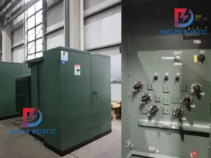
The primary function of the pad mounted transformer is to serve as a critical distribution
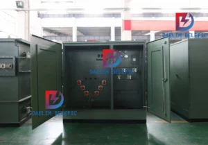
A pad mounted transformer operates through electromagnetic induction, serving as a crucial distribution component that
After filling in the contact information, you can download the PDF.