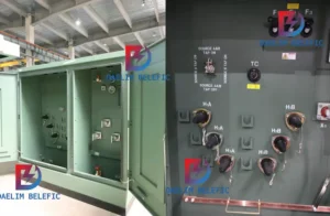
How to Choose Pad Mounted Transformer?
Table of Contents Selecting the right pad-mounted transformer requires careful consideration of several critical factors, as these ground-mounted distribution transformers play a vital role
ELECTRIC, WITH AN EDGE
The signal output of the resolver is a two-phase quadrature analog signal, and their amplitude changes with the angle of rotation, and the frequency is consistent with the excitation frequency.
Such a signal can not be directly applied, which requires an angle data conversion circuit to convert such an analog quantity into a clear angle quantity. This is the RDC (Resolver Digital converter) circuit.
There are two obvious features in digital conversion: ①In order to eliminate the change in the amplitude and frequency of the secondary output signal caused by the change in the amplitude and frequency of the excitation power supply, which will cause the angle error, the signal detection adopts the tangent method. That is to detect the ratio of the two-phase signal:, which avoids the influence of amplitude and frequency changes; ②The angle measurement is based on the principle of timely tracking and feedback. It is a fast digital servo system and belongs to a static-free system.
Most of the current applications are dedicated integrated circuits, such as R/D converters with reference oscillators.
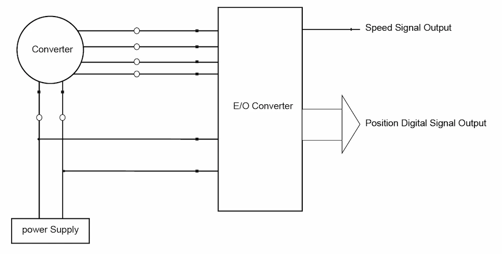
Figure 1 is a schematic diagram of the connection between the resolver and the RDC. The position signal and the speed signal are absolute signals, and their number of bits is determined by the type of RDC and actual needs. There are two types of output, serial or parallel.
The above-mentioned RDC chips can also transform the output signal into an output in the form of an encoder, that is, orthogonal A, B and Z signals per revolution. The excitation power supply is connected to the resolver and the RDC at the same time, and is used as a phase reference in the RDC.
It has become a reality to use DSP (digital signal processor) technology and software technology, instead of RDC chips, to directly use DSP to transform the position and speed of the resolver.
Using DSP to realize the decoding of resolver has some obvious advantages: ①Reduce the cost and cancel the dedicated RDC IC chip; ②Using a digital filter can eliminate the lag effect caused by speed. Use software to achieve bandwidth conversion, to compromise the relationship between bandwidth and resolution, and to make bandwidth a function of speed; ③ Stronger ability to resist environmental noise.

Table of Contents Selecting the right pad-mounted transformer requires careful consideration of several critical factors, as these ground-mounted distribution transformers play a vital role

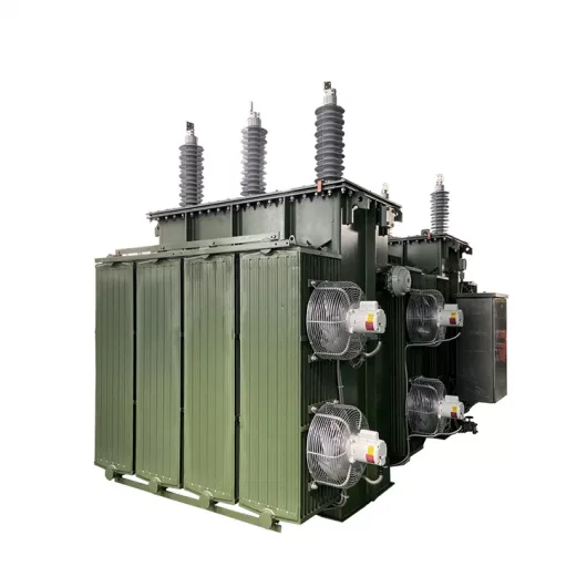
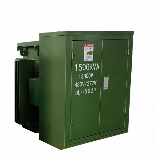
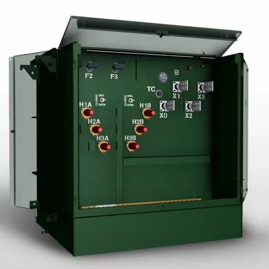
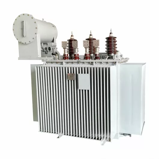
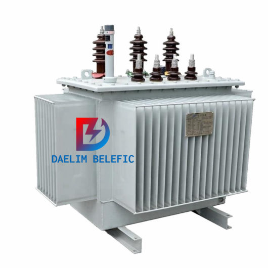
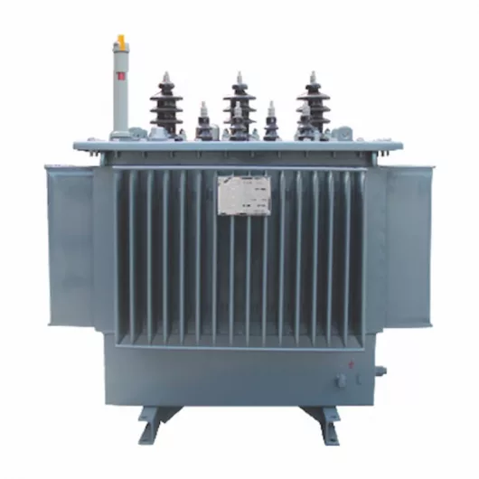
The primary function of the pad mounted transformer is to serve as a critical distribution transformer that steps down higher primary voltage from utility distribution
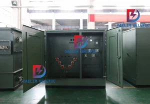
A pad mounted transformer operates through electromagnetic induction, serving as a crucial distribution component that converts high voltage electricity to lower, usable voltages for residential

When looking for the best pad-mounted transformer manufacturer, it’s important to find industry leaders known for reliability and innovative solutions. Pad-mounted transformers are essential in

After filling in the contact information, you can download the PDF.