ELECTRIC, WITH AN EDGE

Power Transformer: The Ultimate FAQ Guide

Power Transformer have been around for more than a century and as time continues to move forward, so does the advancement of transformers. In fact, the use of transformers continues to increase as the world’s population grows.

Power transformers are a type of transformer that is currently in high demand all over the world because of their many useful functions and attributes, like supplying electricity to multiple houses, regulating voltages, etc.

In this article, one of the greatest transformer manufacturers in China – DAELIM, will provide you with all the necessary information you need to completely understand what power transformers are.

But first, you should know what transformers are in general.

Power Transformer

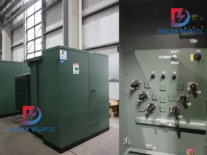
200KV Class Three Phase Two Winding OLTC/NLTC

Power Transformer

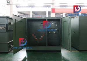
110KV Three Phase Three Winding OLTC/NLTC

Power Transformer

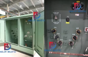
66KV Class Three Phase Two Winding OLTC/NLTC

Table of Contents

What is Transformer?

Transformers come in various sizes and shapes. There are transformers that are big as cars, and transformers that are the size of a barrel. Cooling mediums for transformers are different too.

Some transformers use pressurized air or forced air as a natural way of cooling or regulating the transformer’s temperature. Other transformers use oil as an effective way to keep temperature at moderate levels.

But regardless of the shape, size, and cooling medium, all transformers have one thing in common and that is to regulate voltages, current, or electricity in general.

Nevertheless, they are certainly not limited to that function. Transformers are used in many ways. An example of this is that it can be used to reduce voltage of conventional power circuits to operate low-voltage appliances or devices.

It can be for simple doorbells, electric stoves, microwaves, etc.

Transformers can be used to raise voltages as well from electric generators to transmit electrical power over long distances.
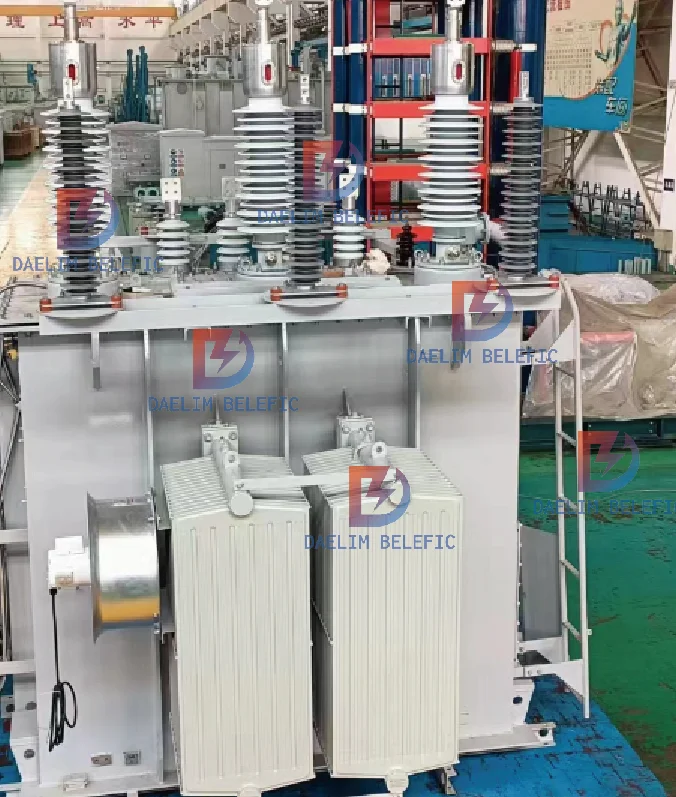
110KV Power Transformer

Transformers In A Power System

Transformers help and improve safety and efficiency of power systems stepping up (increasing) or stepping down (decreasing) voltages when needed. Transformers are used for both urban and rural areas. One of its important assets is the proper distribution and regulation of electrical power over long distances.

Transformer Principle

Most transformers work on the principle of mutual induction. Mutual induction is an occurrence that happens when the amount of magnetic flux linked with a coil charges an electromotive force that is induced in the nearest coil.

Most transformers are made up of a rectangular iron core.

Get the most complete Pad Mounted Transformer information now!

What Is Mutual Induction?

Mutual induction refers to the ability of an inductor in one circuit to induce a voltage in or to another circuit. When a transformer has alternating currents flowing in its conductor, magnetic flux will surround the conductor in proportion to the amount of the current.

What Is Magnetic Flux?

Magnetic flux is the measurement of the total magnetic field that passes through a certain or given area. This helps a lot because it describes the effects of the magnetic force on something that is occupying the given area.

The measurement of magnetic flux is associated with the certain area chosen.

What Is A Magnetic Field?

A magnetic field in transformers is considered a medium or vector field that describes the magnetic influence on flowing electricity including electric currents, electric charges, and as well as magnetic materials. Moving charges in a magnetic field will encounter a force that is perpendicular to its velocity and magnetic field.

What Is A Power Transformer?

Now that you know what a transformer is in a bigger picture, understanding power transformers will be much easier. But if there is something that you do not quite comprehend or if there is something you want to clarify after you have read everything, do not hesitate to contact DAELIM’s team of professionals for assistance.

So, what is a power transformer? To begin with, power transformers are electrical instruments that are employed to transmit power from circuit to circuit within the electromagnetic induction.

The power transfer smoothly runs without any frequency variation. In an electronic network, the power transformer’s state is applied to present a number of AC supplies of multiple voltages and compatible values of current from the public electricity support system.

It is also employed to represent the power transformers within the range of 500 kVA (kilovolt-ampere) or more.

As aforementioned, transformers are used to transmit electricity to a certain component of the electrical circuit in the range of distribution circuits and the generator that it is linked to. Power transformers are capable of doing this process, which is why power transformers are commonly utilized in distribution networks as well to adjust voltage levels.

To understand it better, here is another definition with simpler terms: power transformers convert electricity regardless if it is high or low voltage for various purposes.

In power grids, it is considered to be a major component to supply voltage to the lines that are connected. Its destination is to supply voltages to the connect lines that are connected to the power transformer.
This is why power transformers are somewhat similar to distribution transformers but it has its unique characteristics and attributes. When it comes to applications, power transformers are commonly used for transforming power from circuit to circuit without the change or disruption of frequency.

This is the basic definition of most transformers that is applicable to power transformers.Another thing that is worth mentioning is that there are no moving parts in power transformers. So, they are considered as static devices.

Power transformers only operate on an AC supply, but this does not mean that it does not work on multiple principles.

They can also be used for regulating transmission networks that are at high voltages, both stepping up and stepping down. They are commonly generated at above 200 MVA ratings.

Try for free information about the single phase pad mounted distribution transformer

What Is A Power Grid?

Power grid or power distribution grid refers to a network that delivers electricity to its consumers. Power grids involve transmission lines, distribution lines, towers, and generator stations. The generator is responsible for producing energy, converting energy into high voltage levels for distribution.

Parts Of A Power Transformer

Below is where you will find the different functions of power transformers.

Laminated core

The iron core of power transformers is usually laminated with the thin sheet. This prevents the formation of eddy currents in the core, which reduces the chance of loss of energy.
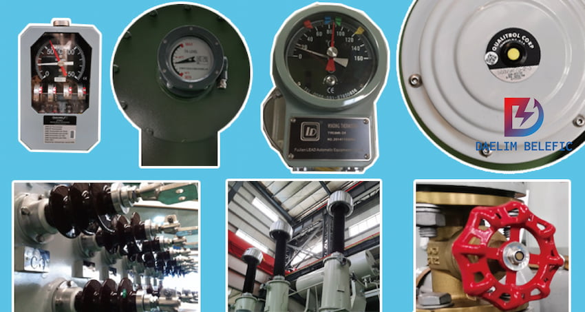
parts of power transformer

Windings

Power transformers have two windings which are the primary and secondary winding with different functions. The primary winding is responsible for drawing power from the source while the secondary winding is the coil that delivers energy at the converted voltage to the load.

Insulating materials

Power transformers have solid insulation materials, most transformers have paper press-boards and transformer boards that are formed from cellulose. Cellulose insulation with mineral oil is commonly used as the cooling medium for transformers because of its effectiveness in regulating the transformer’s temperature.

Transformer oil

Transformer oil or mineral is used as the cooling medium for transformers. Some transformers do not use oil but rather use pressurized or forced air as a natural way of cooling down the transformer.

Tap changer

Tap charger is a mechanism in power transformers and other transformers that allows variable turn ratios to be chosen in distinct steps. This process is done by connecting to a number of access points.

Keep reading: A Complete Guide to single-phase overhead conventional transformer

Oil Conservator

Oil conservators in transformers provide enough space for the increase of oil volume inside the transformer when the transformer’s temperature rises. Oil conservators can also be considered as a reservoir for insulating oil.

Breather

Breathers help prevent atmospheric moisture from coming in the transformer, which reduces maintenance costs. 

Cooling tubes

Cooling tubes include external radiator tubes that can be from air cooling installed on the transformer tank walls. The fans will suck the air from below and lead it to the top part of the tubes which cools the oil.

If the load is not full, the cooling systems can be operated without the fans.

Buchholz Relay

Buchholz relay is considered a safety device in which it is commonly used for oil-immersed transformers that are usually more than 500 kVA. Its function is to protect the transformer from faults that might occur inside the transformer.
This could be from impulse breakdowns, insulation failures, etc.

Explosion vent

Explosion vents prevent the release of excessive pressure that is generated inside the transformer.

Power Transformer Design

The design of power transformers is composed mostly of metal that is covered by stainless steel sheets. It can be either formed into a shell type or core type.

When it comes to structures, they are connected, and this emplots conductors to produce one-phase transformers or one three-phase transformers.

Three one-phase transformers will require each of its banks isolated from the extra parts, this provides the continuous service if ever one bank refuses to function properly.

For one three-phase transformer, even if it is a core type or shell type, it will simply not function.
This is why three-phase transformers is more const-effective in terms of production. It has lower carbon footprints, which is great for the environment, and better better operations with high efficiency.
Its structure is formed in a fire retardant specific fluid inside a tank. The conservatory on topenables the moving oil to cover it completely. Ther charger of the load drain the side of the tank for the best effective voltage adjustment.

When it comes to its bushings, they enable other parts of the tank to go in and out of the system without disrupting or damaging the outer shell. Power transformers are known to operate beyond low ratings.

Read my article on Types of distribution transformer

Power Transformer Working Principles

A power transformer is a static electrical device that is used to convert a certain value of AC voltage (current) into another or several different values ​​of voltage (current) with the same frequency. When the primary winding is energized with alternating current, an alternating magnetic flux is generated, and the alternating magnetic flux induces an alternating electromotive force in the secondary winding through the magnetic permeability of the iron core. The level of the secondary induced electromotive force is related to the number of turns of the primary and secondary windings, that is, the voltage is proportional to the number of turns.

The main function is to transmit electrical energy, therefore, the rated capacity is its main parameter. The rated capacity is a customary value for expressing power, which is the size of the transmitted electrical energy, expressed in kVA or MVA. When the rated voltage is applied to the transformer, it is used to determine the rated current that does not exceed the temperature rise limit under specified conditions.

The more energy-saving power transformer is the amorphous alloy iron core distribution transformer, and its biggest advantage is that the no-load loss value is extremely low. Whether the no-load loss value can be finally guaranteed is the core issue to be considered in the entire design process. When arranging the product structure, in addition to considering that the amorphous alloy core itself is not affected by external force, the characteristic parameters of the amorphous alloy must be selected accurately and reasonably during the calculation.

10kv class three-phase oil-immersed distribution transformer

Types of Power Transformer

1. Classification of power transformers by function

Power transformers are divided into two categories according to their functions: step-up transformers and step-down transformers. The factory substations all use step-down transformers.

The step-down transformer of the terminal substation, also known as the distribution transformer.

20kv class-three-phase oil-immersed distribution transformer

2. Classification of power transformers by capacity:

ower transformers are divided into two categories according to capacity series, R8 capacity series and R10 capacity series.

The R8 capacity series means that the capacity grade is increased by the multiple of R8≈1.33. The old transformer capacity grades in my country adopt this series, such as: 100kvA, 135kvA, 180kvA, 240kvA, 320kvA, 420kvA, 560kvA, 750kvA, 1000kvA, etc.

R10 capacity series means that the capacity grade is increased by multiples of R10 ≈ 1.26. The capacity level of R10 series is relatively dense, which is convenient for reasonable selection. It is recommended by IEC (International Electrotechnical Commission). my country’s new transformer capacity grades use this series, such as: 100KVA, 125kvA, 160kvA, 200kvA, 250kvA, 315kvA, 400kvA, 500kvA, 630kvA, 800kvA, 1000kvA.

3. Classification of power transformers according to the number of phases:

Power transformers are divided into two categories according to the number of phases, single-phase and three-phase. Factory substations usually use three-phase power transformers.

66kv class-three-phase two winding nltc power transformer

4. Electrical transformers are classified according to the voltage regulation method:

Power transformers are divided into two categories according to the voltage regulation mode, with no-load voltage regulation (also known as non-excitation voltage regulation) and on-load voltage regulation. Most of the factory substations use no-load voltage regulating transformers.
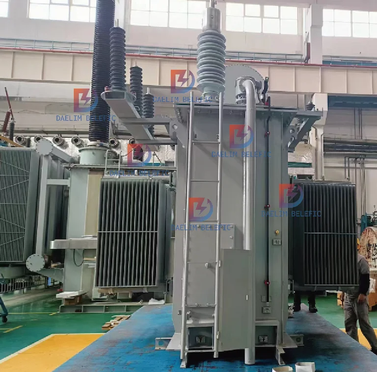
66kv class-three-phase two winding oltc power transformer

5. According to the winding structure electrical transformer:

Power transformers are divided into single-winding autotransformers, double-winding transformers, and three-winding transformers according to the winding structure. Factory substations mostly use double-winding transformers.

110kv class-three-phase three winding nltc power transformer

6. Electrical transformers are classified according to winding insulation and cooling methods:

Power transformers are classified according to winding insulation and cooling methods, including oil-immersed, dry and gas-filled (SF6). Among them, oil-immersed transformers include oil-immersed self-cooling, oil-immersed air-cooled, oil-immersed water-cooled and forced oil circulation cooling. Most of the factory substations use oil-immersed self-cooling transformers.

The so-called gas-filled transformer refers to a transformer in which the magnetic circuit (iron core) and windings of the transformer are located in a casing filled with insulating gas. In the past, SF6 gas was generally used, so it is also called a gas-insulated transformer.

110kv class three-phase three winding oltc power transformer

7. According to the winding conductor material, the electrical transformer is divided into:

Power transformers are divided into two categories according to the winding conductor material, copper winding transformers and aluminum winding transformers. Factory substations mostly used aluminum winding transformers in the past, but low-loss copper winding transformers are now more and more widely used.

What is the significance of no-load and load tests in power transformers?

The no-load and load tests of a power transformer are crucial as they help detect several performance parameters. These tests not only verify the efficiency of the transformer during actual operation but also ensure that the factory design performance meets national standards.

How does a no-load test work?

A no-load test is conducted by applying a rated voltage to one side of the winding while keeping the other winding open circuit. This test primarily checks the no-load loss and no-load current to verify whether the transformer core meets national standards and technical conditions during the design and manufacturing process.

What are the potential defects that a no-load test can detect?

A no-load test can identify design and process defects such as large local heat generation and reduced insulation in some parts of the transformer core. These defects could lead to issues like short circuits, silicon steel sheet loosening, or even possible air gap or core material damage, reducing the permeability and increasing the magnetic resistance.

What is the purpose of a load test?

A load test measures the transformer load loss and short-circuit impedance. This test is conducted by applying a test voltage to one winding, short-circuiting another winding, and keeping the rest of the winding open circuit.

How is the load loss calculated at the reference temperature?

The load loss value measured at the test temperature should be corrected to the reference temperature. The reference temperature for oil-immersed transformers is 75 °C, while for dry-type transformers, it’s generally 120 °C.

For more detailed information about power transformers, you can visit our other blogs here, here, and here.

How is the load loss at the reference temperature calculated?

The load loss value P, measured at the test temperature, should be corrected to the reference temperature. For oil-immersed transformers, the reference temperature is 75 °C, while for dry-type transformers, it’s generally 120 °C. The load loss P consists of resistance loss PR and additional loss Pw1. The correction equation for load loss at the reference temperature is given by specific formulas.

What is the short-circuit impedance calculation?

The short-circuit impedance of a transformer is divided into active and reactive components. The size of the active component is related to the temperature and needs to be corrected, while the size of the reactive component is not related to the temperature and does not need to be corrected. The percentage of active component of short-circuit impedance at tC is U., the percentage of reactive component is U., and the percentage of total short-circuit impedance is Un.

What are the potential causes of no-load loss and no-load current?

There could be several reasons for no-load loss and no-load current. These include insulation damage at the pressure plate, on the iron vantage, or other parts of the transformer, which can reduce the insulation of the core, leading to a short circuit. Other issues could be silicon steel sheet loosening, or even possible air gap or core material damage, which reduces the permeability and increases the magnetic resistance. Winding defects may also lead to inter-turn short circuits.

What precautions should be taken during a load test?

During a load test, it’s important to ensure that the test is conducted at the rated frequency and the applied current should be equal to the corresponding rated tap current. The temperature difference between the top and bottom of the oil tank should not be too large, generally not exceeding 5 K.

What is the significance of a transformer under load conditions?

A transformer under load conditions is a scenario where the transformer is operating with a load connected to it. The load loss of a transformer is a crucial parameter that is measured under these conditions. The load loss consists of resistance loss and additional loss, which includes eddy current loss and other stray losses generated by the induction potential in the conductor winding and other metal parts.

What is a Power Transformer and Why is it Important?

Power transformers are essential devices in the electrical industry, designed to step-up or step-down voltages as per the requirements of the power system. They play a pivotal role in the transmission and distribution of electricity, ensuring that power is delivered efficiently and safely.

The Role of Power Transformers

Power transformers are integral to the functioning of power systems. They are used in various stages of power transmission and distribution, converting high voltage power to lower voltages suitable for domestic and industrial use. They ensure that electricity is delivered safely and efficiently, minimizing losses and maximizing the performance of the power system.

Types of Power Transformers

There are various types of power transformers, each designed for specific applications. These include distribution transformers, power transformers, and instrument transformers. Each type has its unique features and specifications, designed to cater to different aspects of the power system.

Efficiency of Power Transformers

The efficiency of power transformers is a critical aspect of their operation. It is determined by the ratio of output power to input power. High-efficiency transformers minimize losses, thereby contributing to the overall efficiency of the power system.

Importance of Load Conditions in Power Transformers

Load conditions in power transformers are crucial as they determine the transformer’s performance and efficiency. Understanding the transformer’s behavior under no-load and full-load conditions is essential for its optimal operation and longevity.

What are the No-Load and Full-Load Conditions in a Power Transformer?

No-load and full-load conditions are critical aspects of a power transformer’s operation. The no-load condition occurs when the transformer is energized, but no load is connected to its secondary. On the other hand, the full-load condition is when the transformer is operating at its maximum capacity.

Understanding No-Load Condition

In a no-load condition, the transformer is energized, but there is no load connected to its secondary. This condition is essential for understanding the transformer’s core losses, which include hysteresis and eddy current losses.

Understanding Full-Load Condition

The full-load condition occurs when the transformer is operating at its maximum capacity. This condition is crucial for understanding the transformer’s copper losses, which occur due to the resistance of the transformer’s windings.

Impact of Load Conditions on Transformer Efficiency

The load conditions significantly impact the efficiency of the transformer. Under no-load conditions, the transformer experiences core losses, while under full-load conditions, it experiences copper losses. Minimizing these losses is crucial for enhancing the transformer’s efficiency.

Managing Load Conditions in Power Transformers

Managing load conditions in power transformers is essential for their optimal operation. This involves monitoring and controlling the load connected to the transformer, ensuring that it operates within its rated capacity to prevent overheating and potential damage.

Continue reading about the impact of load conditions on the performance and efficiency of power transformers.

How does a Transformer Behave under No-Load Conditions?

A transformer under no-load conditions is when it’s energized, but no load is connected to its secondary. This condition is crucial for understanding the transformer’s core losses, which include hysteresis and eddy current losses.

Understanding No-Load Conditions

In a no-load condition, the transformer is energized, but there is no load connected to its secondary. This condition is essential for understanding the transformer’s core losses, which include hysteresis and eddy current losses. These losses are inherent to the transformer’s operation and are present even when the transformer is not supplying any load.

Impact of No-Load Conditions on Transformer Efficiency

No-load conditions significantly impact the efficiency of a power transformer. Under no-load conditions, the transformer experiences core losses, which include hysteresis and eddy current losses. These losses are inherent to the transformer’s operation and are present even when the transformer is not supplying any load.

Managing No-Load Conditions in Power Transformers

Managing no-load conditions in power transformers is essential for their optimal operation. This involves monitoring and controlling the load connected to the transformer, ensuring that it operates within its rated capacity to prevent overheating and potential damage.

No-Load Conditions and Transformer Design

The design of a power transformer takes into account its operation under no-load conditions. The transformer’s core is designed to minimize hysteresis and eddy current losses, thereby improving its efficiency under no-load conditions.

What Happens When a Transformer is Overloaded?

Overloading a transformer means operating it beyond its rated capacity. This can lead to overheating, reduced efficiency, and potential damage to the transformer.

Understanding Transformer Overloading

Transformer overloading occurs when the load connected to the transformer exceeds its rated capacity. This can lead to excessive heat generation, which can damage the transformer’s insulation and potentially lead to a transformer failure.

Impact of Overloading on Transformer Efficiency

Overloading a transformer can significantly reduce its efficiency. The excessive heat generated due to overloading increases the transformer’s losses, thereby reducing its efficiency. Overloading can also lead to a decrease in the transformer’s lifespan.

Managing Overloading in Power Transformers

Managing overloading in power transformers involves monitoring the load connected to the transformer and ensuring that it does not exceed the transformer’s rated capacity. This can be achieved through load management strategies and the use of protective devices.

Overloading and Transformer Design

The design of a power transformer takes into account the possibility of overloading. Transformers are designed with a certain overload capacity, which allows them to handle temporary overloads without sustaining damage.

Continue reading about the impact of overloading on the performance and efficiency of power transformers.

How is Load Sharing Managed in Parallel Operation of Transformers?

Load sharing in parallel operation of transformers is a critical aspect of power system management. It ensures that the load is evenly distributed among the transformers, preventing overloading and enhancing the overall efficiency of the power system.

Understanding Load Sharing in Parallel Operation

In a power system, multiple transformers may operate in parallel to meet the power demand. Load sharing in this context refers to the distribution of the total load among these transformers. Ideally, the load should be shared proportionally to the capacity of each transformer.

Importance of Load Sharing in Power Transformers

Load sharing is crucial in power transformers for several reasons. It prevents overloading of any single transformer, thereby enhancing its lifespan and efficiency. It also allows for flexibility in power system operation, as transformers can be added or removed based on the load demand.

Factors Affecting Load Sharing in Power Transformers

Several factors can affect load sharing in power transformers. These include the capacity of each transformer, their impedance values, and the voltage at which they operate. Understanding these factors is crucial for effective load management in power systems.

Managing Load Sharing in Power Transformers

Managing load sharing in power transformers involves monitoring the load on each transformer and adjusting their operation as necessary. This can be achieved through load management strategies and the use of advanced control systems.

What is Automatic Load Sharing in Transformers?

Automatic load sharing in transformers is a technology that allows for the automatic distribution of load among transformers operating in parallel. It enhances the efficiency of the power system and prevents overloading of any single transformer.

Understanding Automatic Load Sharing

Automatic load sharing is a technology that automatically distributes the load among transformers operating in parallel. It uses advanced control systems to monitor the load on each transformer and adjust their operation as necessary.

Benefits of Automatic Load Sharing

Automatic load sharing offers several benefits. It enhances the efficiency of the power system by ensuring that no single transformer is overloaded. It also allows for flexibility in power system operation, as transformers can be added or removed based on the load demand.

Implementing Automatic Load Sharing in Power Transformers

Implementing automatic load sharing in power transformers involves the use of advanced control systems. These systems monitor the load on each transformer and adjust their operation to ensure that the load is evenly distributed.

Challenges in Implementing Automatic Load Sharing

While automatic load sharing offers several benefits, it also presents some challenges. These include the need for advanced control systems, the complexity of load management, and the need for regular maintenance and monitoring.

What is a Full Load Transformer?

A full load transformer is a transformer operating at its maximum capacity. This condition is crucial for understanding the transformer’s copper losses, which occur due to the resistance of the transformer’s windings.

Understanding Full Load Conditions

The full-load condition occurs when the transformer is operating at its maximum capacity. This condition is crucial for understanding the transformer’s copper losses, which occur due to the resistance of the transformer’s windings. These losses increase with the square of the load current, making them significant under full-load conditions.

Impact of Full Load Conditions on Transformer Efficiency

Full load conditions significantly impact the efficiency of a power transformer. Under full-load conditions, the transformer experiences copper losses, which increase with the square of the load current. These losses can significantly reduce the transformer’s efficiency if not properly managed.

Managing Full Load Conditions in Power Transformers

Managing full load conditions in power transformers is essential for their optimal operation. This involves monitoring the load on the transformer and ensuring that it does not exceed the transformer’s rated capacity. Overloading can lead to excessive heat generation, which can damage the transformer’s insulation and potentially lead to a transformer failure.

Full Load Conditions and Transformer Design

The design of a power transformer takes into account its operation under full-load conditions. The transformer’s windings are designed to handle the maximum load current, and cooling systems are often incorporated to manage the heat generated under full-load conditions.

What is the No Load Voltage of a Transformer?

The no-load voltage of a transformer is the voltage at the secondary winding when no load is connected. It is an important parameter in the design and operation of transformers.

Understanding No Load Voltage

The no-load voltage of a transformer is the voltage at the secondary winding when no load is connected. This voltage is essentially the same as the primary voltage, scaled by the turns ratio of the transformer. It provides an indication of the transformer’s voltage regulation capabilities.

Importance of No Load Voltage in Power Transformers

The no-load voltage is an important parameter in power transformers. It provides an indication of the transformer’s voltage regulation capabilities. A transformer with good voltage regulation will have a no-load voltage close to its rated voltage.

Factors Affecting No Load Voltage in Power Transformers

Several factors can affect the no-load voltage in power transformers. These include the primary voltage, the turns ratio of the transformer, and the transformer’s core losses. Understanding these factors is crucial for effective voltage regulation in power systems.

Managing No Load Voltage in Power Transformers

Managing the no-load voltage in power transformers involves monitoring the primary voltage and the load on the transformer. Adjustments to the primary voltage or the turns ratio of the transformer can be made to maintain the no-load voltage within acceptable limits.

What are the Standards for Overloading a Transformer?

Overloading a transformer means operating it beyond its rated capacity. This can lead to overheating, reduced efficiency, and potential damage to the transformer. Therefore, standards have been established to prevent transformer overloading and ensure safe and efficient operation.

Understanding Transformer Overloading Standards

Transformer overloading standards are guidelines that specify the maximum load a transformer can handle without risking damage or reduced efficiency. These standards take into account factors such as the transformer’s rated capacity, the ambient temperature, and the duration of the overload.

Importance of Overloading Standards

Overloading standards are crucial for the safe and efficient operation of power transformers. They prevent excessive heat generation that can damage the transformer’s insulation and potentially lead to a transformer failure. By adhering to these standards, the lifespan and efficiency of the transformer can be maximized.

Factors Considered in Overloading Standards

Several factors are considered in the establishment of overloading standards. These include the transformer’s rated capacity, the ambient temperature, the duration of the overload, and the cooling methods used. Understanding these factors is essential for effective load management in power systems.

Adhering to Overloading Standards

Adhering to overloading standards involves monitoring the load on the transformer and ensuring that it does not exceed the transformer’s rated capacity for an extended period. This can be achieved through load management strategies and the use of protective devices.

How is Load Sharing Achieved in Transformer?

Load sharing in transformers is achieved by operating multiple transformers in parallel and distributing the load evenly among them. This prevents overloading of any single transformer and enhances the overall efficiency of the power system.

Understanding Load Sharing in Transformers

Load sharing in transformers involves operating multiple transformers in parallel and distributing the load evenly among them. This ensures that no single transformer is overloaded, thereby enhancing its lifespan and efficiency.

Importance of Load Sharing in Transformers

Load sharing is crucial in transformers for several reasons. It prevents overloading of any single transformer, thereby enhancing its lifespan and efficiency. It also allows for flexibility in power system operation, as transformers can be added or removed based on the load demand.

Factors Affecting Load Sharing in Transformers

Several factors can affect load sharing in transformers. These include the capacity of each transformer, their impedance values, and the voltage at which they operate. Understanding these factors is crucial for effective load management in power systems.

Implementing Load Sharing in Transformers

Implementing load sharing in transformers involves monitoring the load on each transformer and adjusting their operation as necessary. This can be achieved through load management strategies and the use of advanced control systems.

Continue reading about the intricacies of load sharing in transformers.

About Daelim

Recent Posts

sbi crypto mining

What is sbi crypto mining? sbi crypto mining is a division of Japan’s SBI Holdings

About Bin Dong

Hello, I am Bin, General manager of Daelim which is a leading transformer manufacturer. If you have problems when you are looking for the equipment, what you need to do is tell us.

What is Transformer?

Transformers come in various sizes and shapes. There are transformers that are big as cars, and transformers that are the size of a barrel. Cooling mediums for transformers are different too.

Some transformers use pressurized air or forced air as a natural way of cooling or regulating the transformer’s temperature. Other transformers use oil as an effective way to keep temperature at moderate levels.

But regardless of the shape, size, and cooling medium, all transformers have one thing in common and that is to regulate voltages, current, or electricity in general.

Nevertheless, they are certainly not limited to that function. Transformers are used in many ways. An example of this is that it can be used to reduce voltage of conventional power circuits to operate low-voltage appliances or devices.

It can be for simple doorbells, electric stoves, microwaves, etc.

Transformers can be used to raise voltages as well from electric generators to transmit electrical power over long distances.

110KV Power Transformer

Transformers In A Power System

Transformers help and improve safety and efficiency of power systems stepping up (increasing) or stepping down (decreasing) voltages when needed. Transformers are used for both urban and rural areas. One of its important assets is the proper distribution and regulation of electrical power over long distances.

Transformer Principle

Most transformers work on the principle of mutual induction. Mutual induction is an occurrence that happens when the amount of magnetic flux linked with a coil charges an electromotive force that is induced in the nearest coil.

Most transformers are made up of a rectangular iron core.

Get the most complete Pad Mounted Transformer information now!

What Is Mutual Induction?

Mutual induction refers to the ability of an inductor in one circuit to induce a voltage in or to another circuit. When a transformer has alternating currents flowing in its conductor, magnetic flux will surround the conductor in proportion to the amount of the current.

What Is Magnetic Flux?

Magnetic flux is the measurement of the total magnetic field that passes through a certain or given area. This helps a lot because it describes the effects of the magnetic force on something that is occupying the given area.

The measurement of magnetic flux is associated with the certain area chosen.

What Is A Magnetic Field?

A magnetic field in transformers is considered a medium or vector field that describes the magnetic influence on flowing electricity including electric currents, electric charges, and as well as magnetic materials. Moving charges in a magnetic field will encounter a force that is perpendicular to its velocity and magnetic field.

What Is A Power Transformer?

Now that you know what a transformer is in a bigger picture, understanding power transformers will be much easier. But if there is something that you do not quite comprehend or if there is something you want to clarify after you have read everything, do not hesitate to contact DAELIM’s team of professionals for assistance.

So, what is a power transformer? To begin with, power transformers are electrical instruments that are employed to transmit power from circuit to circuit within the electromagnetic induction.

The power transfer smoothly runs without any frequency variation. In an electronic network, the power transformer’s state is applied to present a number of AC supplies of multiple voltages and compatible values of current from the public electricity support system.

It is also employed to represent the power transformers within the range of 500 kVA (kilovolt-ampere) or more.

As aforementioned, transformers are used to transmit electricity to a certain component of the electrical circuit in the range of distribution circuits and the generator that it is linked to. Power transformers are capable of doing this process, which is why power transformers are commonly utilized in distribution networks as well to adjust voltage levels.

To understand it better, here is another definition with simpler terms: power transformers convert electricity regardless if it is high or low voltage for various purposes.

In power grids, it is considered to be a major component to supply voltage to the lines that are connected. Its destination is to supply voltages to the connect lines that are connected to the power transformer.
This is why power transformers are somewhat similar to distribution transformers but it has its unique characteristics and attributes. When it comes to applications, power transformers are commonly used for transforming power from circuit to circuit without the change or disruption of frequency.

This is the basic definition of most transformers that is applicable to power transformers.Another thing that is worth mentioning is that there are no moving parts in power transformers. So, they are considered as static devices.

Power transformers only operate on an AC supply, but this does not mean that it does not work on multiple principles.

They can also be used for regulating transmission networks that are at high voltages, both stepping up and stepping down. They are commonly generated at above 200 MVA ratings.

Try for free information about the single phase pad mounted distribution transformer

What Is A Power Grid?

Power grid or power distribution grid refers to a network that delivers electricity to its consumers. Power grids involve transmission lines, distribution lines, towers, and generator stations. The generator is responsible for producing energy, converting energy into high voltage levels for distribution.

Parts Of A Power Transformer

Below is where you will find the different functions of power transformers.

Laminated core

The iron core of power transformers is usually laminated with the thin sheet. This prevents the formation of eddy currents in the core, which reduces the chance of loss of energy.

parts of power transformer

Windings

Power transformers have two windings which are the primary and secondary winding with different functions. The primary winding is responsible for drawing power from the source while the secondary winding is the coil that delivers energy at the converted voltage to the load.

Insulating materials

Power transformers have solid insulation materials, most transformers have paper press-boards and transformer boards that are formed from cellulose. Cellulose insulation with mineral oil is commonly used as the cooling medium for transformers because of its effectiveness in regulating the transformer’s temperature.

Transformer oil

Transformer oil or mineral is used as the cooling medium for transformers. Some transformers do not use oil but rather use pressurized or forced air as a natural way of cooling down the transformer.

Tap changer

Tap charger is a mechanism in power transformers and other transformers that allows variable turn ratios to be chosen in distinct steps. This process is done by connecting to a number of access points.

Keep reading: A Complete Guide to single-phase overhead conventional transformer

Oil Conservator

Oil conservators in transformers provide enough space for the increase of oil volume inside the transformer when the transformer’s temperature rises. Oil conservators can also be considered as a reservoir for insulating oil.

Breather

Breathers help prevent atmospheric moisture from coming in the transformer, which reduces maintenance costs. 

Cooling tubes

Cooling tubes include external radiator tubes that can be from air cooling installed on the transformer tank walls. The fans will suck the air from below and lead it to the top part of the tubes which cools the oil.

If the load is not full, the cooling systems can be operated without the fans.

Buchholz Relay

Buchholz relay is considered a safety device in which it is commonly used for oil-immersed transformers that are usually more than 500 kVA. Its function is to protect the transformer from faults that might occur inside the transformer.
This could be from impulse breakdowns, insulation failures, etc.

Explosion vent

Explosion vents prevent the release of excessive pressure that is generated inside the transformer.

Power Transformer Design

The design of power transformers is composed mostly of metal that is covered by stainless steel sheets. It can be either formed into a shell type or core type.

When it comes to structures, they are connected, and this emplots conductors to produce one-phase transformers or one three-phase transformers.

Three one-phase transformers will require each of its banks isolated from the extra parts, this provides the continuous service if ever one bank refuses to function properly.

For one three-phase transformer, even if it is a core type or shell type, it will simply not function.
This is why three-phase transformers is more const-effective in terms of production. It has lower carbon footprints, which is great for the environment, and better better operations with high efficiency.
Its structure is formed in a fire retardant specific fluid inside a tank. The conservatory on topenables the moving oil to cover it completely. Ther charger of the load drain the side of the tank for the best effective voltage adjustment.

When it comes to its bushings, they enable other parts of the tank to go in and out of the system without disrupting or damaging the outer shell. Power transformers are known to operate beyond low ratings.

Read my article on Types of distribution transformer

Power Transformer Working Principles

A power transformer is a static electrical device that is used to convert a certain value of AC voltage (current) into another or several different values ​​of voltage (current) with the same frequency. When the primary winding is energized with alternating current, an alternating magnetic flux is generated, and the alternating magnetic flux induces an alternating electromotive force in the secondary winding through the magnetic permeability of the iron core. The level of the secondary induced electromotive force is related to the number of turns of the primary and secondary windings, that is, the voltage is proportional to the number of turns.

The main function is to transmit electrical energy, therefore, the rated capacity is its main parameter. The rated capacity is a customary value for expressing power, which is the size of the transmitted electrical energy, expressed in kVA or MVA. When the rated voltage is applied to the transformer, it is used to determine the rated current that does not exceed the temperature rise limit under specified conditions.

The more energy-saving power transformer is the amorphous alloy iron core distribution transformer, and its biggest advantage is that the no-load loss value is extremely low. Whether the no-load loss value can be finally guaranteed is the core issue to be considered in the entire design process. When arranging the product structure, in addition to considering that the amorphous alloy core itself is not affected by external force, the characteristic parameters of the amorphous alloy must be selected accurately and reasonably during the calculation.

10kv class three-phase oil-immersed distribution transformer

Types of Power Transformer

1. Classification of power transformers by function

Power transformers are divided into two categories according to their functions: step-up transformers and step-down transformers. The factory substations all use step-down transformers.

The step-down transformer of the terminal substation, also known as the distribution transformer.

20kv class-three-phase oil-immersed distribution transformer

2. Classification of power transformers by capacity:

ower transformers are divided into two categories according to capacity series, R8 capacity series and R10 capacity series.

The R8 capacity series means that the capacity grade is increased by the multiple of R8≈1.33. The old transformer capacity grades in my country adopt this series, such as: 100kvA, 135kvA, 180kvA, 240kvA, 320kvA, 420kvA, 560kvA, 750kvA, 1000kvA, etc.

R10 capacity series means that the capacity grade is increased by multiples of R10 ≈ 1.26. The capacity level of R10 series is relatively dense, which is convenient for reasonable selection. It is recommended by IEC (International Electrotechnical Commission). my country’s new transformer capacity grades use this series, such as: 100KVA, 125kvA, 160kvA, 200kvA, 250kvA, 315kvA, 400kvA, 500kvA, 630kvA, 800kvA, 1000kvA.

3. Classification of power transformers according to the number of phases:

Power transformers are divided into two categories according to the number of phases, single-phase and three-phase. Factory substations usually use three-phase power transformers.

66kv class-three-phase two winding nltc power transformer

4. Electrical transformers are classified according to the voltage regulation method:

Power transformers are divided into two categories according to the voltage regulation mode, with no-load voltage regulation (also known as non-excitation voltage regulation) and on-load voltage regulation. Most of the factory substations use no-load voltage regulating transformers.

66kv class-three-phase two winding oltc power transformer

5. According to the winding structure electrical transformer:

Power transformers are divided into single-winding autotransformers, double-winding transformers, and three-winding transformers according to the winding structure. Factory substations mostly use double-winding transformers.

110kv class-three-phase three winding nltc power transformer

6. Electrical transformers are classified according to winding insulation and cooling methods:

Power transformers are classified according to winding insulation and cooling methods, including oil-immersed, dry and gas-filled (SF6). Among them, oil-immersed transformers include oil-immersed self-cooling, oil-immersed air-cooled, oil-immersed water-cooled and forced oil circulation cooling. Most of the factory substations use oil-immersed self-cooling transformers.

The so-called gas-filled transformer refers to a transformer in which the magnetic circuit (iron core) and windings of the transformer are located in a casing filled with insulating gas. In the past, SF6 gas was generally used, so it is also called a gas-insulated transformer.

110kv class three-phase three winding oltc power transformer

7. According to the winding conductor material, the electrical transformer is divided into:

Power transformers are divided into two categories according to the winding conductor material, copper winding transformers and aluminum winding transformers. Factory substations mostly used aluminum winding transformers in the past, but low-loss copper winding transformers are now more and more widely used.

About Daelim

Recent Posts

sbi crypto mining

What is sbi crypto mining? sbi crypto mining is a division of Japan’s SBI Holdings

About Bin Dong

Hello, I am Bin, General manager of Daelim which is a leading transformer manufacturer. If you have problems when you are looking for the equipment, what you need to do is tell us.