
ELECTRIC, WITH AN EDGE
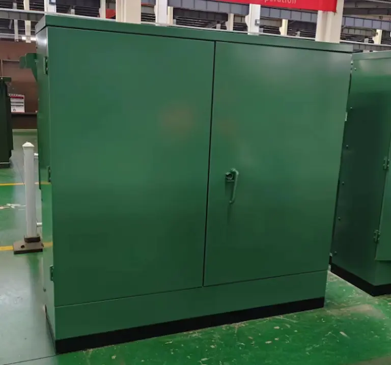
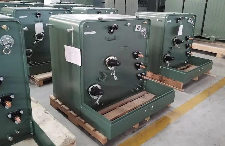
In the United States, transformer mounting pads are a vital element in modern electric distribution systems. These pads supply a tough and dependable structure for pad-mounted transformers, which are indispensable for the efficient distribution of electrical energy. Unlike pole-mounted transformers, pad-mounted transformers are mounted at ground degree and have an enclosed real estate. They are commonly made use of in both household and business locations, where they dramatically contribute to minimizing high-voltage power for functional applications.
This guide will discover different elements of transformer mounting pads, such as their functions, variations, safety and security precautions, and installation guidelines. Whether you work in the market, are a property owner curious concerning the topic, or merely have an interest in electrical systems, this guide means to use detailed information on pad-mounted transformers.
DAELIM’s selection of solitary and three phase pad mounted transformers is tailored to accommodate the differing and ever-changing electrical requirements of sectors across North America, including the USA and Canada. By integrating sophisticated modern technology with adherence to regional criteria, our transformers deliver reliable and optimum power distribution.
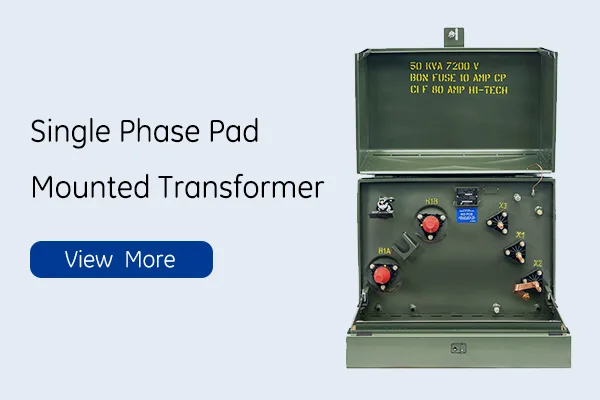

Solitary stage pad-mounted transformers are specialized electrical gadgets used largely in houses or for light industrial applications. They play a critical function symphonious down high voltage from the electric grid to useful degrees for homes and local business.
Single phase Pad mounted Transformer Specification | ||||||||
Rating (kVA) | High voltage(kV) | No Load Loss | On load Loss | Height (mm) | Depth (mm) | Width (mm) | Oil Weight(kg) | Total Weight(kg) |
15 kVA | 34.5/19.92 13.8/8 13.2/7.6 12.47/7.2 or others | 50 | 195 | 840 | 740 | 610 | 45 | 294 |
25 kVA | 80 | 290 | 840 | 740 | 610 | 68 | 362 | |
37.5 kVA | 106 | 360 | 840 | 760 | 610 | 75 | 476 | |
50 kVA | 135 | 500 | 840 | 810 | 610 | 93 | 553 | |
75 kVA | 190 | 650 | 840 | 860 | 610 | 132 | 672 | |
100 kVA | 280 | 1010 | 910 | 1200 | 965 | 230 | 714 | |
167 kVA | 435 | 1530 | 1000 | 1200 | 965 | 265 | 913 | |
250 kVA | 550 | 2230 | 1250 | 1300 | 1430 | 325 | 1106 | |
Design Characteristics:
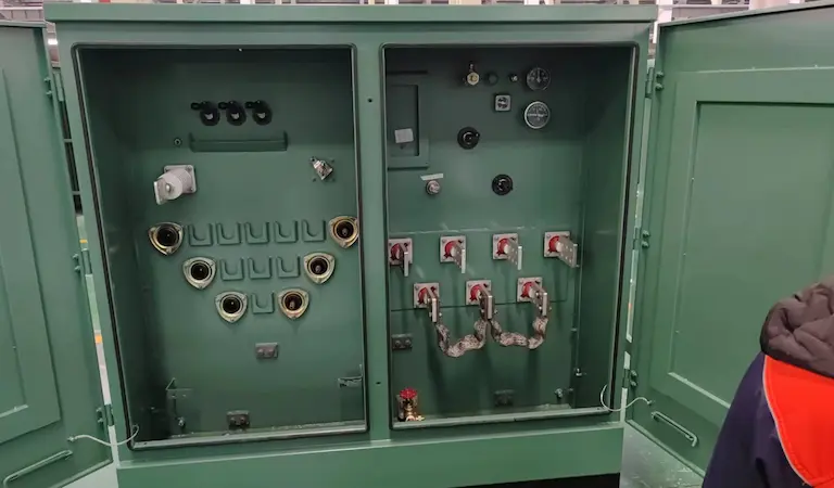
Housed in long lasting steel units that are resistant to tampering, in some cases outfitted with a lock for safety to prevent unapproved access.
Tiny in dimensions, produced to effortlessly harmonize the surroundings without drawing way too much focus aesthetically.
Consists of elements to lower sound and maintain operational sounds to a minimum.
Technical Specifications:
Voltage taking care of capabilities usually vary from 2400V to 34500V on the key side.
Standard secondary voltage outcome is 120/240V, aligning with regular residential requirements.
Dimensions and capacities differ, with a lot of systems varying as much as 500 kVA.
Safety and Compliance:
Created with safety in mind, including features like mistake security and grounding systems.
Follow industry standards such as ANSI, IEEE, and NEMA for functional safety and effectiveness.
The following table is a factory test record for Daelim 14.4 kV 100 kVA single-phase pad-mounted transformer.
Rated Capacity | 100 | Product Type | ZGD-H- 100/14.4/0.24(0.12) | 60HZ | Factory Serial No. | DL2201026 | |||||||||||
3Voltage Combination | HV(kV) | 14.4 | Current | HV | 6.94 | Polarity | Ii6 | ||||||||||
Tapping Position | HV and LVThe Voltage Value of the Test The Grade and Accuracy:QJ3 5A Grade 0.2 | HV(kV) | LV(kV) | HV/LV(%) | |||||||||||||
1 | 15120 | 240 | 0.00 | ||||||||||||||
2 | 14760 | 0.00 | |||||||||||||||
3 | 14400 | 0.00 | |||||||||||||||
4 | 14040 | 0.00 | |||||||||||||||
5 | 13680 | 0.00 | |||||||||||||||
Tapping Position | Winding Resistance Measurement | KV-HV (Ω) | LV(Ω) | ||||||||||||||
1 | 4.773 | x1x2(Ω) | 0.002009 | ||||||||||||||
2 | 4.659 | ||||||||||||||||
x2x3 (Ω) | 0.001322 | ||||||||||||||||
3 | 4.544 | ||||||||||||||||
4 | 4.432 | ||||||||||||||||
x1x3 (Ω) | 0.002972 | ||||||||||||||||
5 | 4.313 | ||||||||||||||||
The Meter NO. and Grade of Accuracy | BZC3395 Grade 0.2 | Temperature | 26℃ | Humidity | 46% | ||||||||||||
Test Items | No-Load Loss at rated voltage W | No-Load Current % | |||||||||||||||
Measured Value | 252 | 0.37 | |||||||||||||||
Test Items | Load Loss at 85°C and rated voltage W | Total Loss W | Short Circuit Impedance at 85°C | ||||||||||||||
Measured Value | 946 | 1198 | 2.61 | ||||||||||||||
Power Frequency withstand Voltage Test | x1x3Earthing | ||||||||||||||||
Test Time | 60 S | ||||||||||||||||
The Test Voltage(kV) | 10 | ||||||||||||||||
Induced Over Voltage Withstand Test | 0.48(rms) for L.V. bushing at 120HZ 60S | ||||||||||||||||
location | Insulation Resistance( M Ω) at 15℃ R60 | ||||||||||||||||
HV-E | 0 | ||||||||||||||||
LV-E | >2500 | ||||||||||||||||
Test method | Applied pressure(kPa) | Duration(h) | Residual pressure(kPa) | Result | |||||||||||||
The static pressure method | 20 | 12 | 18 | No leakage and no damage | |||||||||||||
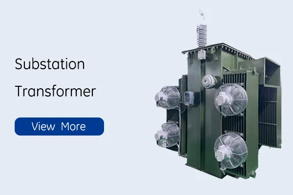
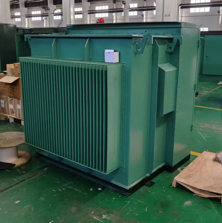
High-powered three-phase pad-mounted transformers are frequently employed in commercial and commercial settings where power needs are high. These transformers are critical for the reliable procedure of large centers, such as manufacturing facilities, office buildings, and utility business, and are made to satisfy the requirements of these demanding atmospheres.
kVA | HV | LV | Total weigh | oil weight |
75 kVA | 25000Delta | 480GrdY/277 | 1,400Kg | 540KG |
100 kVA | 24900GrdY/14400 | 600V | 729KG | 138KG |
150 kVA | 14400V | 600GrdY/347 | 2400kg | 750L |
200 kVA | 13800V | 380GrdY/220 | 2000kg | 250kg |
225 kVA | 4160Delta | 347GrdY/600V | 2500KG | 850L |
300 kVA | 34500V | 208GrdY/120 | 2300kg | 1025L |
500 kVA | 24940DELTA×12470DELTA | 208GrdY/120 | 3050kg | 1170L |
625 kVA | 13,800Delta | 480GrdY/277V | 2000KG | 520KG |
24940GrdY/14400 | 800GrdY/462 | 3100Kg | 920L | |
13,200DELTA | 480GrdY/277 | 8,360lbs | 310GAL | |
1,250 kVA | 25000V | 416V | 4000kg | 1250L |
4160GRDY/2400 | 600GrdY/347 | 4300kg | 1400L | |
1,700 kVA | 13,800Delta | 480GrdY/277V | 4600Kg | 1050L |
2,000 kVA | 4160DELTA | 415GrdY/240 | 4600Kg | 1280L |
2,500 kVA | 25000DELTA | 600GrdY/347 | 5850Kg | 1680L |
2,550 kVA | 12470DELTA | 415GrdY/240 | 5800Kg | 1750L |
2600 kVA | 34500DELTA | 416GrdY/240 | 6350Kg | 1940L |
2800 kVA | 21000V | 480V | 13669lb | 489gal |
3000 kVA | 13800V | 415V | 6700Kg | 1885L |
4000 kVA | 34,500DELTA | 12,470DELTA | 9,500Kg | 3560L |
5000 kVA | 22860GrdY/13200 | 4160GrdY/2400 | 9100Kg | 2435L |
7000 kVA | 27,600DELTA | 13,800DELTA | 11600kg | 2820L |
7500 kVA | 249400DELTA | 4.16kv Wye | 12000 Kg | 3000KG |
10000 kVA | 24900GrdY/14400 | 600V | 15000Kg | 3000L |
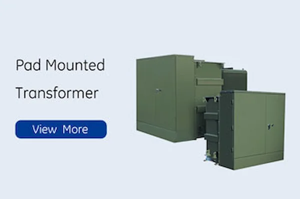
These Transformer Mounting Pads have a capability series of 75 kVA to 5000 kVA, allowing them to take care of a variety of lots needs effectively. They are developed to effectively manage power circulation in three-phase electrical systems. The pads are built with resilient, weather-resistant units to hold up against extreme environmental conditions and are outfitted with sophisticated cooling systems to take care of warm generation during operation. They also include safety and security features such as pressure relief devices and fault defense systems. These pads are available in numerous setups to fulfill certain voltage and power needs and are generally used in industries that call for a continuous power supply. They abide by rigorous safety and environmental standards and commonly consist of oil control and spill prevention systems to minimize environmental effect.
* Expected Lifespan: Pad-mounted transformers in the U.S. are normally created for a life span of 25 to 50 years. However, this can vary based on numerous variables.
Trick Factors Affecting Lifespan
* Maintenance Quality: Regular, detailed upkeep can prolong a transformer’s life substantially. For instance, a properly maintained transformer can possibly exceed its expected life-span, while ignored systems might stop working prematurely.
* Environmental Impact: Harsh ecological problems like extreme temperature levels, humidity, and contamination can accelerate aging. Transformer Mounting Pads in even more secure environments tend to last longer.
* Operational Load: Consistent procedure at or near complete capacity can lead to quicker deterioration contrasted to those used under moderate loads.
The layout and construction of pad-mounted transformers in the U.S. need to abide by strict standards developed by organizations like the American National Standards Institute (ANSI) and the Institute of Electrical and Electronics Engineers (IEEE) to ensure safety. Public precaution such as lockable rooms and indication are required to hinder unauthorized accessibility and accidents.
Rules On Proximity To Buildings
Distance laws are established by the National Electrical Safety Code (NESC) and local building and construction codes to figure out the safest distance required between a pad-mounted transformer and nearby structures. An instance of a typical requirement is a clearance of no less than 3 meters from buildings to ensure safety and security and assist in upkeep jobs.
Securing And Positioning
Safeguarding the Transformer in Place:
* Meeting Foundation Requirements: In conformity with ANSI and IEEE standards, a durable concrete structure is required to stabilize the Transformer Mounting Pad. This is vital to keep it securely repaired in position despite outside components such as wind or flooding.
* Fastening to the Pad: Properly bolting the Transformer Mounting Pad to the structure, adhering to the manufacturer’s recommendations and ANSI/IEEE standards, is crucial for guaranteeing security and security.
Security and compliance are top priorities when it pertains to placing pad-mounted transformers. To ensure safety, the National Electric Code (NEC) and neighborhood building ordinance determine details guidelines for the distance in between transformers and neighboring buildings. As an example, a common standard is maintaining a range of at least 3 meters to stop hazards and enable easy access. In addition, sufficient room around the transformer is required for risk-free and reliable maintenance and emergency situation accessibility, in accordance with OSHA (Occupational Safety and Health Administration) standards. By adhering to these standards and requirements, we can make sure the safe and effective setup of pad-mounted transformers, fulfilling the demands set by U.S. regulatory bodies.
Step-By-Step Installation Process
1. Website Preparation:
* Evaluate and prepare the setup website, making sure level ground and proper drainage.
* Determine the place based upon closeness to load factors and access for maintenance.
2. Foundation Construction:
* Construct a durable concrete foundation, following neighborhood building codes and ANSI/IEEE requirements.
* The foundation has to be of suitable measurements and deepness to sustain the weight and size of the transformer.
3. Transformer Placement and Anchoring:
* Carefully put the transformer on the concrete pad utilizing appropriate lifting equipment.
* Securely screw the transformer to the pad, guaranteeing security and alignment.
4. Electrical Connections:
* Follow supplier guidelines and NEC criteria for making electrical connections.
* Implement appropriate grounding methods as per IEEE guidelines.
5. Security and Compliance Checks:
* Conduct a comprehensive examination to ensure conformity with all pertinent safety and security criteria and guidelines.
* Verify clearances around the transformer as mandated by the NESC.
Single-Phase Pad-Mounted Transformer
1. Design and Application:
* Specifically made for property use with lower kVA ratings.
* Compact and aesthetically designed to blend into household setups.
2. Technical Specifications:
* Voltage rankings normally range from 2400V to 34500V on the key side and 120/240V on the secondary.
* Equipped with load tap changers to readjust voltage levels based on need.
3. Security Features:
* Built with lockable, tamper-proof rooms.
* Includes fault and surge protection devices.
1. Industrial and Commercial Use:
* Higher capability Transformer Mounting Pads designed for commercial and commercial applications.
* Can take care of substantial lots variants and high power demands.
2. Advanced Design Features:
* Equipped with cooling down systems for efficient warm dissipation.
* Robust construction to hold up against ecological stressors.
3. Personalization and Compliance:
* Customizable for certain voltage demands and applications.
* Compliant with rigid safety criteria like ANSI and IEEE.
1. EPA Guidelines:
* The Environmental Protection Agency (EPA) has actually developed guidelines relating to making use of hazardous compounds in transformers, consisting of restrictions on polychlorinated biphenyls (PCBs).
* For a comprehensive review of the laws, check out the EPA’s website at EPA Regulations.
2. Environmental Pollution Standards:
* Local policies usually determine environmental pollution criteria. Instances of such regulations consist of the Noise Control Act and the Quiet Communities Act, which give a framework for noise control.
* Specific requirements can be located at Noise Pollution Laws.
3. Air Conditioning and Heat Dissipation Compliance:
* ANSI/IEEE standards, such as IEEE C57.12.00 for basic requirements of transformers, define permitted temperature level surges and cooling techniques.
These requirements guarantee transformers operate within secure thermal restrictions, minimizing environmental influence. For additional information, see IEEE Standards.
1. Summary of ANSI/IEEE Standards:
* ANSI and IEEE have established standards for transformer surge and cooling techniques.
* Notable requirements are IEEE C57.12.00 (demands for liquid-immersed transformers) and IEEE C57.12.90 (testing code for liquid-immersed transformers).
2. Temperature Level Rise Requirements:
* These requirements define the maximum temperature level rise enabled transformers during regular operation.
* Temperature rise restrictions are established to keep reliability and performance, generally not exceeding 65 掳 C over ambient temperature for oil-immersed transformers.
3. Standards for Cooling Methods:
* Standards offer recommendations for various cooling down techniques, such as self-cooling, air-cooling, and liquid-cooling systems.
* The selection of a cooling method effects transformer capacity and effectiveness, with particular design factors to consider for each and every approach to make certain reliable heat dissipation.
For detailed information on these standards, industry professionals and interested parties can refer to the IEEE Standards Association website at IEEE Standards.
“Streamlining Renewable Energy Integration: Texas Unveils Comprehensive Grid Connection Guidelines”
ERCOT Standards dictate the requirements for grid connection in Texas, covering facets such as voltage levels, stage synchronization, and regularity stability. Added information can be discovered on the ERCOT website.
CAISO Regulations:
* The California Independent System Operator (CAISO) manages grid link requirements in California.
* Focuses on eco-friendly combination, voltage control, and stage balancing.
Information can be discovered at CAISO.
Florida PSC Rules:
* In Florida, the general public Service Commission (PSC) regulates transformer connections to the grid.
* Emphasizes on security, integrity, and compatibility with existing grid facilities.
* Further details is accessible at Florida PSC.
These regional guidelines highlight the importance of sticking to local energy requirements to guarantee secure and efficient grid assimilation for pad-mounted transformers.
Comprehending the specific electric codes in each state is important for the right installation and procedure of Transformer Mounting Pads. While these codes are generally lined up with the National Electrical Code (NEC), each state has its special modifications and requirements.
In the United States, various states have actually adopted their very own special electric codes, while still adhering to the standard requirements established by the National Electrical Code (NEC). California, for example, has applied the California Electrical Code (CEC), which incorporates the NEC with state-specific modifications highlighting earthquake precaution and renewable resource combination. Texas has its own Texas Electrical Code, which lines up with the NEC however consists of additional policies for severe weather conditions and energy efficiency criteria. Florida’s Florida Building Code consists of NEC standards and focuses on hurricane-resistant construction methods. Various other states, such as New York, Pennsylvania, Illinois, Ohio, Georgia, North Carolina, and Michigan, have actually additionally customized their electric codes to fit neighborhood ecological problems and power demands. It’s important for professionals mounting Transformer Mounting Pads to consult their state’s details building ordinance to make sure conformity with both nationwide and regional policies.


After filling in the contact information, you can download the PDF.