How to Choose Pad Mounted Transformer?
Table of Contents Selecting the right pad-mounted transformer requires careful consideration of several critical factors, as these ground-mounted distribution
ELECTRIC, WITH AN EDGE
In this paper, the authors will comprehensively analyze the development process of the pad mounted distribution transformer for high capacity PV inverters in the North American market according to the four main sections: external structure of the machine, principle of the electrical system, low-voltage cabinet, and oil-immersed three phase pad mounted transformer. The development process of the Pad mounted distribution transformer for PV inverter for the North American market is analyzed.
At present, the global fossil fuel reserves are depleting tremendously, and countries around the world are gradually tightening their own strategic reserves of coal, crude oil, natural gas, and so on. In the 20th century, many university scholars and industry experts have been discussing how to efficiently convert clean energy into electricity. Clean energy refers to green energy, that is, energy that does not emit pollutants and can be used directly in production and life.
Clean energy currently includes solar energy, wind energy, hydrogen energy, ocean energy, water energy, nuclear energy and other nearly ten categories, and solar energy because of its low threshold of energy access, the overall simplicity of the power generation and conversion system, a short return on investment cycle, and many other advantages, has become one of the world’s highest proportion of clean energy supply.
In May 2022, the International Energy Agency (IEA) released “Renewable Energy Market Update -Outlook for 2022 and 2023”, which mentioned that the global solar and other renewable energy power generation capacity increase in 2021 hit a new record, and with governments increasingly looking for energy security and climate benefits of utilizing renewable energy, it is expected that this will be the first time in the world that renewable energy will be utilized. This record is expected to grow further in 2022 as governments increasingly look for energy security and climate benefits from utilizing renewable energy. The report also mentions that the global new renewable power generation capacity has reached a record 295GW in 2021, and the unprecedented growth in new installations is mainly driven by solar PV installations in China, Europe and North America, etc. It is expected that the global solar power installations will continue to expand in 2022~2023.
In summary, it can be seen that in the next few years, new energy power generation technology led by solar PV will continue to develop worldwide, and both the overall installed scale and stand-alone capacity of PV power generation will continue to increase. In order to better adapt to the challenges of the international market in the future, the development of high-capacity pad mounted distribution transformer products based on the North American PV inverter market has taken on a more realistic significance.
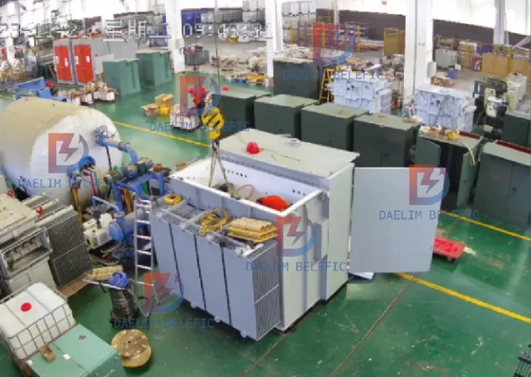
The site uses photovoltaic solar panels to generate electricity, which enters the low voltage side of the three phase pad mounted transformer through the inverter, and is then converted into voltage by the three phase pad mounted transformer and output from the high voltage side into the ring network. The developed PV inverter pad mounted distribution transformer not only takes into account the work of the inverter, but also the control tasks of the energy storage modules in the field.
The three phase pad mounted transformer has a capacity of 4500 kVA, a voltage ratio of 34.5 kV/0.8 kV, five-stage no-load voltage regulation, aluminum windings for both HV and LV, a rated operating frequency of 60 Hz, a coupling group labeled Dy1, a vegetable oil cooling medium, a cooling method KNAN, and an average winding temperature rise of ≤ 65 Kilowatt-hours. The average temperature rise of the windings is ≤65K.
The low voltage pad mounted distribution transformer needs to have both docking reservation with the inverter and control circuit reservation. In addition to providing power supply branches for the protection, measurement and control components in the low voltage room, the control branch for photovoltaic energy storage and the PLC circuit branch for inverter monitoring are also required to be reserved for on-site use.
(1) R & D target customers for the North American market, products designed and manufactured in China need to be shipped according to the export process, if the development of China’s conventional PV inverters in the form of the structure of the integrated machine, although you can make the whole machine inside the various parts of the components of the layout space is more adequate, but the problem brought about by the process of shipment pad mounted distribution Although it can make the space of each component inside the PV inverter more adequate, it brings the problem of the qualified structural strength of the pad mounted distribution transformer during transportation and the increase of the cost of export packaging.
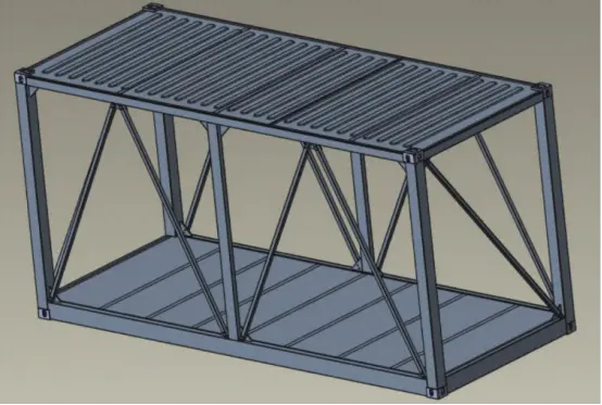
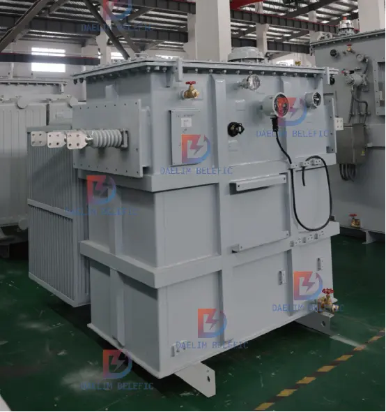
The direct use of containers as pad mounted distribution transformer shell is the most economical way, for R & D and manufacturing enterprises can save a lot of unnecessary expenditure. However, although the use of fully enclosed freight containers can fully utilize their advantages in terms of structural strength, it is difficult to achieve effective heat dissipation after the pad mounted distribution transformer is put into operation. The final solution is to dismantle the corrugated baffles around the container, and keep only the load-bearing frame as the shell of the pad mounted distribution transformer, as shown in Fig. 1.
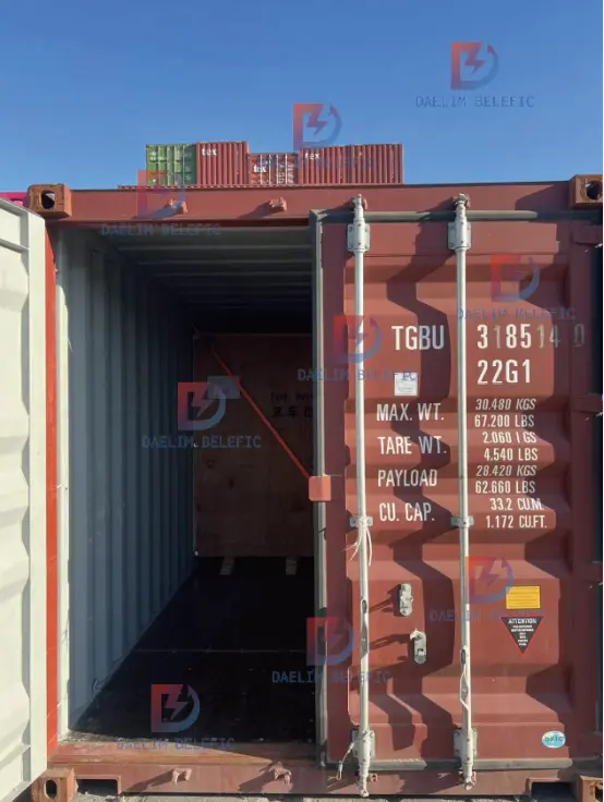
(2) Adopting variant container as the shell of pad-mounted distribution transformer, and adopting international ocean-going standard container ship transportation for transportation. After loading, pad mounted distribution transformer has standard container shell, its fixed way can be fixed according to the standard container ship stacking structure.
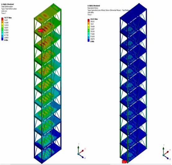
According to a large international container production and transportation group for international shipping standard container stacking management requirements, loaded container stacking stacking type for 5-4-3-2 trapezoidal layer by layer to reduce the stacking height stacking, and with nylon chemical fiber fastening belt from the side of the cross-fixed to prevent the sea transport process of bumps and rollover, as shown in Figure 2.

The whole machine primary The pad-mounted transformer diagram system is shown in Fig. 3.
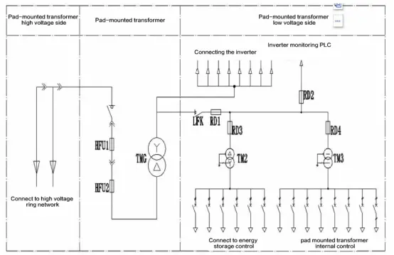
(1) Starting from the proposed demand point, the primary and secondary systems of the pad mounted distribution transformer not only have to take charge of the internal temperature and humidity control, lighting and exhaust fan measurement and protection circuits, but also need to provide the energy storage control circuit and the inverter monitoring PLC circuit. Since the working voltage level of the inverter and its monitoring PLC circuit is the same as that of the low voltage side of the three phase pad mounted transformer, both of which are 0.8kV, it is necessary to use it as a branch circuit 1; the remaining energy storage control circuit and the internal control and protection circuits can be controlled by the small dry transformer for pad-mounted distribution transformerthree phase pad mounted transformer. The remaining energy storage control circuits and internal control and protection circuits can be supplied through the small dry transformer used for control to adjust the voltage on the low-voltage side of the pad-mounted distribution transformerthree phase pad-mounted transformer to form another branch 2.
(2) Branch 1 is where the DC power output from the PV panels is converted into AC power by the inverter and fed into the low voltage side of the three phase pad mounted transformer at 0.8kV, and then boosted by the three phase pad mounted transformer to 34.5kV before being fed into the power supply loop. Since the inverter contains frame circuit breaker and branch circuit breaker for protection, the low voltage side of the pad mounted distribution transformer only needs to be connected to the copper row of the inverter, and there is no need for additional protection.
(3) The branch circuit 2 needs to be connected in parallel from the low voltage side of the three phase pad mounted transformer of the pad-mounted distribution transformer, and then through the two control circuits which control the adjustment of the three phase pad mounted transformer to 0.48kV and the energy storage control circuit and the 0.48kV control circuit of the pad mounted transformer respectively. and 0.24kV internal control circuits, respectively. This branch circuit is protected against short-circuit and overload currents by means of frame load switches and fuses. The inverter monitoring PLC circuit is directly connected to the back of the circuit and is protected by a set of fuses.
(4) The energy storage control loop turns the 0.8kV voltage into 0.48kV output through a three-phase control three phase pad mounted transformer, and the control loop turns the 0.8kV voltage into 0.24kV output through a single-phase control three phase pad mounted transformer. The energy storage and control circuits each have a set of fuses for secondary protection.
(5) The high voltage side of the system does not require additional design, because the American combined three phase pad mounted transformer has its own internal fuse and high voltage oil-immersed load switch, which can effectively protect the power transmission path between the high voltage inlet and outlet lines and the three phase pad mounted transformer body.
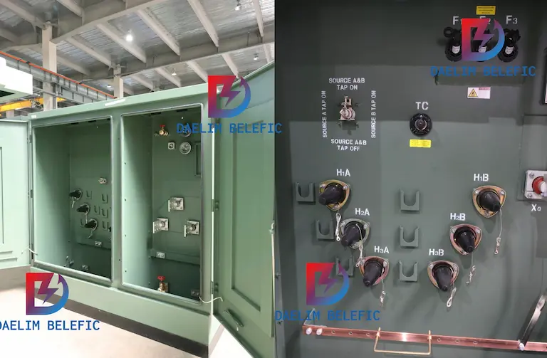
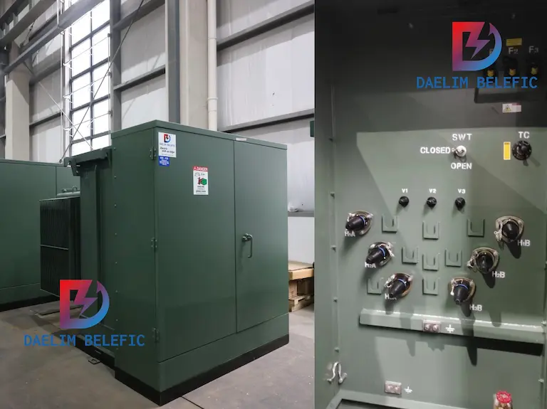
The layout of the low voltage cabinet is shown in Figure 4.
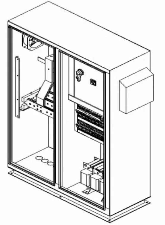
1) The shell of the low voltage cabinet is made of 2.0mm cold rolled steel plate, and the base is made of 10# channel steel or 4mm steel plate bending. Surface spraying adopts the combination of epoxy primer with a thickness of 80μm and polyurethane topcoat with a thickness of 60μm, which can play a good anti-corrosion effect.
(2) The internal arrangement is divided into two areas according to the system principle design and primary system diagram. The left half of the area is for the three phase pad mounted transformer to lead directly from the low-voltage side to the external copper rows for the use of the inverter circuit.
The right half of the area is the secondary wiring area for energy storage + control circuit, the right half of the area is divided into the upper, middle and lower layers, the upper layer is set up for the isolation load switch, the middle layer is the secondary wiring area for the control circuit, and the lower layer is placed with two dry three phase pad mounted transformer for control.
(3) The cabinet door of the low-voltage cabinet is a double-door with lever lock. The air outlet is reserved above the two side panels of the cabinet for heat exchange of the fan in the low-voltage cabinet.
(1) three phase pad mounted transformer core material using 070 grade high-performance cold-rolled silicon steel sheet, using 45 ° full six-stage seams in the form of step stacking stacked, the core is not set inside the oil channel. Stacking coefficient of 0.97, elliptical cross-section, the total number of levels is divided into 16 levels. Low-voltage upper clamp is made of 8.0mm thick non-magnetic steel plate, which can effectively reduce the eddy current loss of low-voltage upper clamp due to the proximity of low-voltage leads. High-voltage upper clamps, high-voltage lower clamps and low-voltage lower clamps are made of 16# channel steel Q235A. Upper and lower clamps and the core are set between the clip insulation.
(2) The low-voltage winding is wound with 2.2mm aluminum foil, and epoxy DMD is used as the insulating material between the layers of aluminum foil, which can withstand higher winding heat temperature. The inlet and outlet ends are led out by welded aluminum rows. The high-voltage winding is a three-section cylinder type, the wire material is paper-coated aluminum wire, and diamond-dot adhesive paper is used as the interlayer insulation between each layer of the winding, and the inter-section insulation is made by laminating the paper circle with laminated wood. A 22mm main air duct is set between the high and low voltage windings.
(3) The oil tank is made of 8.0mm hot rolled steel plate welded, with 7 sets of chip radiators in the direction of the long axis to provide the necessary heat dissipation for the whole three phase pad mounted transformer. Both sides of the short axis for the high-voltage casing and low-pressure casing respectively, high-voltage casing with the ring network with the use of a one-piece plug head casing 6, V-shaped layout, with the corresponding, as shown in Figure 5. Low-voltage casing for the porcelain bottle casing 3, horizontal arrangement.
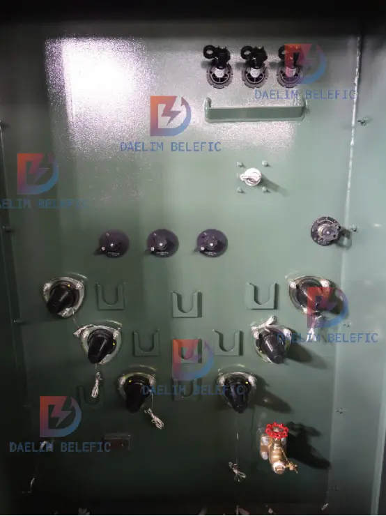
(4) The low-voltage leads are connected by 120mm×14mm aluminum rows, and the aluminum rows are connected to the low-voltage casing by copper-aluminum sheets. The high-voltage phase wires are connected with 25mm2 copper stranded wires; the high-voltage tap wires are connected with 16mm2 copper stranded wires, and the phase wires and tap wires are insulated with 3mm paper on one side. The HV phase wires are connected to the HV casing after being led out from the winding and passing through backup fuses, plug-in fuses and oil-immersed load switches.
According to the recommendation of the fuse manufacturer, it is determined that the insertion fuse is two 40A type in parallel for each phase, and the backup fuse is two 100A type in parallel for each phase.
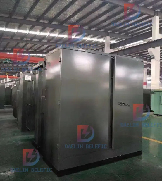
(5) There is no special structure inside the high-voltage room, which is directly connected to the high-voltage side of the three phase pad mounted transformer by flange. The three phase pad mounted transformer is shown in Fig. 6, and the pad mounted distribution transformer is shown in Fig. 7.
The measured results of the key performance parameters of the three phase pad-mounted transformer ecifications are shown in Table 1.
Test item | Standard value | Measured value | Data Conclusion |
No-load loss/W | 3300 | 3205 |
Qualified |
No-load current/% | 0.6 | 0.15 | |
Load loss (75℃)/W | 32480 | 29870 | |
Short circuit impedance (75℃)/% | 7.0 | 7.02 | |
Load loss (85℃)/W | 32480 | 30391 | |
Short circuit impedance (85℃)/% | 7.0 | 7.02 | |
Winding temperature rise (HV)/K | 65 | 51.1 | |
Winding temperature rise (LV)/K | 65 | 63.9 | |
Temperature rise of oil surface/K | 55 | 51.8 |
kVA | HV | LV | Total weigh | oil weight | |
75 kVA | 25000Delta | 480GrdY/277 | 1,400Kg | 540KG | |
100 kVA | 24900GrdY/14400 | 600V | 729KG | 138KG | |
150 kVA | 14400V | 600GrdY/347 | 2400kg | 750L | |
200 kVA | 13800V | 380GrdY/220 | 2000kg | 250kg | |
225 kVA | 4160Delta | 347GrdY/600V | 2500KG | 850L | |
300 kVA | 34500V | 208GrdY/120 | 2300kg | 1025L | |
500 kVA | 24940DELTA×12470DELTA | 208GrdY/120 | 3050kg | 1170L | |
625 kVA | 13,800Delta | 480GrdY/277V | 2000KG | 520KG | |
750 kVA | 24940GrdY/14400 | 800GrdY/462 | 3100Kg | 920L | |
1,000 kVA | 13,200DELTA | 480GrdY/277 | 8,360lbs | 310GAL | |
1,250 kVA | 25000V | 416V | 4000kg | 1250L | |
1,500 kVA | 4160GRDY/2400 | 600GrdY/347 | 4300kg | 1400L | |
1,700 kVA | 13,800Delta | 480GrdY/277V | 4600Kg | 1050L | |
2,000 kVA | 4160DELTA | 415GrdY/240 | 4600Kg | 1280L | |
2,500 kVA | 25000DELTA | 600GrdY/347 | 5850Kg | 1680L | |
2,550 kVA | 12470DELTA | 415GrdY/240 | 5800Kg | 1750L | |
2600 kVA | 34500DELTA | 416GrdY/240 | 6350Kg | 1940L | |
2800 kVA | 21000V | 480V | 13669lb | 489gal | |
3000 kVA | 13800V | 415V | 6700Kg | 1885L | |
4000 kVA | 34,500DELTA | 12,470DELTA | 9,500Kg | 3560L | |
5000 kVA | 22860GrdY/13200 | 4160GrdY/2400 | 9100Kg | 2435L | |
7000 kVA | 27,600DELTA | 13,800DELTA | 11600kg | 2820L | |
7500 kVA | 249400DELTA | 4.16kv Wye | 12000 Kg | 3000KG | |
10000 kVA | 24900GrdY/14400 | 600V | 15000Kg | 3000L |
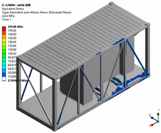
In this paper, the authors start from the background of research and development, combined with examples and related technical parameters, the pad mounted distribution transformer shell, system principle, low voltage cabinet and three phase pad mounted transformer design process has been more in-depth analysis. The mechanical simulation results of the key parts and the test data of the final samples are further verified, which provide a reference for the design and development of high-capacity pad mounted distribution transformer products for the North American market.
Table of Contents Selecting the right pad-mounted transformer requires careful consideration of several critical factors, as these ground-mounted distribution
The primary function of the pad mounted transformer is to serve as a critical distribution transformer that steps down higher
After filling in the contact information, you can download the PDF.