ELECTRIC, WITH AN EDGE
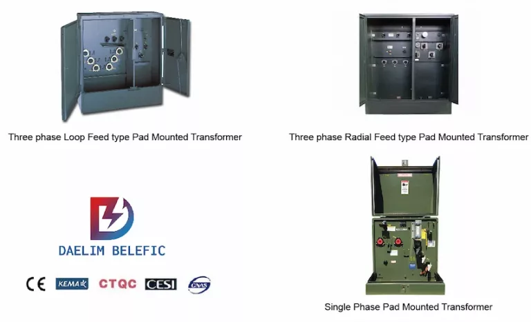
We have many questions about the Pad mounted transformer, but we can not get them from the Sales Company’s product page.
But for purchasers or engineers, we need to know more about Pad-mounted transformers in order to better buy and use it.
In this post, I will disassemble the pad-mounted transformer for you. I will also share some tips on how to choose a pad mount transformer.
The pad-mounted transformer is an important power supply equipment in the cabled distribution network.
The pad mount transformer adopts a double-fuse full-range protection method. This greatly reduces the loss.
There are mainly two types: Single-phase Pad-mounted transformer and Three-phase Pad-mounted transformer.
pad mounted transformers are a type of electrical transformer that is installed outdoors and mounted on a concrete pad. They are commonly used in residential and commercial areas to provide power for lighting, appliances, and other electrical equipment.
The pad mounted transformer works by stepping down the voltage from the main power lines to a lower voltage that is suitable for use in homes and businesses. This process is necessary because the voltage that is carried on the main power lines is too high for safe use in homes and businesses. The transformer has two sets of coils, a primary coil and a secondary coil, which are wrapped around a core of magnetic material. The primary coil is connected to the high voltage power lines, while the secondary coil is connected to the lower voltage lines that supply power to homes and businesses.
When electricity flows through the primary coil, it creates a magnetic field around the core. This magnetic field induces an electrical current in the secondary coil, which then powers homes and businesses. The transformer also has a number of safety features built-in, such as fuses, circuit breakers, and surge protection, to protect against power surges, overloading, and other electrical hazards.
Overall, pad mounted transformers are a reliable and safe way to provide power to homes and businesses. They are designed to withstand harsh weather conditions, and are regularly inspected and maintained by qualified technicians to ensure their continued safe operation.
The Pad-mounted transformer has the performance advantages of a lightweight, low noise, small size, and low loss. An excellent transformer is mainly composed of high-voltage control, protection, substation, and power distribution equipment.
The Padmounted transformer adopts the principle of parallel operation of the high-voltage side bus. Its low-voltage side bus is mainly responsible for circuit breaker transfer. It has good safety performance.
Pad-mounted transformers are widely used in large-scale business centers, railway stations, mines, and other large-scale event venues.
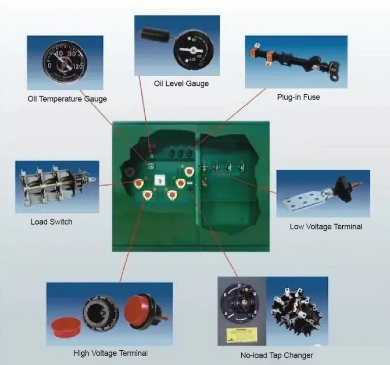
Caution: Before performing any type of service, the pressure in the fuel tank must be safely vented manually.
Caution: Do not open the Padmount Transformer in a high-humidity environment. Moisture can cause short circuits in the device.
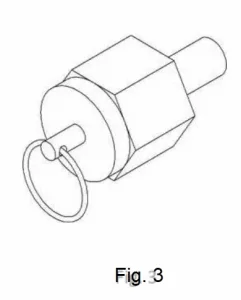
Opening the valve (Fig3) will drain the oil in the tank.
It will release the pressure in the fuel tank.
Daelim’s Padmounted transformer contains two types of valves.
One is filling the plug with the Schrader valve (Fig 4A).
The other is the filling valve with the Schrader valve (Fig. 4B).
It is used for the introduction of nitrogen and dielectric fluid.
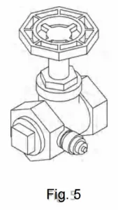
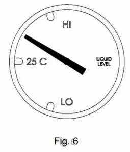
The amount of dielectric in the pad mount transformer tank can be observed with a level gauge (Fig 6).
It is magnetically coupled to the indicator needle in the gauge.
The magnetic coupling maintains the liquid seal between the inside and the outside.
It can minimize potential leakage.
Daelim uses a variety of different brands and models of level gauges according to the application.
Daelim can be equipped with standard instruments as required. If the environment is complex, more complex models can also be provided. It can facilitate external monitoring.
Under normal operation, the liquid level may change according to temperature and pressure.
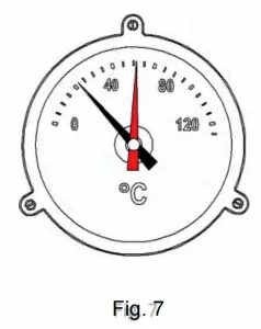
Daelim Padmount Transformer provides a thermometer (Fig 7).
Its function is to observe the temperature of the top dielectric fluid in the fuel tank.
It includes two hands, one white and one red.
The white pointer indicates the current oil temperature of the pad-mounted transformer.
The red pointer indicates the maximum reset value of the dielectric fluid temperature.
The long thermocouple is its main component.
In order to facilitate the replacement of the gauge. The thermocouple and the dielectric fluid are isolated from each other.
There are one or two SPDT alarm points on the thermometer.
It has the function of remote monitoring.
These alarms for electric shock can be set according to factory requirements.
Unscrew the small hexagonal fixing screw in the center of the meter.
It can help you adjust the contact.
Set the contacts to the required temperature. You can complete the operation.
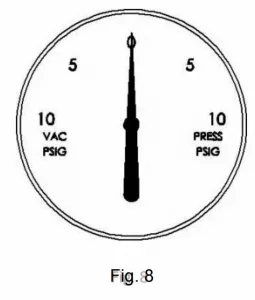
The pressure gauge (Fig 8) indicates whether the headspace pressure in the tank is positive, negative, or neutral.
The pressure change factors in the fuel tank:
The load of the device;
The temperature of the oil;
The temperature of the external environment;
The load of the device.
Padmounted transformers usually have positive or negative voltage.
Continuous low temperature will cause continuous negative pressure. It is normal.
However, if the temperature rises, the meter reading is still zero.
This means that there is a leak.
The leakage of equipment needs to be checked.
Daelim can equip the pressure gauge with SPDT alarm contacts according to your requirements.
It can remote monitoring of positive and negative pressures.
The pressure/vacuum gauge can also be equipped with a decompression or regulator.
When used in combination with an external nitrogen supply, the tank can maintain a positive pressure (2.5 to 3.0 PSI).
The valve of the regulator can be used to collect gas samples.
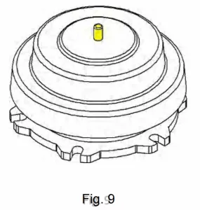
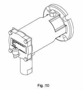
People often called an explosion-proof device (Fig 9).
The function of this device is to quickly release the gas pressure due to internal failure.
The APRD lid with a spring-loaded diaphragm installed will open at a predetermined pressure level of 10 PSI.
And it will be closed again when the pressure is restored.
FPRD has a yellow alarm button. It will stand out when the pressure is abnormal.
FPRD is equipped with SPDT alarm for the convenience of remote monitoring.
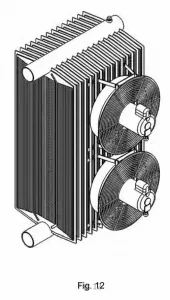
The forced air cooling fan (Fig 12) can be optionally used in a device equipped with a radiator.
It increases the KVA capacity of the pad-mounted transformer by 25% without overheating or adverse effects.
Daelim can increase or decrease the number of fans according to user needs.
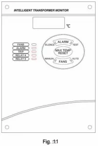
The fan can be controlled by a gauge oil thermometer with contacts or a winding temperature indicator.
Installing an electrical Pad Mounted transformer on-site can be challenging, much more so if this is your first time or you are unfamiliar with electrical Pad Mounted transformers.
To begin, the electrical transformer must be handled cautiously to avoid internal damage, which would result in inoperable power equipment.
It is critical to observe all safety procedures and to provide protective equipment to the construction worker who will be handling the transformer.
These suggestions apply to both dry-type and liquid-filled Pad Mounted transformer installations.
It is critical that you understand which acceptance tests must be performed.
All relevant acceptance tests should be conducted in accordance with ANSI/IEEE and NEMA standards.
An externally operated no-load tap changer (NLTC) (Fig 14 A and B) is suitable for all kinds of pad-mounted transformers.
The rated voltage of the tap under normal conditions is -5%~5%.
This means that the output voltage of the pad mount transformer is adjusted in increments of 2.5%.
The tap switch is designed as an operable handle.
It is available in two styles.
Each of which requires a slightly different method to change tap settings.
The four-position LBOR segment switch (Fig 16 A and B) is optionally provided in the loop feeder Pad-mounted transformer.
It can select the feed source.
It can turn on or off the feed through the loop.
The spring-loaded activation mechanism ensures rapid load disconnection.
Only hot rods can be used for switching.
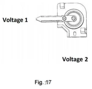
The Dual Voltage Switch (Fig. 17) can facilitate selecting one primary voltage from another.
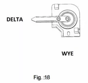
Due to the special needs of customers, the Delta-Wye switch can be installed on the Pad-mounted transformer (Fig 18).
It can help switch between Wye and Delta voltage.
Lightning arresters (Fig 16) are optionally installed in the base pad mount transformer.
If there is a voltage surge, Surge arresters can provide protection for the transformer.
Under normal circumstances, the arrester terminals will withstand line-to-ground voltage.
When a voltage surge occurs, the arrester will be grounded in order to keep the voltage normal.
The arrester will automatically recover after the surge ends.
Installing an electrical Pad Mounted transformer on-site can be challenging, much more so if this is your first time or you are unfamiliar with electrical Pad Mounted transformers.
To begin, the electrical transformer must be handled cautiously to avoid internal damage, which would result in inoperable power equipment.
It is critical to observe all safety procedures and to provide protective equipment to the construction worker who will be handling the transformer.
These suggestions apply to both dry-type and liquid-filled Pad Mounted transformer installations.
It is critical that you understand which acceptance tests must be performed.
All relevant acceptance tests should be conducted in accordance with ANSI/IEEE and NEMA standards.
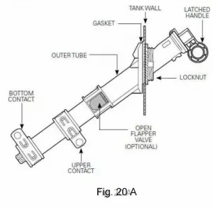

Bay-O-Net fuse replacement instruction (Fig. 20 B):
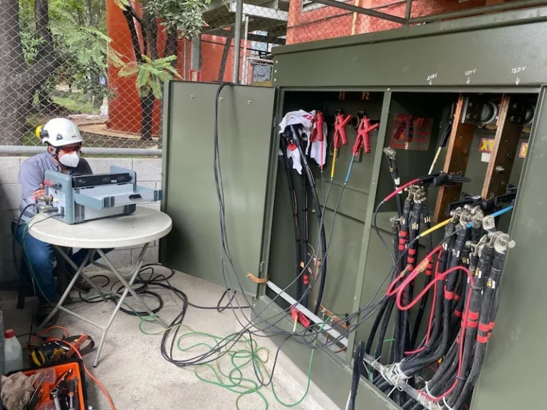
A common Padmount Transformer used in Bitcoin mining farms is a step-up transformer.
Mainly used for the conversion of input electric energy.
The stage from transportation to the site to installation and commissioning is particularly critical.
The installation process has a direct impact on the operation of the pad-mounted transformer.
In order to reduce the error rate, avoid unnecessary losses, and promote the stable operation of the power generation system, professionals are assigned to be responsible for installation and commissioning.
WARNING: Only professionals can operate the link of the Pad-mounted transformer.
Before the work starts, a full inspection of the pad-mounted transformer is required.
Confirm that all its accessories are normal. There was no damage.
The following are the inspection steps:
Confirm the liquid position of the oil tank.
Perform transformer turns ratio and DC insulation tests.
Ensure that the outer surface of the transformer is complete.
Check the condition of all seals and gaskets.
Pad mount transformer needs to be placed in an open place. This will facilitate a comprehensive inspection.
Outdoor Installations Pad-mounted Transformer
The correct placement of the transformer should be far away from the structure that restricts the airflow around the equipment.
Indoor Installations Pad-mounted Transformer
Special precautions should be taken.
The venue must be ventilated.
Confirm that the vent is open. This is to prevent accidental overheating of the transformer.
If good natural ventilation is not possible, a fan can be used to make the transformer out of the ventilated environment.
The pad-mounted transformer must be prevented from being on a level ground.
The ground must be concrete.
The location must prevent the transformer from tilting more than 2 degrees from the horizontal.
The pad-mounted transformer oil tank and the cabinet base provide provisions for installing splints to secure the transformer to the mat.
There must be no gap between the gasket and the cabinet.
Add permanent mortar to seal the gaps.
A comprehensive inspection of the pad-mounted transformer is required, including appearance, performance, etc., to ensure that it has no quality defects.
Due to the long transportation distance, the Padmount Transformer should be prevented from being damaged, and the fuel tank should be well sealed and there should be no oil leakage;
All parts are not lost, and the specifications meet the requirements;
Relevant documents and various signs are indispensable, and technical clarification should be done well.
It is necessary to consider the installation method and the required equipment, and formulate a reasonable and feasible construction plan according to the structural characteristics of the substation system. The installer should be familiar with the surrounding environment and understand the workload and process.
Test instruments, installation tools, cranes, cleaning materials and bonding materials must be prepared, and there is no quality problem, and the necessary basic conditions for installation work are provided.
The installation site is located in the substation, and the surrounding environment is cleaned up to control possible safety hazards to prevent accidents.
It is also necessary to pay attention to insulation inspection. If the insulation performance of the coil is damaged or there is insufficient strength in the insulating oil experiment, it should be dealt with in time before the next work can be carried out.
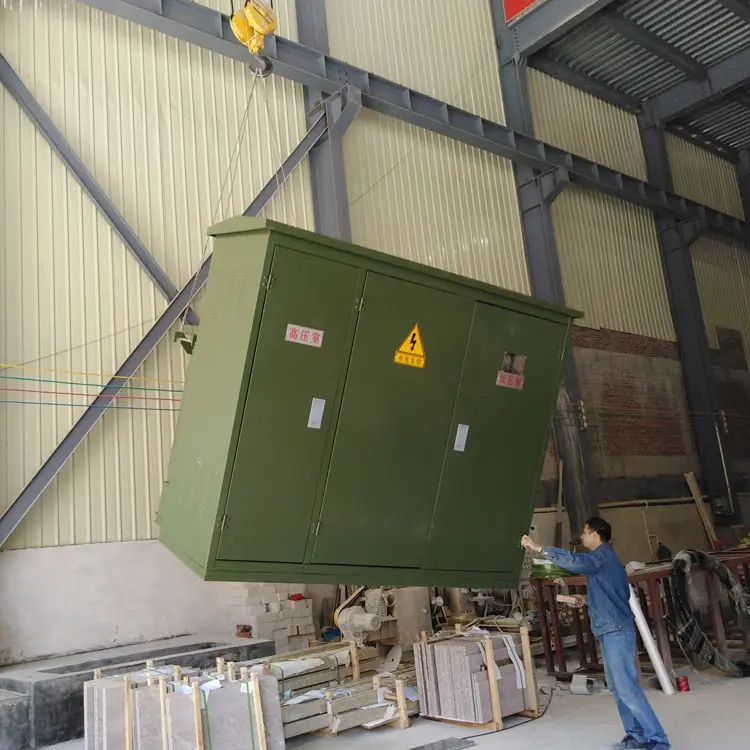
First determine the location of the pad-mounted transformer, and then unload the truck into the room. If the Bitcoin mining farm is not suitable for the use of lifting equipment, temporary rails need to be built.
After removing obstacles on the ground, set up a sleeper platform to be level with the indoor ground;
Then lift the Padmounted transformer on the paved track with the help of a lifting chain and a three-step ladder, and pull it into a predetermined position indoors.
The design drawings must be accurate, including the area occupied by the transformer, the length from the wall, etc., should be accurately calculated, and the deviation should not exceed 30 mm.
After being in place, the shock and vibration conditions received during transportation should be recorded, and the results should be analyzed whether it exceeds the allowable range.
The installation of the bench is also very important. It is fixed on the pole with 4 channel steel, the plane slope is controlled within 1%, and the height from the ground should be moderate.
The waistband is 0.5 m away from the live part. It must be firm and not loose. Use a 6 mm iron wire to tie it at least twice.
Taking safety into consideration, a dust cover should be installed on the head of the high-voltage column and a warning sign should be hung up to prevent anyone from touching it.
Installing an electrical Pad Mounted transformer on-site can be challenging, much more so if this is your first time or you are unfamiliar with electrical Pad Mounted transformers.
To begin, the electrical transformer must be handled cautiously to avoid internal damage, which would result in inoperable power equipment.
It is critical to observe all safety procedures and to provide protective equipment to the construction worker who will be handling the transformer.
These suggestions apply to both dry-type and liquid-filled Pad Mounted transformer installations.
It is critical that you understand which acceptance tests must be performed.
All relevant acceptance tests should be conducted in accordance with ANSI/IEEE and NEMA standards.
In the rainy summer weather, the power generation system is prone to lightning strikes. If the grounding resistance is too large, it is difficult to introduce the current carried by the lightning into the ground in time, causing the pad-mounted transformer to be burned out.
Therefore, when installing a grounding device, the grounding resistance must meet the requirements.
Afterwards, the grounding device must be tested, and the soil can not be filled until it is qualified.
In addition, in order to reduce the trouble during maintenance, the Padmounted transformer housing should also be well grounded and tightened with bolts. It is best not to use welding to fix it.
The horizontal grounding body and the vertical grounding body together form the underground part.
The former is a flat steel 5 m long with a buried depth of 0.5 m, and the latter is 3 angle steels 2 m long, which are driven directly on the basis of the horizontal grounding body. underground.
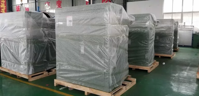
In order to maintain the nitrogen and oxygen content in the fuel tank, dry nitrogen in the fuel tank at 2 psi.
Confirm that the condensing heater is in a state where it can work normally.
The pad mount transformer must be placed in a dry and constant temperature place.
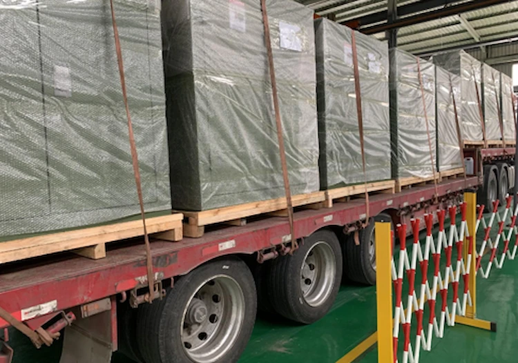
WARNING: The accessories of the transformer need to be kept carefully. Can not be used for other purposes.
CAUTION: Cranes and forklifts with a load capacity greater than the weight of the Pad-mounted transformer must be used.
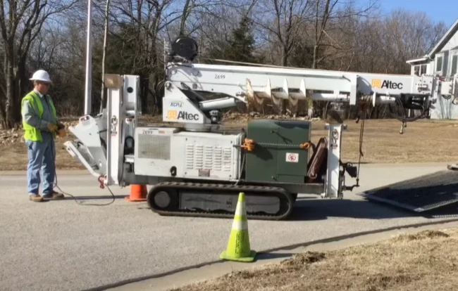
The wooden pallet holding the Pad-mounted transformer is recommended to be moved with a forklift.
When using a forklift, make sure that the fuel tank of the pad mount transformer is on the side close to the driving position. Place it overturned.
If you don’t have a forklift, you can use a crane to move it.
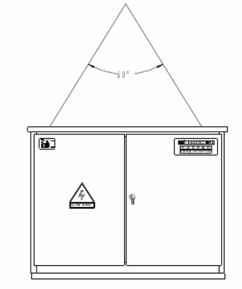
Before starting the lifting work, check whether all the equipment used for lifting can work normally.
There are lifting eyes on both sides of the fuel tank. If a wire rope is used, the lifting angle must not be greater than 60.
The Pad-mounted transformer must be in an upright state when being lifted.
If necessary, use cross bars to support the wire rope to avoid any deformation of the box structure or the lifting hook.
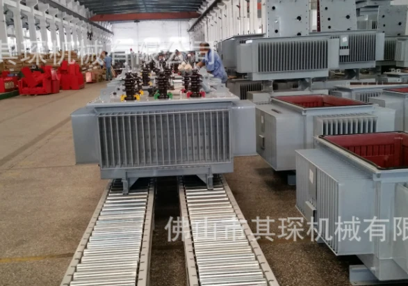
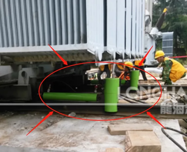
When the use of the crane is restricted, the pad-mounted transformer can be moved using a rolling device.
During the movement, the transformer should be kept in a vertical state and moved horizontally.
The rolling equipment must be able to provide a pulling force higher than the weight of the transformer.
The multi-roller design can help the pad mount transformer move more smoothly.
Routine inspections of the outside of the equipment should be carried out regularly.
Remove any dirt from the base and cabinet area to prevent premature rust and deterioration.
Check whether the surface paint of the pad-mounted transformer is complete.
If there is paint peeling on the surface, you can take a specific picture and tell Daelim.
Daelim staff will inform you of the type of paint used on specific parts.
This will help you improve the paint touch-up efficiency.
Regularly confirm whether each instrument is working properly.
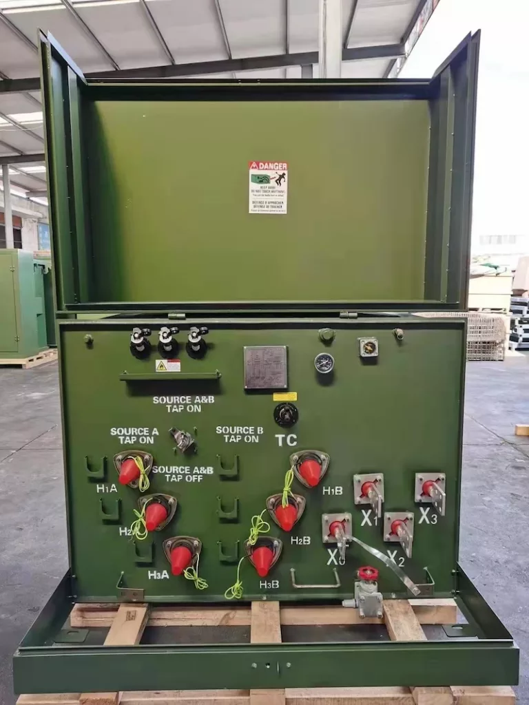
15 kva Single phase pad mount transformer
Dimension (W*D*H): 610*740*840mm;
Oil Weight: 45 kg;
Total Weight: 294 kg;
25 kva Single phase Padmounted transformer
Dimension (W*D*H): 610*740*840mm;
Oil Weight: 68 kg;
Total Weight: 362 kg;
37.5 kva Single phase pad-mounted transformer
Dimension (W*D*H): 610*760*840mm;
Oil Weight: 75 kg;
Total Weight: 476 kg;
50 kva Single phase pad-mounted transformer
Dimension (W*D*H): 610*810*840mm;
Oil Weight: 93 kg;
Total Weight: 553 kg;
75 kva Single phase Padmount Transformer
Dimension (W*D*H): 610*860*840mm;
Oil Weight: 132 kg;
Total Weight: 672 kg;
100 kva Single phase pad-mounted transformer
Dimension (W*D*H): 740*940*910mm;
Oil Weight: 141 kg;
Total Weight: 742 kg;
167 kva Single phase pad-mounted transformer
Dimension (W*D*H): 760*1190*910mm;
Oil Weight: 207 kg;
Total Weight: 952 kg;
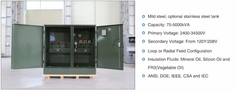
75 kva Three phase Padmounted transformer
Dimension (W*D*H): 1390*910*1430mm;
Oil Weight: 120 kg;
Total Weight: 645 kg;
112.5 kva Three phase Padmounted transformer
Dimension (W*D*H): 1420*920*1430mm;
Oil Weight: 138 kg;
Total Weight: 729 kg;
150 kva Three phase pad mounted transformer
Dimension (W*D*H): 1510*980*1530mm;
Oil Weight: 201 kg;
Total Weight: 989 kg;
225 kva Three phase pad mounted transformer
Dimension (W*D*H): 1600*1000*1660mm;
Oil Weight: 230 kg;
Total Weight: 1195 kg;
300 kva Three phase padmounted transformer
Dimension (W*D*H): 1660*1080*1680mm;
Oil Weight: 260 kg;
Total Weight: 1415 kg;
500 kva Three phase pad-mounted transformer
Dimension (W*D*H): 1810*1160*1790mm;
Oil Weight: 325 kg;
Total Weight: 1905 kg;
750 kva Three phase pad-mounted transformer
Dimension (W*D*H): 2030*1300*2030mm;
Oil Weight: 535 kg;
Total Weight: 2755 kg;
1000 kva Three phase pad-mounted transformer
Dimension (W*D*H): 1651*1549*1854mm;
Oil Weight: 650 kg;
Total Weight: 3235 kg;
1500 kva Three phase pad-mounted transformer
Dimension (W*D*H): 2210*1470*2150mm;
Oil Weight: 748 kg;
Total Weight: 5835 kg;
2000 kva Three phase pad-mounted transformer
Dimension (W*D*H): 2380*1600*2220mm;
Oil Weight: 950 kg;
Total Weight: 6430 kg;
2500 kva Three phase pad-mounted transformer
Dimension (W*D*H): 2480*1650*2330mm;
Oil Weight: 1020 kg;
Total Weight: 8865 kg;
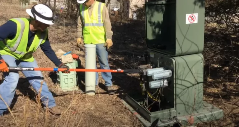
WARNING: Excessive current will damage the transformer windings. The tap changer and other switches must be located in the positions shown on the transformer nameplate.
WARNING: In the energized state, changing the dual voltage of the pad mounted transformer will cause an electric shock to the human body.
ELECTRIK SHOCK: The power must be disconnected before servicing or operating the arrester. Otherwise, it will cause serious injury, death or equipment damage.
CAUTION: The impulse test of the transformer should avoid the arrester. Otherwise, the arrester will be damaged.
WARNING: Disconnect the power before operating Switching. Otherwise it will cause serious casualties.
WARNING: Do not install fuses to complete the circuit. It will cause the pad-mounted transformer circuit to fuse after re-energization. Caused serious casualties.
WARNING: Removing the fuse when there is still voltage inside the fuel tank will result in personal injury or death.
With the expansion of market demand, more and more Padmounted transformer manufacturers appear on the market.
But how to choose a suitable pad-mounted transformer manufacturer?
Below, we consider it in Four directions.
First confirm what type of pad-mounted transformer you need to buy?
Is it a three-phase pad mount transformer?
Or is it a single-phase pad mount transformer?
Confirm the Rated Power (KVA) of the pad-mounted transformer that you need to purchase.
Daelim has an excellent team of designers.
Whether it is a three-phase transformer or a single-phase transformer.
Daelim has more than 15 years of design and production experience.
Daelim can design and produce a pad-mounted transformer suitable for you according to your needs.
There are many traders pretending to be factories.
So how do you recognize whether the counterparty is a trader or a factory?
You can ask the other party to provide a business license.
And through the business license to check whether the other party has a factory.
Because the regulations of the power system of each country are different.
It is necessary to confirm whether the other party’s production has international certification.
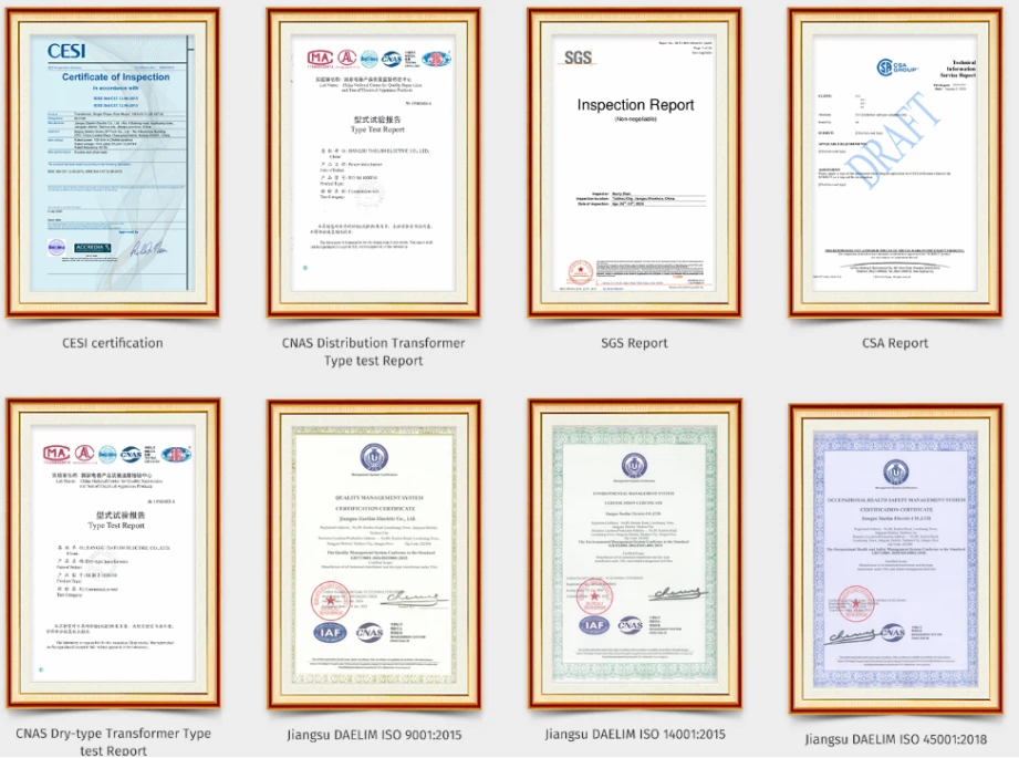
Common certifications for transformers are: SGS, CNAS, CE, SA, CESI.
Daelim as a good pad-mounted manufacturer has all the above certifications.
The following are the certification and patent certificates obtained by Daelim.
Whether a Padmount Transformer manufacturer has export experience is extremely important for your purchase.
It represents whether you can purchase a pad-mounted tranformer that meets the requirements of the local market.
It represents whether your purchase can proceed smoothly.
It represents whether your follow-up service can be complete and orderly.
Daelim has 15 years of experience in the production and export of tranformers.
Daelim’s products are exported to more than 30 countries and regions.
And can provide the completed installation and commissioning and other sales back-end services.
Below is a photo of Daelim and their business partners.

Due to the impact of the epidemic, you cannot go to the factory for on-site inspections.
But you can view it through video and other methods.
You need to know whether this Padmounted transformer manufacturer has complete experimental equipment.
Does the pad-mounted transformer have a large workshop?
Does the transformer have a strong R&D team?
Daelim has complete production and testing equipment.
It includes a transformer Drying oven, a test console, Lighting impulse equipment, epoxy vacuum pouring machines, silicon steel sheet shearing automatic line…
Below are photos of these devices.
During routine operation, pad mounted transformers create overvoltages separately in electro-magnetic short-term events. It is necessary for transformers to assess the system's overvoltage levels in the layout and production phases, and suggest approaches to limit them. No pad-mounted transformer can be considered totally safe.
As a result, it is necessary to systematize manufacturing during the advancement and manufacturing of pad mounted transformer.
And in the process of installing the transformer, the building was performed in rigorous accordance with the setup specs.
Next, we will information the typical problems and solutions for pad-mounted transformers.
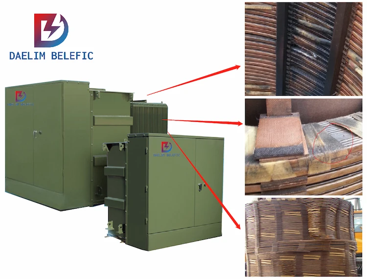
The transformer's malfunction is an outcome of a short circuit between its turns.
Upon exam of the crash pad place transformer, it is observed that the incorporated merges of stage A and C have actually been harmed, with noticeable indicators of shedding on the high-voltage clamp situated over the fuse point of the phase C winding defense fuse.
The occurrence continues to escalate even after the fuse has actually blown, showing that the mistake arc has not been effectively extinguished.
In the mishap, the welding joint of the top cover of this transformer was torn entirely, and the arc light and hot oil sprayed out from the cracks. This type of crash can totally threaten the safety of the surrounding workers.
The pad installed transforme utilizes a collection of integrated current-limiting fuses immersed in the transformer oil as backup security when the transformer has an internal fault such as a short circuit in between turns.
Usually, in circuit layout, a group of seclusion switches is placed on the high-voltage input side of the pad-mounted transformer, and the concern of short-circuit protection is no longer an issue.
It can be challenging to identify the specific place of a fault in a transformer that has a conventional box structure. This difficulty develops when the built-in fuse, which is immersed in the oil of the Padmounted transformer, is not able to successfully isolate the mistake as a result of extreme oil degradation and insulation product failure.
The pad-mounted transformer ignited since the building and construction website's power supply was strained, requiring the installation of a brand-new pad-mounted transformer.
Complying with basic fixing procedures, the power supply company have to halt power distribution to the building website and, after reassessing the site's electricity ability, cover the expenditures for a brand-new transformer substitute prior to recovering power.
With the accelerated economic growth of prefectures and cities, the power tons of business in numerous industrial parks continues to increase, and the ability of pad mounted transformers in city locations commonly gets to full-load operation. The transformer is in the overload procedure state.
Especially throughout the peak load period in winter, the surface area temperature level of the transformer is as high as 70 degrees Celsius, and the swirl present temperature level created by the iron core is as high as 200 degrees Celsius.
To lower the temperature level of the high pad mounted transformer, the power supply business needed to decrease the amount of electricity being utilized by the area building and construction website.
At the same time, the substation puts followers in to cool the Padmount Transformers. The fans run 24 hours a day, and the day-to-day power consumption is very high.
The too much lots on the pad-mounted transformer is substantially impeding the progress of community advancement.
Nowadays, the power problem hinders the fast advancement of the country and the area to a particular level, and the energy consumption in all areas is very large, so the environment-friendly energy source is progressively becoming the emphasis of individuals's focus. Currently, the pad-mounted transformer used on wind generators has numerous benefits, but there are still numerous issues that need to be solved. For that reason, at this stage, it is of practical importance to reinforce the study on the application of pad mounted transformer in wind power generation.
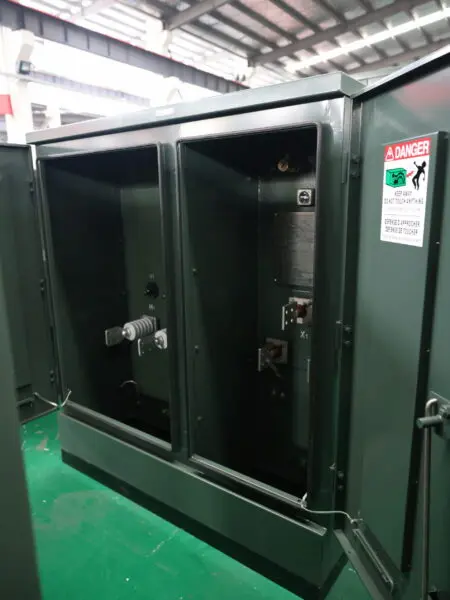
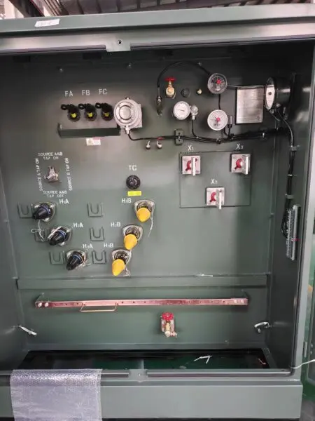
A wind power task, installed capacity of 40 MW, longitude 109 ° 26 ′ ~ 110 ° 39 ′, latitude 38 ° 51 ′ ~ 39 ° 01 ′, elevation between 1 000 ~ 1 300 m. The site area is bordered by S204, S301 rural freeway via, and there are country roadways attached, the installment of outside transport is fairly convenient. The site location is surrounded by S204 and S301 provincial freeways and linked by rural roads, with convenient external transportation, and 12 collections of 3.3 MW wind generators are installed, with a mounted capability of 39.6 MW. The rated voltage of the outlet of each wind generator of wind power generation is 690 kV, and each wind turbine is equipped with a box-type substation, which adopts the kind of one equipment and one transformer, and attaches to the job’s recently created 110 kV improving voltage line via 2 sets of 35 kV collection agency lines. It is attached to the freshly constructed 110 kV booster station by 2 35 kV collector lines, and then linked to the completed 110 kV switching station in the northwest direction by one 110 kV line.
Wind power is a tidy, non-polluting, and renewable energy resource that shows terrific possible for advancement. The output power of a wind turbine usually runs at 690 V. To make sure the reliable transmission of this power over a prolonged period, the use of a pad-mounted transformer in the training system is common method. An evaluation and thorough conversation of the pad-mounted transformer are performed thinking about variables such as size, weight, wire setup, operational needs, upkeep, and upgrading. By comparing three generally made use of wind power pad-mounted transformer setups in terms of application range and construction rate, their strengths and weaknesses are evaluated.
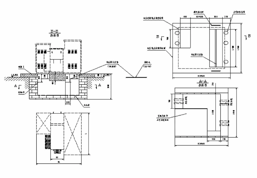
The almost all of the pad-mounted transformer foundation is above the initial ground and is an enhanced concrete structure. This kind of pad mounted transformer base is characterized by its stunning appearance and convenience of changing and upkeep of the pad-mounted transformer base. However, this type of pad mounted transformer base is extremely susceptible to rainfall during the rainy season due to its large interment deepness and small subjected surface area on the top surface area of the base, which requires it to be pumped at regular periods, thus creating a large amount of hinderance to its typical procedure. During the construction period, the quantity of planet to be excavated is relatively large, and if in the area of inadequate dirt, it is also necessary to execute sloping, as a result of the limited building and construction space, consequently, in the building development, the cycle is long.
This project suggests using an upreared steel platform to improve the standard structure of a wind power pad-mounted transformer. This prefabricated system is made to surpass the typical framework and can streamline the construction procedure, lowering effort and time required for setup.
From the outcomes of method, this devices has the advantages of easy structure, conserving raw materials, convenient construction, etc, can be a great option to the fact of the premade pile penetration level is challenging to control, is a sort of wind power generation pad-mounted transformer for electric and building and construction design. traditional steel system pad mounted transformer base belongs to An average pad-mounted transformer foundation includes 2 components, namely: steel platform and strengthened concrete precast heaps, making use of steel beam of lights bonded to the leading plate of strengthened concrete precast heaps to complete the building of pad mounted transformer structure. Nevertheless, in the real use the procedure, for the site distributed, complex geological problems of the regional decentralized wind power jobs, this upreared steel platform tool for wind power pad-mounted transformer foundation successfully resolves the issues because of the difficult building process, built piles infiltration is challenging to manage, wintertime construction difficulties, etc, the general building cycle is much shorter, the building and construction top quality of the construction procedure is ensured, the construction job will certainly be steady and smooth. The general construction period is much shorter, and the construction quality is assured throughout the building process, and the building and construction work will be performed stably and smoothly.
To expedite the building of the pad-mounted transformer foundation, enhance the building process, and decrease issues such as spread machinery areas and tough geological conditions, we have created a device that satisfies site demands while focusing on cost-effectiveness and functionality. This tool functions as an important reference point for future building and construction undertakings in this area. To ensure the gadget’s functionality and guarantee its safety and longevity, it has been segmented right into three major components: steel system, steel pier, and steel mat.
The steel system is made up of a steel frame and a system plate. The steel structure is constructed with I-beams, particularly HM194 × 150 × 6 × 9 mm, which describes a height of 194 mm, width of 150 mm, web plate density of 6 mm, and flange plate thickness of 9 mm. The product made use of for the steel frame is Q235B steel. The platform plate is made of non-slip steel plate, readily available in three sizes: 3496 mm × 750 mm × 9 mm, 4850 mm × 750 mm × 9 mm, and 4850 mm × 750 mm × 9 mm. The steel pier sustaining the platform plate is 10 mm thick and constructed from Q235B steel. The pier has a size of 1300 mm and a size of 200 mm, with 6 teams of piers in total amount. The top plate of the steel pier and the steel platform are bonded together utilizing E43 type collection welding rod, with a weld height of at least 10 mm and full welding protection. In addition, a steel mat made of 20 mm thick Q235B steel is used, gauging 3000 mm long, 800 mm vast, and 20 mm thick, with 3 groups in total amount.
The wind generator structure is used as the structure of the household pad place transformer and the service provider of the household pad install transformer, to ensure that the service provider has great security. At the end of the building and construction of the wind generator foundation and the RESIDENTIAL PAD MOUNT TRANSFORMER structure utilizing concrete unscathed, it was covered with backfill and placed in the ground. Due to the fact that the foundation of the wind generator and the structure of the RESIDENTIAL PAD MOUNT TRANSFORMER are built and shaped at one time, it conserves land, lowers the work of civil engineering, and accelerates the building procedure. The structure of this wind power box transformer has a steady framework, which can decrease the amount of work and speed up the building procedure.
In recap, the assistance of RESIDENTIAL PAD MOUNT TRANSFORMER is vital in energy transmission, and its capacity to run smoothly is closely pertaining to energy transmission. In the future power system, the position of box transformer will certainly be a lot more famous, and the issues it deals with will certainly be more complicated. For that reason, in this instance, the staff of wind ranches need to remain to discover the type of box transformer structure made use of in wind ranches, and advanced a much more scientific use the strategy, so regarding better ensure the financial benefits of wind ranches, and to promote the benign growth of the whole culture and economy.
A 3-phase pad-mounted transformer is an essential outdoor electrical transformer that provides a safe and efficient method for stepping down high-voltage electricity from the power grid to a lower voltage suitable for commercial, industrial, and residential use. Unlike pole-mounted transformers, it is installed on the ground and enclosed within a secure housing, making it ideal for underground power distribution and areas where aesthetic considerations are important. This type of transformer is particularly valued in utility-grade and industrial power supply applications, where reliable voltage regulation and load balancing are critical for maintaining a stable distribution network.
The 3-phase pad-mounted transformer has several important specifications that determine its suitability for various applications. It typically operates within medium voltage ranges, such as 15 kV to 35 kV on the primary side, with secondary voltage outputs tailored to local requirements. Its design allows it to handle higher loads compared to single-phase transformers, making it ideal for power distribution in commercial complexes and industrial settings. Additionally, transformer cooling systems, either oil-immersed or dry-type, ensure effective heat dissipation for maintaining optimal performance under varying load conditions.
This transformer type offers numerous benefits, including improved safety and aesthetic integration into urban environments. Its enclosed design reduces the risk of electrical exposure, making it safer for installation in public spaces. The 3-phase pad-mounted transformer also supports efficient load balancing, ensuring that power delivery remains stable even during peak usage periods. Furthermore, its robust design makes it suitable for outdoor conditions, reducing the need for frequent maintenance and offering a long service life, which is essential for utility-grade installations.
A 3-phase pad-mounted transformer is widely used in various applications, such as powering commercial buildings, supporting industrial power supply needs, and serving as a substation transformer for smaller distribution networks. Its ability to integrate seamlessly with underground power distribution systems makes it ideal for urban and suburban developments where overhead lines are impractical. By stepping down the voltage at the point of use, it ensures efficient power delivery and minimizes energy losses in the distribution network.
Proper installation is crucial for the performance and safety of a 3-phase pad-mounted transformer. It must be placed on a stable pad with adequate space for ventilation and access to primary and secondary voltage connections. Regular maintenance, including inspections of insulation, cooling systems, and electrical connections, ensures the transformer operates efficiently and extends its service life. A well-maintained transformer supports high-efficiency power distribution, making it a reliable choice for modern electrical power equipment needs.
By understanding the capabilities and applications of 3-phase pad-mounted transformers, utilities and businesses can make informed decisions about integrating these critical components into their power distribution systems, ensuring efficient and reliable energy delivery.
After filling in the contact information, you can download the PDF.